Sharif University of Technology
Scientia IranicaTransactions C: Chemistry and Chemical Engineering http://scientiairanica.sharif.edu
Electrochemical energy conversion realized through
Ag@Pt/rGO nano-catalyst enhancing activity of the
ORR process in a PEMFC
A. Esfandiari and M. Kazemeini
Department of Chemical and Petroleum Engineering, Sharif University of Technology, Tehran, P.O. Box 1136594655, Iran. Received 14 August 2018; received in revised form 7 August 2019; accepted 16 September 2019
KEYWORDS Core-shell; Electrocatalyst; Oxygen reduction; PEMFC;
Reduced graphene oxide.
Abstract. In this study, core-shell structures of Ag@Pt nanoparticles (NPs) were dis-persed upon reduced Graphene Oxide (rGO) support that contains dierent Ag:Pt mass ra-tios synthesized through the ultrasonic treatment method. These were applied to an Oxygen Reduction Reaction (ORR) process in a Proton Exchange Membrane Fuel Cell (PEMFC). The morphology of as-prepared catalysts was characterized through High-Resolution Transmission Electron Microscopy (HRTEM), X-Ray Diraction (XRD), and Induced Coupled Plasma Atomic Emission Spectroscopy (ICP-AES) analyses. The ORR activities and stabilities of catalysts were studied through electrochemical measurements of Cyclic Voltammetry (CV) and single cell tests, respectively. Results revealed that the prepared Ag@Pt/rGO catalysts possessed a core-shell nanostructure, and the one with an Ag:Pt mass ratio of 1:3 displayed the largest electrochemical surface area of 77.6 m2 g 1. Moreover,
this material provided the highest stability among other synthesized electrodes, containing dierent Ag:Pt mass ratios, and the obtained commercial Pt/C electrode. The maximum power density for the MEA prepared with this electrocatalyst was determined to be 55% higher than that of the commercial Pt/C, evaluated through single cell techniques. Thus, the understudied material seems to be a very promising cathode for use in PEM fuel cells. © 2019 Sharif University of Technology. All rights reserved.
1. Introduction
In order to obtain a clean and environmentally-friendly power source, PEMFCs are considered to more mature and developed than other green devices due to their possessing advantages: i) a low working temperature of 80C, ii) good energy eciency, iii) high power density
per unit volume, iv) immobilized electrolyte, and v) near-zero emission [1-5]. In light of growing demand for the commercialization of PEM fuel cells, consider-able attention has been given to cost reduction while
*. Corresponding author.
E-mail address: [email protected] (M. Kazemeini) doi: 10.24200/sci.2019.51600.2270
increasing the durability of such systems [5]. Platinum supported on electrically conductive carbon is the most widespread electrocatalyst used in such devices. Nev-ertheless, to reach sucient current densities, particu-larly for sluggish reaction kinetics of Oxygen Reduction Reaction (ORR) on the cathode side, high loadings of Pt were utilized to reach appropriate levels of performance [6-9]. Meanwhile, Pt's high cost has led to many eorts for using it more eectively, e.g., alloying platinum with transition metals [10-14] or employing its synergetic chemical coupling with co-catalysts or support [15]. Nonetheless, the catalytic activities and long-term stabilities of these materials used for the ORR taking place through the PEM fuel cells are still insucient [16,17]. On the other hand, core-shell nanoparticles are considered to be innovative
struc-tures, in which the Pt species (i.e., as the shell part) represents a more ecient material (compared to that of the core one) for the PEM fuel cells. Such electrode structures provide remarkable properties when utilized in the aforementioned fuel cells. These properties in-clude: i) enhanced catalytic activities attributed to the ligand performances, leading to changes in the d-band position and, hence, improving the charge transfer, ii) providing higher activation energies, iii) possessing better adsorption behaviors in particular for the oxygen reduction reaction, and iv) consuming lower amounts of the Pt, leading to the overall cost reduction [18-28]. It is noteworthy to mention that, in such oxygen reduction reactions, the catalysis occurred as a surface phenomenon [29]. Furthermore, the Pt might have interacted electronically with the metal core, increasing the activity and durability of this material for the ORR. This would have taken place through the reduction of the Pt-Pt bond distance at the interface and near-interface layers of the core, as well as the Pt shell. This is attributed to the enhancement of the Pt's 3d-orbital vacancies [30,31]. In this venue, therefore, many research pieces are involved with the preparation of the core-shell structured catalysts, some of which include Co@Pt structure prepared by the reduction method and the subsequent electroless deposition [32], Ru@Pt structure [33], and Pd@Pt electrocatalysts prepared by the replacement and electroless deposition [34].
On the other hand, durability of synthesized electrocatalyst is considered to be one of the principal factors in deciding upon an appropriate metal, playing the role of the core in this structure. Therefore, based upon possessing a similar crystal structure and a lattice parameter as the Pt species, silver was decided to be a promising metal for platinum core-shell structure. In other words, Ag is selected since it is a transition metal that possesses face-centered cubic (fcc) crystals and has lattice spacing being a little bit larger than that of the platinum [35]. Furthermore, these similarities in the lattice spacing facilitate the growth of Pt (shell) upon Ag (core) [36,37]. In the past few years, Ag@Pt core-shell structures have been investigated in PEMFCs [38-40]. Yu et al. [38] applied Ag@Pt core-shell structure with dierent Ag:Pt mass ratios and a total metal loading of 40% supported on multi-wall carbon nan-otubes (MWCNT). Their results demonstrated that the ECSA of Ag@Pt at the optimum mass ratio was 70.63 m2g 1. Then, their group upgraded the
carbon-based MWCNT by adding MnO2 to Ag@Pt/MWCNT
electrocatalysts such that their ndings ended up in an optimum activity with an electrochemical area of 85.83 m2 g 1. This material possessed a composition
of Ag10%@Pt10%/MWCNTs-a-MnO2 20% and was
applied to the ORR [38]. In another research, Koh et al. [40] applied dilute aqueous solution of PtCl4 (0.1
g L 1) blended with a commercial Ag nanocatalyst
with no extra chemical agents added and set the mass ratio of Pt:Ag to about 1:19 in order to create a thin monolayer of Pt-shell over the silver nanoparticles followed by sonication. Their results demonstrated a good progress in the durability and activity of the electrocatalyst [40].
In addition, one way to enhance the electrochem-ical (active) surface area (ECSA) per unit mass of an electrode often involves reducing the size of particles [9] and constructing core-shell or hollow structures [10-12]. Other routes include modifying the surface electronic states of the catalysts to tune materials' catalytic properties and seek enhancement in both activity and durability. Examples of these include alloying with another metal [13,14].
Ultimately, in order to boost the performance and promote the utilization of the Pt in a core-shell catalyst, support materials with particular capabilities were decided to be investigated. These abilities include: i) enhancing availability of the catalyst surface area for electron transfer, ii) providing preferable mass transport to the catalyst, iii) promoting transfer of electrons to the current collector, and ultimately iv) possessing a suitable capability for the water transport property of a core-shell structure towards the cathode side of a PEM fuel cell [41-43]. On the other hand, carbon black is commonly used as a carbon type support for the fuel cell electrocatalysts. Nonetheless, it faced corrosion when coupled in a core-shell structure with Pt as the dissolution-aggregation problems were observed by other researchers [44,45]. To resolve this issue, carbon nanotubes [46,47], mesoporous car-bon [48], carcar-bon nanobers [49], and graphene [50,51] were suggested to replace the carbon black. Moreover, in recent years, graphene has been recognized as a possible catalyst support due to its high electronic and thermal conductivity, stable physical and mechanical properties, and larger surface area compared with other sp2 bonded carbon materials [52,53]. In particular, Graphene Oxide (GO) consists of sheet-like graphene frameworks with carbonyl (C=O), hydroxyl (-OH), carboxyl (-COOH), and phenol groups. However, through a chemical or physical reduction of GO, it is transformed into a graphene-like semi-metal [54]. This made it a rather attractive support for the Pt core-shell catalyst utilized in a PEM fuel cell.
To the best of these authors' knowledge, to date, no such studies that demonstrate the graphene support for Ag@Pt core-shell structure applied to PEM fuel cells exist. In this venue, the current research reported a novel nano-catalyst structure, a silver-platinum core-shell supported upon rGO, to improve the durability, electrical conductivity, and activity of catalyst for the ORR in a PEMFC. For this purpose, a specic Pt:Ag mass ratio was supported upon the rGO by a reducing agent and the ultrasonic treatment
method. As the silver nanoparticles were loaded onto the graphene oxide surface, the GO substrate reduced while simultaneously Ag nanoparticles grew upon it. Then, Pt nanoparticles loaded upon the surface of the rGO already support the silver species. The congu-ration of the core-shell structure was veried through the HRTEM, XRD, and electrochemical techniques. Moreover, the best performing material in terms of the Pt:Ag mass ratio was determined. This catalyst system was investigated from both the activity and stability points of view for an ORR medium taking place in a PEMFC while its performance was compared with that of a commercial Pt/C material.
2. Experimental
2.1. Materials synthesis 2.1.1. Chemicals and reagents
Graphite akes were provided by the Sigma Aldrich Co. while concentrated sulfuric acid (H2SO4, 95%),
potassium permanganate, hydrochloric acid (HCl), hy-drogen peroxide aqueous solution (H2O2, 30%), HNO3,
AgNO3, sodium citrate, NaBH4, H2PtCl6.6H2O,
NaOH, and 2-propanol were all obtained from the Merck Chemical Inc. (Darmstadt, Germany). These chemicals were utilized without further purication. Naon® 115 membranes from Dupont® were
pre-treated with hydrogen peroxide, distilled water, and dilute H2SO4. In all preparation procedures and
analyses, deionized (DI) water through a Millipore system (Milli-Q®) was consumed.
2.1.2. Preparation of GO
Graphene Oxide (GO) used in this study was synthe-sized through Hummers and Oeman's method [55] in the following manner. Initially, 2 g of graphite akes and 2 g of NaNO3 were mixed in 50 mL of H2SO4
(98%) in a 1,000 mL volumetric ask. The mixture was kept in ice bath under continuous stirring in the range of 0 to 5C for 2 h. Then, 6 g of potassium
permanganate was added to this mixture very slowly. The addition rate was adjusted to keep the reaction temperature lower than 20C. Next, the mixture was
stirred at 35C until it became brownish. Then, it
was kept under stirring overnight at room temperature. This was followed by the slow addition of 100 mL of DI water under vigorous stirring at 98C, leading to
a change in color to brown. Then, the solution was diluted by adding additional 200 ml of DI water under stirring. Finally, the above resulting mixture treated with 10 mL of H2O2 to end the reaction was shown
through the appearance of yellow color. Next, for purication, the mixture was washed through rinsing and centrifugation rst with 10% HCl and, then, with DI water several times. Afterwards, ltrations and
dryings took place under vacuum, and Graphene Oxide (GO) was ultimately generated.
2.1.3. Preparation of rGO supported Ag nanoparticles The reduced GO supported Ag nanoparticles were prepared through a colloidal method by NaBH4 as a
reducing agent. Analogous to the procedure of Yu et al. [38], the graphene oxide powder was functionalized by introducing surface oxide groups onto it. In a typical one, Ag@Pt/rGO with a nominal Ag:Pt mass ratio of 1:1 (i.e., the quantity of metal accounts for 10% of the total mass of the electrocatalyst) was prepared. The graphene oxide powder was added to a mixture of 370 mL of 1 mM aqueous solution of AgNO3 and
1.6 mL of 38.8 mM aqueous sodium citrate solution (which acted as a stabilizer) under continuous stirring. Then, 37 mL of 22.4 mM aqueous NaBH4 solution
was added dropwise under rigorous stirring to the ask containing graphene oxide material until yellow Ag hydrosol was formed. As mentioned earlier, GO was reduced to rGO, while Ag nanoparticles were grown simultaneously upon it [56]. Next, the mixture was stirred overnight at room temperature to break down the residual NaBH4[38]. Due to the presence of oxygen
groups on graphene oxide, its surface became active and capable of absorbing Ag+. Therefore, the
core-shell structure formation of the Ag@Pt electrocatalyst was achieved more eortlessly.
2.1.4. Preparation of Ag@Pt/rGO electrocatalyst Ag@Pt electrocatalyst was supported on the synthe-sized rGO via the ultrasonic method through the following steps. Initially, reduced GO supported Ag nanoparticles were added to DI water and 2-propanol in an ultrasonic bath for 60 min. Then, a 0.03 M solution of H2PtCl6.6H2O was dispersed in this suspension
at dierent mass ratios of Ag:Pt to obtain a total metal loading of 10 wt% under constant stirring and ultrasonic conditions. This was performed for an hour while a few drops of a 1.0 M NaOH solution were used for adjusting the pH at around 10. Finally, the electrocatalyst was ltered and washed with DI water and acetone several times. This material was dried overnight at 80C.
2.2. Physical characterization
Powder X-Ray Diraction measurements (XRD) were performed using an X'Pert MPD Phillips diractome-ter with a Co X-ray radiation source and Ni ldiractome-ter in a continuous mode at 40 kV and 30 mA. The XRD patterns were obtained with a scanning rate of 1C min 1 and a step size at the 2 scan of 0.02 in
the range of 10-100.
To evaluate the bulk Pt and Ag contents of the synthesized electrocatalysts, Inductively Coupled Plasma (ICP-OES, Varian Vista-PRO, Australia) anal-ysis of the dissolved materials was carried out. In this
venue, 5 mg of each synthesized material initially was dissolved in a mixture of HCl and HNO3at a 3:1 mass
ratio and, then, reuxed at 120C for 8 h. Next, the
Pt and Ag atomic ratios were determined through the ICP technique using respective standard solutions with an error of around 2-4%.
The morphologies of Ag@Pt/rGO electrocatalyst were further investigated via High-Resolution Trans-mission Electron Microscopy (HRTEM) using a Philips Model CM200. Samples for these evaluations were prepared by dispersing 1.e 3 g of nanoparticles in
30.0 mL of ethanol using a sonication bath. Then, a few drops of it were placed upon a copper grid. Finally, this grid was dried at 80C for 12 h under vacuum to
get it ready for the HRTEM observations. 2.3. Electrochemical characterization
Cyclic Voltammetry (CVs) measurements required for determining the electrocatalytic activity of the Ag@Pt/rGO material with dierent mass ratios (of the Ag to Pt) were performed with an EG&G Princeton Applied Research Model 273A instrument. All elec-trochemical experiments were carried out in a well-established three-electrode cell assembled with: i) the catalyst-ink coated Glassy Carbon (GC) disk (of 0.0314 cm2area) as the working electrode, ii) platinum
wire (of 1.0 cm2area) as the counter electrode, and iii)
Ag/AgCl as the reference electrode. As the rst step in electrode drawing up, the glassy carbon electrode was polished with 0.1 m diamond solution until obtaining a mirror nish. The surfaces of all electrodes were cleaned by potential cycling in N2 and purged for 30 min while immersed in de-aerated 0.5 M H2SO4
electrolyte solution. Next, a 5 mg sample of the Ag@Pt/rGO electrocatalyst was added to a 3 ml mix-ture of 2-propanol and DI water. Then, it was placed in a sonication bath medium for 20 min. Next, 8 L of this catalyst suspension was transferred dropwise onto a GC substrate with 0.1 gPt cm 2-loading and was dried at
room temperature overnight. Then, 3 L of 0.05wt.% Naon®solution was introduced onto the Ag@Pt/rGO
electrocatalyst layer as an ionomer solution. Cyclic voltammograms were procured in 0.5 M H2SO4 with a
scan rate of 50 mV/s under N2atmosphere at 25C. In
order to rest assured about the quality and durability of the synthesized materials, Accelerated Durability Tests (ADT) were performed. This occurred by applying CV between 0:25 and 1.2 V versus the Ag/AgCl reference electrode at a scan rate of 50 mV s 1 for a particular
number of cycles. This simulated the environment of the membrane interface on the cathode side.
Next, Linear Sweep Voltammograms (LSV) and Electrochemical Impedance Spectroscopy measurement (EIS) were acquired. These were performed through the electrochemical cell, connected to a potentiostat-galvanostat (EG&G Model 273A) for the I-V
polar-ization measurements and to a frequency response de-tector (Model 1025) for the electrochemical impedance spectroscopy. LSV was performed at a scan rate of 5 mV s 1 in the potential range of 1 to -0.2V
versus the Ag/AgCl reference electrode being cathodic to the equilibrium potential of the oxygen electrode for the ORR measurements. To obtain charge trans-fer resistance (Rct), the electrochemical impedance spectroscopy measurement was developed at 0.5 V as opposed to the Ag/AgCl potential. The AC potential amplitude was 5 mV, while the frequency range was set at 10 kHz-0.01 Hz.
2.4. Fuel cell tests
PEM fuel cell performance tests were carried out in a single fuel cell. Membrane Electrode Assembly (MEA) was prepared initially by the spraying method. The prepared catalyst ink contained 2-propanol and distilled water (1:1 volume ratio) and a 15 wt% Naon solution (made of the 5% Aldrich's stock solution). Then, the mixture was treated for 20 min under ultrasonication to achieve a uniform dispersion. The resulting material was sprayed directly onto the Gas Diusion Layer (GDL) according to the following pro-cedure. First, the GDL was prepared from a suspension consisting of 30 wt% PTFE (which was prepared from a 6% solution by weight) and 70 wt% carbon Vulcan. Hence, the loading in the carbon and PTFE composite was 1 mg cm 2. Next, proper amounts of the PTFE
and Vulcan were added to the medium of isopropyl alcohol (IPA) - distilled water solution (in a 2:1 volume ratio) - and sonicated for 30 min. The suspension was painted onto a porous carbon paper and, then, dried at 80C for 30 min. The electrodes were heated at 280C
for 30 min to remove the dispersing agent (from the PTFE) and, then, were sintered at 330C for 30 min.
The DuPont's Naon-115 was utilized as a proton electrolyte membrane. It was boiled up in a 5 vol% H2O2solution for 1.5 h followed by rinsing and washing
in DI water. The resulting material was further boiled in 0.5 M H2SO4 for 1.5 h followed by washing with
several portions of DI water. The synthesized catalyst was mixed into the Naon solution and a solution of IPA: water (of 2:1 volume ratio) while it was sonicated for 30 min at room temperature in order to create a uniform reaction layer. The mixture was spread onto the Naon-115 membrane and sintered in a furnace at 350C for 30 min. Ultimately, the MEA was
assembled with the GDL for the electrochemical tests in a 6.25 cm2 Paxi-tech single fuel cell [57]. Accordingly,
both anode and cathode contained platinum loadings of 0.5 mg cm 2 (MEA-1) and a 1:3 mass ratio of
Ag@Pt/rGO (MEA-2) all with a Naon loading of 0.9 mg cm 2.
The electrochemical performance of the MEAs was determined by obtaining polarization curves. The
current voltage characteristics of dierent MEAs were acquired with feeding H2 and O2 onto the anode and
cathode electrodes, respectively. Measurements were performed at 80C and 1.5 bar with 90% Relative
Humidity (RH).
3. Results and discussion 3.1. Physical measurements
The composition of the synthesized catalysts and the actual Pt and Ag loadings were determined through the ICP-OES of Ag@Pt supported on rGO nanocomposite, as tabulated in Table 1. These results indicated that the actual and nominal atomic ratios of Ag and Pt in the synthesized electrocatalysts were of the same order. This means that Pt and Ag were completely deposited upon rGO.
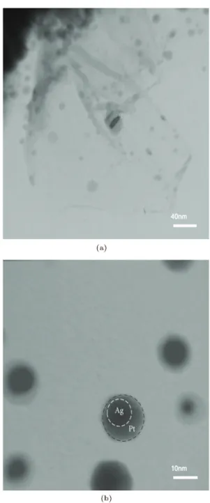
The HRTEM images of the synthesized electrocat-alyst of (1:3) Ag@Pt/rGO are displayed in Figure 1(a) and (b) at low and high magnications, respectively. The particle size, morphology, and dispersion status of this material were further analyzed in these images. It was revealed that the uniform distribution of high amounts of Ag@Pt nanoparticles upon rGO possessed rather spherical or elliptical shapes. According to this gure, Ag@Pt nanoparticles for 1:3 ratios formed with particle size diameters in the range of 7.5 to 16 nm at an average diameter of 9.2 nm. The electrical conductivity of the rGO was determined to be 3.8 E+1[S m 1]. This
was found to be in agreement with works of other researchers [56,58] for such materials. Due to these small sizes and well distribution of nanoparticles on the graphene surfaces and good electrical conductivity of the reduced graphene oxide support, the synthe-sized electrocatalysts were expected to demonstrate good catalytic activities and stabilities. Moreover, Figure 1(b), a high-resolution view of an HRTEM micrograph, demonstrates the core-shell structure of the Ag@Pt nanoparticles synthesized.
The XRD patterns of the prepared core-shell catalytic samples and the Ag/rGO material (for which the preparation procedure is provided in Section 2.1.3 above) are demonstrated in Figure 2. According to
Figure 1. HRTEM micrographs of Ag@Pt/rGO (1:3) prepared in this research: (a) Low and (b) high magnications.
Table 1. Structural characteristics of electrocatalysts with dierent Ag:Pt mass ratios supported on reduced graphene oxide and the commercial Pt/C determined in this work.
Electro-catalyst Nominal atomic ratio
Atomic ratio, ICP
Particle size (nm), XRD
Particle size (nm), HRTEM
Lattice parameter (nm)
Pt Ag Pt Ag
Pt/C (electrochem) 100 0 | | 2.9 | 0.3910
Ag@Pt/rGO
90 10 86 14 10 | 0.3938
75 25 73 27 10.3 9.2 0.3958
Figure 2. XRD patterns of GO electrocalatlysts with dierent Ag:Pt mass ratios prepared in this research and the commercial Pt/C.
these patterns, the synthesized Ag@Pt/rGO catalysts represent polycrystalline Pt diractions. The most intense peak of GO was displayed at around 2 of 11
corresponding to the water-bound intercalated oxidized graphite and oxygen functionality groups that made GO disappear. Moreover, in this venue, a new peak rose at around 2 = 26, which was observed in
the as-prepared graphene supporting NPs. This was associated with carbon material corresponding to the (002), indicating that GO was reduced successfully to the rGO. For the Pt supported upon carbon materi-als, the four diraction peaks at 2 values of 38.9,
46.5, 67.5, and 81.4 were observed. These are the
characteristics of the face-centered cubic (fcc) lattice of the Pt, which are attributed to (111), (200), (220), and (311), respectively. In addition, the Ag peaks were displayed at 2 = 32:2, 46.2, 67.4, and 76.7.
These are attributed to (111), (200), (220), and (311), respectively. These emphasized the existence of the fcc cubic crystalline planes of the Ag species. Such peaks are displayed (be it) rather weakly on the Ag/rGO spectrum in Figure 2. Hence, the Ag/rGO spectra indicated that Ag was indeed present in the current electrocatalytic system. Nonetheless, the provided XRD spectra of the Ag@Pt/rGO did not reveal the existence of the lone Ag species. These are attributed to a couple of factors as follows: i) Ag surface was covered up with the Pt species in the core-shell struc-ture and ii) Ag's amount (as depicted in the Ag/rGO spectra) was comparatively minute to that of the Pt material (even at a 1:1 ratio of the Ag@Pt catalyst). Thus, the 2 angles were signicantly shifted to lower and smaller negative values, and crystallinity of Ag was not distinct through the Ag@Pt supported upon the rGO spectra. In other words, the Ag surface in synthesized materials was mostly wrapped up by the Pt species, while the core-shell structure of nanoparticles was formed. The average crystallite size was estimated
by Scherrer's equation [59] for the diraction peak due to (111) and was determined through the following relationship:
d = 0:9(B2cos ) 1; (1)
where d is the average particle size (nm), B2 is the
full width of the diraction peak at half maximum in radians of the plane reection calculated by a Lorentzian function, is the X-ray wavelength (1.54A
for Cu K radiation), and is the angle stand at the position of the peak's maximum. The average crystallite size of the Ag@Pt catalyst was estimated, and the results are provided in Table 1. According to this table, the mean crystallite size of the Ag@Pt raised following the enhancement of its mass ratio of Pt:Ag.
The lattice parameter (afcc) values were
calcu-lated according to Vegard's law [60] for the synthesized electrocatalysts, and the outcomes are tabulated in Table 1. These results demonstrated that the lat-tice parameter of the synthesized electrocatalysts was larger than that of a lattice constant of 3.92 A of the Pt alone. Moreover, the insertion of Ag with a lattice constant of 4.08 A caused the Pt's lattice to expand. These results emphasized that Ag surface was mostly intricate due to the Pt; hence, a core-shell structure of the synthesized electrocatalyst was created. These out-comes superlatively conrmed the previously discussed XRD and HRTEM results in this paper.
At this point, one needs to distinguish between core-shell structures and alloy formations with regard to the prepared electrocatalyst in this research. This is considered as a two-fold concept. First, a number of evidence pieces are required for verifying a core-shell structure. Then, the discussion of the obtained results should be followed in order to distinguish between the alloy and core-shell structures. To begin with, through the open literature, it is well accepted that three pieces of evidence including the XRD, HRTEM, and lattice parameter evaluations may suciently verify the existence of core-shell structures [32,39,61,62]. In addition, the most important one of such evaluations is known to be the HRTEM analysis [40]. In this venue, the conclusion that is drawn through the current research regarding the formation of the core-shell struc-ture clearly fullls all the three aforementioned criteria. Then, to discuss the observed behavior of the prepared material, one should exercise care to make sure no alloy is formed instead of a core-shell structure. In this research, this scientic curiosity was overcome through the following arguments. If an alloyed structure (being an intertwined mixture of the two metals) of Ag and Pt was formed in the current research, its corresponding XRD peaks characterized through the 2 angles for the synthesized electrocatalyst would have provided two distinct groups of peaks relating to both Pt and Ag
elements or peaks located between those of alloying species. However, this is not the case in this study. Here, no Ag peak was observed through the XRD spectrum since this species acted as the core part being placed within the Pt shell. Furthermore, the 2 peak corresponding to the Pt species slightly shifted to a lower value near the one relating to that of the Pt element. Moreover, in the case of the second rationale concerning not having an alloy of Pt-Ag, one's attention is called to the obtained HRTEM image of the present research. Here, a clear display of two contrasting darker and lighter regions corresponding to Ag and Pt species is observed, respectively. Once again, if the synthesized material is an alloy of Pt and Ag, all active site spots displayed in the obtained HRTEM micrograph are dark due to the presence of both metallic elements. All these rationales, provided and emphasized upon elsewhere in the open literature, further support the conclusion of the formation of core-shell [63,64] structure reached in the present work.
Moreover, carbonyl and carboxylic as oxygenated groups upon the GO surface were in charge of adsorp-tion of Ag ions from the soluadsorp-tion through electrostatic interactions, and the addition of the reducing agent caused the reduction of such ions [65,66]. Moreover, the stronger interaction between Ag and Pt in comparison to the interaction between metal and the carbon-based surface of the support (i.e., rGO), as well as the face-centered cubic structure of both Pt and Ag crystallites, are all in favor of the growth of Pt on Ag surface rather than the reverse of it. All these rationales were sucient to justify the coverage of the Ag nano-particles by Pt, hence the formation of a core-shell structure in synthesized electrocatalysts [67]. Ultimately, the aforementioned form of the structure reasoned-out is mainly responsible for the behaviors displayed in the present research.
3.2. Electrochemical measurements
The electrochemical surface area (ECSA) provided an estimate of the number of electrochemically active sites accessible per unit mass of the electrocatalyst [68]. The ECSA is calculated by Eq. (2) [19], essentially attributed to the charges of H2 adsorption/desorption
peaks after deducting the charge from the double layer area in Cyclic Voltammograms (CVs) [69]. In other words:
ECSAH(cm2gPt 1) = QH(C cm 2)
:(210(C cmPt 2):L
Pt(gPt cm 2)) 1; (2)
where QH is the average integrated area, depicting the total charge with regard to hydrogen adsorp-tion/desorption on the Pt surface obtained by the CV method. Moreover, LPt represents platinum loading
on the electrode, and a constant value of 210 C cm 2 is determined by the charge required to oxidize
a monolayer of H2on a smooth platinum surface [70].
The ECSA is considered as a signicantly im-portant parameter to compare activities of dierent electrocatalysts. Furthermore, a fuel cell catalyst that possesses high activities is believed to have a high ECSA value. It seems worthy of mentioning that the ECSA is calculated according to the charges of H2 adsorption/desorption peaks. This parameter
evaluation is also based on COad oxidation charges
determined in a previously published work of these authors [71]. The results of the ECSA determinations of Ag@Pt materials understudied in this research are summarized in Table 2. These indicate that the ECSA of (1:3) Ag@Pt/rGO catalyst is 77.6 (m2 gPt 1) and
is taken to be the best Ag:Pt mass ratio prepared in this work. In other words, it is much larger than that of the commercial Pt/C and noticeably bigger than those of other synthesized electrocatalysts of dierent Pt:Ag mass ratios prepared in this research. In addition, as expected, the catalytic activity of the core-shell structure catalysts prepared is indeed higher than that of the commercial one. This is attributed to the comparatively extended bonding distances and the resulting modied charge transfer behavior from Ag to Pt and more uniformly dispersed particles, formed upon the rGO supports.
The cyclic voltammetry analyses of the prepared electrocatalysts with dierent mass ratios (of Pt:Ag) and a commercial Pt/C (of 10 wt.% metal content pur-chased from the Electrochem Inc.) and the synthesized Ag/rGO (with 10 wt% Ag content) were performed in
Table 2. Performance data of electrocatalysts with dierent Ag:Pt mass ratios and commercial Pt/C determined in this research.
Catalysts Metal loading (Wt%)
ECSA (m2gPt 1)
Onset potential (mv) vs. Ag/AgCl
Rct
( cm 2)
Pt Ag
Ag@Pt/rGO
9 1 68.3 695 92
3 1 77.6 754 61
1 1 47.2 608 234
Figure 3. Cyclic voltammograms of electrocalatlysts synthesized with dierent Ag:Pt mass ratios supported on the reduced graphene oxide and a commercial Pt/C in 0.5 M H2SO4 with a scan rate of 50 mVs 1under N2
atmosphere at 25C.
0.5 M H2SO4 solution under N2 atmosphere at 25C.
Results are shown in Figure 3. In the potential range of 0:2 to 1.1 V, hydrogen adsorption/desorption peaks of the Pt species are acquired at -0.2 to 0 V, while the oxidation and reduction of the Pt metal are done at 0.5 to 1.1 V. In addition, Figure 3 includes a voltam-mogram of lone Ag/rGO species, providing a better background comparison for the materials understudied. Obviously, the insertion of Ag onto the Pt lattice enhanced the extent of the Pt's active sites, exposed to the hydrogen stream (in the ORR) at the shell part of this structure. Thus, the characteristic hydrogen ad-sorption/desorption peaks of the electrocatalyst's core-shell structure were pronounced. On the other hand, increasing the incorporated amounts of Ag onto the Pt lattice from 2.5 to 5% transformed the crystalline structure of the Pt and reduced availability of the Pt active sites. Consequently, when Ag content grew, the characteristic hydrogen adsorption/desorption peaks became ill explained. Nonetheless, well-established features of the double-layer charging and the Pt ox-idation/reduction peaks were demonstrated through the obtained voltammograms along with the prevalent characteristics of the Pt nanoparticles observed in this research, which well emphasized the results previously revealed by other researchers [72].
Figure 4 depicts the Oxygen Reduction Reaction (ORR) results in O2 saturated solution by Linear
Sweep Voltammetric (LSV) scans at a rotation rate of 1,600 rpm and a sweep rate of 5 mV s 1 in 0.5 M
H2SO4 solution. This indeed provides Ag/rGO as a
contrast material, better reecting the performance improvement of the ORR due to the utilization of the Ag@Pt/rGO nano-catalyst synthesized in this research. This took place in the potential range of 1 to 0:2 V versus the Ag/AgCl reference electrode for dierent Ag:Pt ratios and the commercial Pt/C
electrocata-Figure 4. Polarization curves of the prepared electrocalatlysts with dierent Ag:Pt mass ratios supported on reduced graphene oxide and a Pt/C in oxygen saturated 0.5 M H2SO4 with a sweep rate of
5 mVs 1 and a rotation speed of 1600 rpm at 25C.
lysts. As shown in this gure, the electrochemical reaction seems to be under both kinetic and diusion control regimes in the range of 0.3-0.7 V, compared to Ag/AgCl. Moreover, the diusion-limiting currents were obtained in the potential region below 0.3 V. One notices that, in comparison to the Pt/C electrocatalyst, the ORR polarization curve of (1:3) Ag@Pt/rGO mate-rial exhibited a higher onset of the reduction potential. This behavior indicated that the core-shell structure in synthesized electrocatalysts aected the activity of the ORR reaction. On the other hand, the limiting current due to the Pt/C electrocatalyst was revealed to be 3.84 mA cm 2 (based upon the geometric area)
in the ORR. This parameter was enhanced to 5 mA cm 2 for the (1:3) Ag@Pt/rGO material. These
values indicated that the diusion-limiting currents were strongly aected by the core-shell structure and the supporting materials for the Pt catalyst. Moreover, the information provided in Table 2 further emphasizes the onset of the reduction potential value for the synthesized catalyst of the (1:3) Ag@Pt/rGO shifted 125 mV compared to that of the virgin Pt/C material. This occurred due to the surface oxide formed followed by its reduction in the aforementioned potential range. In addition, the enhancement of the open circuit potential of the (1:3) Ag@Pt/rGO catalyst under oxygen-saturated conditions, compared to that of the virgin commercial Pt/C material, was observed. This is attributed to the improved oxygen adsorption upon the synthesized electrocatalyst, which was also seen by other researchers, too [73]. However, the stronger adsorption energy of the oxygenated Pt species upon the surface of the pure Pt (i.e., the Pt/C), compared to that of the Ag@Pt/rGO catalyst, may have led to the desorption of the oxygenated Pt species more readily occurring from the Ag@Pt/rGO material [74]. According to the study of Yu et al. [39] on the Ag@Pt
core-shell structured surface for oxygen electroreduc-tion catalysts, the formed surface complexes were observed to catalyze the reaction through a dominant 4e reduction pathway from O2 to water or the 2e
pathway when it was reduced to H2O2. Fortunately,
the reduction pathway of 4e is favored for the ORR because of its high catalytic eciency for the PEMFC and the onset values of the electrode potentials for cat-alyzing the oxygen reduction, as demonstrated in this study. This is attributed to such surfaces being much more positive when the core-shell materials are utilized versus alone Pt species. Hence, the incorporation of such positive catalytic surfaces as fuel cell cathodes is indeed recommended.
For a quantitative analysis of the catalyzed ORR by the synthesized electrocatalysts developed in this work, the kinetic current (Jk) was calculated by the
measured current (J) and diusion limited current (Jd)
on a Rotating Disc Electrode (RDE). For this purpose, the Koutecky-Levich (K-L) equation [75] was utilized:
J 1= J 1
k + Jd1; (3)
where diusion limited current, Jd, might be expressed
through the following relationship:
Jd= 0:62 nF D0:66C 0:16w0:5; (4)
where n represents the overall transferred electron number, F is Faraday's constant (96,500 C mol 1),
C is the saturated concentration of oxygen in 0.5 M H2SO4 solution, is the electrocatalysts viscosity of
saturated O2 electrolyte, and w is the rotation rate.
If one utilized Eqs. (3) and (4) to Plot j 1(mA 1cm2)
versus w 0:5(ras 0:5s0:5), the overall electron transfer
number (n) for the synthesized materials in the ORR might be determined.
The resulting Koutecky-Levich (K-L) behaviors of all the prepared electrocatalysts at 0.3 V versus Ag/AgCl potential and the electron transfer number (n) in the overall reduction process are tabulated in Table 3. The n value for the (1:3) Ag@Pt/rGO electrocatalyst was higher than other synthesized mass ratios of the Ag@Pt catalysts and the commercial Pt/C
material. The n value of about 4 indicates oxygen reduction on the surface of the core-shell structure nanoparticles, derived from the water direct formation via the 4e pathway of Eq. (5) [76]:
O2+ 4H++ 4e $ 2H2O: (5)
Moreover, this pathway for the (1:3) Ag@Pt/rGO pro-vided the most eciently promoted catalytic activity in the ORR process. Nonetheless, it did not aect the typical ORR mechanism.
Next, the Electrochemical Impedance Spec-troscopy (EIS) technique was performed to measure the frequency dependence of the impedance of a PEM fuel cell. To this end, a small sinusoidal AC potential is utilized as a perturbation signal to the cell followed by evaluating the current response. This diagnostic investigation was done in order to obtain a better un-derstanding of the eect of electrochemical behavior of the undertaken system to analyze the electron transfer kinetics, thus assessing the microscopic information about the fuel cell and providing a model for the understudied system with an appropriate Equivalent Circuit (EC). Moreover, this helped determine the electrochemical parameters of the system. The EIS was accomplished for the synthesized electrocatalysts and commercial Pt/C in the frequency range of 10 kHz to 0.01 Hz. The in-situ AC impedance spectra of a PEM fuel cell operated at room temperature and ambient pressure of dierent synthesized catalysts at 0.5 V, compared to the Ag/AgCl electrode shown in Figure 5. There are two semicircles observed on these spectra: one at a high-frequency domain and the other at a low-frequency domain, similar to what has been previously presented in another research for a PEM fuel cell [77]. According to these gures, by employing the Luggin capillary technique, the ohmic resistance of the fuel cell is determined by the intercept of the high-frequency domain on the real axis. Nonetheless, this eect was insignicant compared to that of the charge-transfer (Rct) shown through the arc diameter. Moreover, the
rst semicircle demonstrates the fuel cell reaction kinet-ics supplied to the cathodic ORR processes, while the
Table 3. Koutecky-Levich data from j 1(mA 1cm2) versus w 1=2(ras 1=2s1=2) of the electrocatalyst with dierent Ag:Pt
mass ratios and commercial Pt/C.
Catalysts Metal loading
(Wt%) Slope R2 n
Pt Ag
Ag@Pt/rGO
9 1 2.52 0.998 3.97
3 1 2.43 0.9977 4
1 1 2.66 0.999 3.91
Figure 5. EIS Nyquist plots of electrocalatlysts with dierent prepared Ag:Pt atomic ratios supported on reduced graphene oxide and a commercial Pt/C in oxygen saturated 0.5 M H2SO4 at 0.5 V versus Ag/AgCl. The
frequencies ranged from 10 kHz to 0.01 Hz, and schematic representation of the equivalent circuit for corresponding EIS plots, driven by Zveiw software for the (1:3)
Ag@Pt/rGO, was inserted. Rs: electrolyte resistance, Rct:
charge transfer resistance, and CPE: Constant-Phase Element.
second semicircle represents the mass transfer process that contributes to the diusion of oxygen on the Pt active surfaces within the catalyst layers. Further-more, all the Nyquist plots of the impedance spectra had nearly similar semi-circular shapes with dierent arc diameters. In addition, the proposed equivalent circuit was utilized to simulate the impedance data, as inserted in Figure 5. In this circuit, R represents the high-frequency ohmic resistance. In addition, due to the porous nature of the utilized electrodes, the double-layer capacitance was distributed between the ohmic and Faradic processes while expressed as the Constant-Phase Elements (CPE) in this equivalent circuit model [78]. Rctis the charge transfer resistance,
and the sum of the charge transfer and diusion resistances provided polarization resistance. The deter-mined charge transfer resistances (Rct) were extracted
by tting the EIS plots using the Z-view software, as summarized in Table 2. It was observed that Rctvalues
increased in order of (1:3), (1:9), and (1:1) Ag@Pt/rGO material being in good agreement with the CV analysis provided earlier in this paper. As shown in Table 2, the Rct value of the (1:3) Ag@Pt/rGO electrocatalyst
was found to be the lowest, and the resistance for the (1:1) Ag@Pt/rGO was too high in comparison with other Ag:Pt mass ratio electrodes synthesized in this work. When the amount of Ag increased from 1 to 2.5%, Rctwas enhanced; however, a further increment
to about 5% in the catalyst caused Rct to reduce
signicantly. Moreover, the impedance arc diameter of the (1:3) Ag@Pt/rGO material was smaller than others, indicating a higher electrocatalytic activity
for this electrode [3,71]. Thus, the experimentally determined best ratio of the Ag:Pt in this research was 1:3 and, also, conrmed by other analyses such as CV and LSV data, provided earlier above.
On the other hand, the ECSA is considered to be an essential factor in characterizing a PEMFC cata-lyst undergoing Accelerated Durability Tests (ADT). As previously mentioned, larger ECSA implies the availability of more active sites for catalysis, and the loss of ECSA leads to the performance degradation of the PEMFCs [40]. For this purpose, the cyclic voltammetry was performed in the potential range of
0:25 to 1.1 V at a scan rate of 50 mVs 1in N
2purged
0.5 M H2SO4 solution at room temperature [79]. The
degradations of the ECSA plotted in Figure 6 are nor-malized with respect to the initial amounts in a manner similar to the previously performed studies [79,80]. Upon the enhancement of the number of cycles, as expected, the ECSA of the Pt/C and Ag@Pt/rGO catalysts was reduced. More importantly, according to this gure, the durability of the commercial Pt/C material was considerably lower than that of the core-shell structure of Ag@Pt/rGO prepared in this work. In other words, after 2,000 cycles, only 12.7% of the initial ECSA of the Pt/C remained, whereas, for the prepared core-shell structured electrocatalysts of (1:3), (1:9), and (1:1) Ag@Pt/rGO, 72, 54, and 32% of the initial ECSA remained after many cycles. It was also evident that the commercial Pt/C electrocatalyst had lower stability than the synthesized core-shell struc-tured materials due to the signicant reduction of the Pt's active surface area by the dissolution, aggregation, and perhaps sintering of the Pt nanoparticles that occurred. The main reason for this higher stability of prepared materials is indeed the core-shell preparation idea of them. Based upon the dierences in the lattice parameters of the core and the shell (discussed above), internal stress engendered these materials.
Figure 6. Normalized ECSAs of the prepared electrocalatlysts with dierent Ag:Pt mass ratios supported on reduced graphene oxide and a commercial Pt/C in 0.5 M H2SO4 versus the cycle number.
Furthermore, by utilizing the same crystal structure of materials undertaken in this study, if the core lattice parameter is larger than that of the shell one, the chemical potential of the Pt on the shell side becomes smaller than that of the virgin Pt. This means that the propensity for the catalyst degradation reduced. Hence, its stability was enhanced. Thus, a major consequence of these obtained results is that the (1:3) Ag@Pt/rGO catalyst represented a higher activity and durability amongst the understudied materials in this work. It is implied that this catalyst might be considered as a rather auspicious cathode material for the oxygen reduction reaction in PEM fuel cells. 3.3. Performance of the catalyst measured in
PEM fuel cell tests
The single fuel cell tests were performed upon the pre-pared (1:3) Ag@Pt/rGO and Pt/C catalysts operated at 80C and 1.5 bars under 90% Relative Humidity
(RH) with feed ow rates of 300 ml min 1 for the
hydrogen and 500 ml min 1 for the pure oxygen. To
record the polarization curves, the cell was retained at each current density for 5 min [81]. In this venue, performances of the commercial Pt/C (MEA-1) and (1:3) Ag@Pt/rGO (MEA-2) catalysts as cathodes in an actual fuel cell were reported. The polarization and power density curves of MEA-1 and MEA-2 under similar conditions as the V- and P-I plots of PEMFCs are presented in Figure 7. As shown in this gure, due to the mass transport limitations at the high current density area, the fuel cell performance rapidly dropped to 246 and 405 mWcm 2 for MEA-1 and
MEA-2, respectively. These values imply that the mass transport losses of MEA-2 were considerably lower than those of MEA-1. This is attributed to the higher surface area and better electrical and mechanical properties of the graphene, leading to better mass transfer of oxygen and water compared to that of the
Figure 7. Polarization and power density curves of single PEMFCs with MEA-1 and MEA-2 prepared in this work. MEA active area: 6.25 cm2; anode gas ow rate: 300 mL
min 1; cathode gas ow rate: 500 mL min 1; and gas
pressure at the back of the electrodes: 1.5 atm.
commercial Pt/C material. A similar conclusion was obtained by other researchers, too [82].
Once more, it is a foregone conclusion that the performance of (1:3) Ag@Pt/rGO is better than that of the commercial Pt/C in the whole range of the current densities investigated. Moreover, the maximum established power density of the core-shell synthesized electrocatalyst was 576 mWcm 2, which is 55% higher
than that of the commercial Pt/C. Furthermore, the Open Circuit Voltage (OCV) of MEA-2 was consid-erably higher than that of MEA-1. In this regard, since the OCV is associated with the concentration of fuel present on the cathode side, its higher value indicates the occurrence of lower fuel crossover. Fuel crossover corresponds to the diusion of un-reacted fuel from the anode to the cathode across the Naon membrane. Such fuel crossover led to major drawbacks in terms of the creation of a mixed potential eect and poisoning of the Pt electrocatalyst at the cathode. This phenomenon remarkably reduced the cell performance and fuel utilization eciency. Accordingly, MEA-2 substantially reduced the fuel crossover, thus enhanc-ing the eciency and stability of the PEMFCs. In addition, the reduced graphene oxide enacting as the catalyst support positively aected the reduction of the fuel crossover across the membrane in the single cell tests undertaken. On the other hand, as demon-strated in Figure 7, the fuel cell performance in the ohmic and concentration resistance regions for MEA-2 was superior to that for MEA-1. Ultimately, these outcomes further were conrmed, and emphasized that the respective electrocatalyst of MEA-2 might be a propitious candidate as a cathode for the PEM fuel cell applications.
4. Conclusion
This research investigated a facile synthesis of well dispersed Ag@Pt coshell NPs supported upon re-duced graphene oxide through an ultrasonic treatment method with dierent Ag:Pt mass ratios. Initially, sil-ver nanoparticles were decorated upon the graphene ox-ide by utilizing the NaBH4as a reducing agent. Then,
Pt loading upon the surface of silver nanoparticles was accomplished ultrasonically. Next, physical and electrochemical characterization tests and performance evaluations of Ag@Pt/rGO core-shell electrocatalyst for the ORR in a PEM fuel cell were undertaken. The average size of the Ag@Pt nanoparticles was about 9.2-10.7 nm for dierent synthesized materials with various mass ratios of Ag:Pt. This size was enhanced by increasing amounts of the Ag species. The HRTEM and XRD results emphasized the core-shell structure of the prepared electrocatalyst. According to the ob-tained results determined through the CV techniques, the Ag@Pt/rGO material with a Ag:Pt mass ratio of
1:3 possessed the largest electrochemical surface area of 77.6 m2g 1. Moreover, the resulting impedance arc
di-ameter for this mass ratio was turned out to be smaller than those of others. This revealed a higher electrocat-alytic activity for this electrode determined through the EIS measurements. Furthermore, Koutecky-Levich's (K-L) analysis revealed that the 4e transfer pathway for this electrocatalyst provided the most eciently promoted catalytic activity route towards the ORR process. It is considered noteworthy to mention that the aforementioned mass ratio possessed the highest stability amongst all other synthesized Ag:Pt mass ratios and the commercial Pt/C electrocatalysts.
Ultimately, the performance of the optimal (1:3) Ag@Pt/rGO as a cathode was inquired in a PEM single cell and was compared to that of a commercial Pt/C material. The maximum power density of the MEA based upon the aforementioned electrocatalyst with Ag:Pt mass ratio of 1:3 was revealed to be 55% higher than that of the one prepared with a commercial Pt/C. In addition, the higher OCV value resulting from the MEA evaluations in single cell tests for this synthesized species led to lower fuel crossover compared to a commercial Pt/C. This emphasized that the former material performance was superior. Thus, due to all evidence pieces obtained in this research, it seemed logical to conclude that the (1:3) Ag@Pt/rGO electrocatalyst might be considered a desirable cathode candidate for a PEM fuel cell, producing the sought electrochemical energy.
Nomenclature
d Average particle size (nm)
B2 Full width of the diraction peak at
half maximum (rad) X-ray wavelength (A)
Angle stand at the position (rad) afcc Lattice parameter (A)
QH Average integrated area (C cm 2)
LP t Platinum loading on the electrode (gPt
cm 2)
Jk Kinetic current (A)
J Current (A)
Jd Diusion limited current (A)
n Overall transferred electron number F Faraday's constant
C Saturated concentration of oxygen in 0.5 M H2SO4 solution (mol m 3)
Kinetic viscosity of saturated O2
electrolyte (m2 s 1)
w Rotation rate (rad s 1)
References
1. De Bruijn, F.A., Dam, V.A.T., and Janssen, G.J.M. \Review: durability and degradation issues of PEM fuel cell components", Fuel Cells, 8(1), pp. 3-22 (2008).
2. Zhang, X. and Chen, J. \Performance evaluation and parametric optimization of a proton exchange mem-brane fuel cell/heat-driven heat pump hybrid system", Fuel Cells, 12(3), pp. 313-319 (2012).
3. Gharibi, H., Golmohammadi, F., and Kheirmand, M. \Palladium/cobalt coated on multi-walled carbon nanotubes as an electro-catalyst for oxygen reduction reaction in passive direct methanol fuel cells", Fuel Cells, 13(6), pp. 987-1004 (2013).
4. San Martn, J.I., Zamora, I., Aperribay, V., San Martn, J.J., Egua, P., and Torres, E. \Performance analysis of PEM fuel cells with dierent electrical loads", Fuel Cells, 14(2), pp. 312-324 (2014).
5. Afsahi, F., Mathieu-Potvin, F., and Kaliaguine, S. \Impact of ionomer content on proton exchange mem-brane fuel cell performance", Fuel Cells, 16(1), pp. 107-125 (2016).
6. Sui, S., Wang, X., Zhou, X., Su, Y., Riat, S., and Liu, C. \A comprehensive review of Pt electrocatalysts for the oxygen reduction reaction: Nanostructure, activity, mechanism and carbon support in PEM fuel cells", J. Mater. Chem. A, 5(5), pp. 1808-1825 (2017).
7. Cantillo, N.M., Goenaga, G.A., Gao, W., Williams, K., Neal, C.A., Ma, S., More, K.L., and Zawodzinski, T.A. \Investigation of a microporous iron(iii) porphyrin framework derived cathode catalyst in PEM fuel cells", J. Mater. Chem. A, 4(40), pp. 15621-15630 (2016).
8. Chaisubanan, N., Maniwan, W., and Hunsom, M. \Ef-fect of heat-treatment on the performance of PtM/C (M = Cr, Pd, Co) catalysts towards the oxygen reduction reaction in PEM fuel cell", Energy, 127, pp. 454-461 (2017).
9. Zamel, N. and Li, X. \A parametric study of multi-phase and multi-species transport in the cathode of PEM fuel cells", Int. J. Energy Res., 32(8), pp. 698-721 (2008).
10. Kadirgan, F., Kannan, A.M., Atilan, T., Beyhan, S., Ozenler, S.S., Suzer, S., and Yorur, A. \Carbon supported nano-sized Pt-Pd and Pt-Co electrocata-lysts for proton exchange membrane fuel cells", Int. J. Hydrogen Energy, 34(23), pp. 9450-9460 (2009).
11. Salgado, J.R.C., Antolini, E., and Gonzalez, E.R. \Carbon supported Pt70Co30 electrocatalyst prepared by the formic acid method for the oxygen reduction reaction in polymer electrolyte fuel cells", J. Power Sources, 141(1), pp. 13-18 (2005).
12. Fang, B., Luo, J., Njoki, P.N., Loukrakpam, R., Wanjala, B., Hong, J., Yin, J., Hu, X., Last, J., and Zhong, C.-J. \Nano-engineered PtVFe catalysts in proton exchange membrane fuel cells: Electrocatalytic performance", Electrochim. Acta, 55(27), pp. 8230-8236 (2010).
13. Colon-Mercado, H.R., Kim, H., and Popov, B.N. \Durability study of Pt3Ni1 catalysts as cathode in PEM fuel cells", Electrochem. Commun., 6(8), pp. 795-799 (2004).
14. Salome, S., Ferraria, A.M., Botelho do Rego, A.M., Alcaide, F., Savadogo, O., and Rego, R. \Enhanced activity and durability of novel activated carbon-supported PdSn heat-treated cathode catalyst for polymer electrolyte fuel cells", Electrochim. Acta, 192, pp. 268-282 (2016).
15. He, C. and Tao, J. \Pt loaded two-dimensional TaC-nanosheet/graphene hybrid as an ecient and durable electrocatalyst for direct methanol fuel cells", J. Power Sources, 324, pp. 317-324 (2016).
16. Zhong, H., Zhang, H., Liu, G., Liang, Y., Hu, J., and Yi, B. \A novel non-noble electrocatalyst for PEM fuel cell based on molybdenum nitride", Electrochem. Commun., 8(5), pp. 707-712 (2006).
17. Colon-Mercado, H.R. and Popov, B.N. \Stability of platinum based alloy cathode catalysts in PEM fuel cells", J. Power Sources, 155(2), pp. 253-263 (2006).
18. Ma, Y., Zhang, H., Zhong, H., Xu, T., Jin, H., and Geng, X. \High active PtAu/C catalyst with core-shell structure for oxygen reduction reaction", Catal. Commun., 11(5), pp. 434-437 (2010).
19. Saha, M.S., Li, R., Cai, M., and Sun, X. \Nanowire-based three-dimensional hierarchical core/shell het-erostructured electrodes for high performance proton exchange membrane fuel cells", J. Power Sources, 185(2), pp. 1079-1085 (2008).
20. Cai, Z., Zhang, D., Cheng, K., Song, C., Li, Y., Ye, K., Yan, P., Cao, D., and Wang, G. \Platinum nanoparticles anchored on TiO2/C nanowires as a high performance catalyst for hydrogen peroxide eletrore-duction", Fuel Cells, 16(5), pp. 646-651 (2016).
21. Di Noto, V. and Negro, E. \Development of nano-electrocatalysts based on carbon nitride supports for the ORR processes in PEM fuel cells", Electrochim. Acta, 55(26), pp. 7564-7574 (2010).
22. Tedsree, K., Li, T., Jones, S., Chan, C.W.A., Yu, K.M.K., Bagot, P.A.J., Marquis, E.A., Smith, G.D.W., and Tsang, S.C.E. \Hydrogen production from formic acid decomposition at room temperature using a Ag-Pd core-shell nanocatalyst", Nat. Nanotechnol., 6, p. 302 (2011).
23. Strasser, P., Koh, S., Anniyev, T., Greeley, J., More, K., Yu, C., Liu, Z., Kaya, S., Nordlund, D., Oga-sawara, H., Toney, M.F., and Nilsson, A. \Lattice-strain control of the activity in dealloyed core-shell fuel cell catalysts", Nat. Chem., 2(6), pp. 454-460 (2010).
24. Wang, G., Guan, J., Xiao, L., Huang, B., Wu, N., Lu, J., and Zhuang, L. \Pd skin on AuCu intermetal-lic nanoparticles: A highly active electrocatalyst for oxygen reduction reaction in alkaline media", Nano Energy, 29, pp. 268-274 (2016).
25. Trongchuankij, W., Pruksathorn, K., and Hunsom, M. \Preparation of a high performance Pt-Co/C electro-catalyst for oxygen reduction in PEM fuel cell via a combined process of impregnation and seeding", Appl. Energy, 88(3), pp. 974-980 (2011).
26. Vasile, N.S., Doherty, R., Monteverde Videla, A.H.A., and Specchia, S. \3D multi-physics modeling of a gas diusion electrode for oxygen reduction reaction for electrochemical energy conversion in PEM fuel cells", Appl. Energy, 175, pp. 435-450 (2016).
27. Esfandiari, A., Kazemeini, M., and Bastani, D. \Syn-thesis, characterization and performance determina-tion of an Ag@Pt/C electrocatalyst for the ORR in a PEM fuel cell", Int. J. Hydrogen Energy, 41(45), pp. 20720-20730 (2016).
28. Van Schalkwyk, F., Pattrick, G., Olivier, J., Conrad, O., and Blair, S. \Development and scale up of enhanced ORR Pt-based catalysts for PEMFCs", Fuel Cells, 16(4), pp. 414-427 (2016).
29. Holton, O.T. and Stevenson, J.W. \The role of plat-inum in proton exchange membrane fuel cells", Platin. Met. Rev., 57(4), pp. 259-271 (2013).
30. Nrskov, J.K., Rossmeisl, J., Logadottir, A., Lindqvist, L., Kitchin, J.R., Bligaard, T., and Jonsson, H. \Origin of the overpotential for oxygen reduction at a fuel-cell cathode", J. Phys. Chem. B, 108(46), pp. 17886-17892 (2004).
31. Lin, R., Cao, C., Zhao, T., Huang, Z., Li, B., Wieckowski, A., and Ma, J. \Synthesis and applica-tion of core-shell Co@Pt/C electrocatalysts for proton exchange membrane fuel cells", J. Power Sources, 223, pp. 190-198 (2013).
32. Kristian, N., Yu, Y., Lee, J.-M., Liu, X., and Wang, X. \Synthesis and characterization of Cocore-Ptshell
electrocatalyst prepared by spontaneous replacement reaction for oxygen reduction reaction", Electrochim. Acta, 56(2), pp. 1000-1007 (2010).
33. Chen, T.-Y., Lee, G.-W., Liu, Y.-T., Liao, Y.-F., Huang, C.-C., Lin, D.-S., and Lin, T.-L. \Heterojunc-tion connement on the atomic structure evolu\Heterojunc-tion of near monolayer core-shell nanocatalysts in redox reactions of a direct methanol fuel cell", J. Mater. Chem. A, 3(4), pp. 1518-1529 (2015).
34. Wongkaew, A., Zhang, Y., Tengco, J.M.M., Blom, D.A., Sivasubramanian, P., Fanson, P.T., Regalbuto, J.R., and Monnier, J.R. \Characterization and evalu-ation of Pt-Pd electrocatalysts prepared by electroless
deposition", Appl. Catal. B Environ., 188, pp. 367-375 (2016).
35. Chatenet, M., Genies-Bultel, L., Aurousseau, M., Durand, R., and Andolfatto, F. \Oxygen reduction on silver catalysts in solutions containing various concentrations of sodium hydroxide - comparison with platinum", J. Appl. Electrochem., 32(10), pp. 1131-1140 (2002).
36. Yang, J., Lee, J.Y., Chen, L.X., and Too, H.-P. \A phase-transfer identication of core-shell structures in Ag-Pt nanoparticles", J. Phys. Chem. B, 109(12), pp. 5468-5472 (2005).
37. Neyerlin, K.C., Srivastava, R., Yu, C., and Strasser, P. \Electrochemical activity and stability of dealloyed Pt-Cu and Pt-Cu-Co electrocatalysts for the oxygen reduction reaction (ORR)", J. Power Sources, 186(2), pp. 261-267 (2009).
38. Yu, S., Lou, Q., Han, K., Wang, Z., and Zhu, H. \Syn-thesis and electrocatalytic performance of MWCNT-supported Ag@Pt core-shell nanoparticles for ORR", Int. J. Hydrogen Energy, 37(18), pp. 13365-13370 (2012).
39. Yu, S., Liu, R., Yang, W., Han, K., Wang, Z., and Zhu, H. \Synthesis and electrocatalytic performance of MnO2-promoted Ag@Pt/MWCNT electrocatalysts
for oxygen reduction reaction", J. Mater. Chem. A, 2(15), pp. 5371-5378 (2014).
40. Koh, J.-H., Abbaraju, R., Parthasarathy, P., and Virkar, A.V. \Design and synthesis of degradation-resistant core-shell catalysts for proton exchange mem-brane fuel cells", J. Power Sources, 261, pp. 271-277 (2014).
41. Gasteiger, H.A., Kocha, S.S., Sompalli, B., and Wag-ner, F.T. \Activity benchmarks and requirements for Pt, Pt-alloy, and non-Pt oxygen reduction catalysts for PEMFCs", Appl. Catal. B Environ., 56(1), pp. 9-35 (2005).
42. Yu, X. and Ye, S. \Recent advances in activity and durability enhancement of Pt/C catalytic cathode in PEMFC: Part I. Physico-chemical and electronic in-teraction between Pt and carbon support, and activity enhancement of Pt/C catalyst", J. Power Sources, 172(1), pp. 133-144 (2007).
43. Du, L., Shao, Y., Sun, J., Yin, G., Liu, J., and Wang, Y. \Advanced catalyst supports for PEM fuel cell cathodes", Nano Energy, 29, pp. 314-322 (2016).
44. Yu, X. and Ye, S. \Recent advances in activity and durability enhancement of Pt/C catalytic cathode in PEMFC: Part II: Degradation mechanism and dura-bility enhancement of carbon supported platinum cat-alyst", J. Power Sources, 172(1), pp. 145-154 (2007).
45. Wang, J., Yin, G., Shao, Y., Zhang, S., Wang, Z., and Gao, Y. \Eect of carbon black support corrosion on the durability of Pt/C catalyst", J. Power Sources, 171(2), pp. 331-339 (2007).
46. Fashedemi, O.O., Miller, H.A., Marchionni, A., Vizza, F., and Ozoemena, K.I. \Electro-oxidation of ethylene glycol and glycerol at palladium-decorated FeCo@Fe core-shell nanocatalysts for alkaline direct alcohol fuel cells: functionalized MWCNT supports and impact on product selectivity", J. Mater. Chem. A, 3(13), pp. 7145-7156 (2015).
47. He, C. and Shen, P.K. \Synthesis of the nitrogen-doped carbon nanotube (NCNT) bouquets and their electrochemical properties", Electrochem. Commun., 35, pp. 80-83 (2013).
48. Shao, Y., Zhang, S., Kou, R., Wang, X., Wang, C., Dai, S., Viswanathan, V., Liu, J., Wang, Y., and Lin, Y. \Noncovalently functionalized graphitic meso-porous carbon as a stable support of Pt nanoparticles for oxygen reduction", J. Power Sources, 195(7), pp. 1805-1811 (2010).
49. Sebastian, D., Calderon, J.C., Gonzalez-Exposito, J.A., Pastor, E., Martnez-Huerta, M.V., Suelves, I., Moliner, R., and Lazaro, M.J. \Inuence of carbon nanober properties as electrocatalyst support on the electrochemical performance for PEM fuel cells", Int. J. Hydrogen Energy, 35(18), pp. 9934-9942 (2010).
50. He, D., Cheng, K., Peng, T., Pan, M., and Mu, S. \Graphene/carbon nanospheres sandwich supported PEM fuel cell metal nanocatalysts with remarkably high activity and stability", J. Mater. Chem. A, 1(6), pp. 2126-2132 (2013).
51. He, C. and Shen, P.K. \Pt loaded on truncated hexagonal pyramid WC/graphene for oxygen reduction reaction", Nano Energy, 8, pp. 52-61 (2014).
52. Antolini, E. \Graphene as a new carbon support for low-temperature fuel cell catalysts", Appl. Catal. B Environ., 123-124, pp. 52-68 (2012).
53. Huang, H., Chen, H., Sun, D., and Wang, X. \Graphene nanoplate-Pt composite as a high perfor-mance electrocatalyst for direct methanol fuel cells", J. Power Sources, 204, pp. 46-52 (2012).
54. He, C., Tao, J., He, G., and Shen, P.K. \Ultrasmall molybdenum carbide nanocrystals coupled with re-duced graphene oxide supported Pt nanoparticles as enhanced synergistic catalyst for methanol oxidation reaction", Electrochim. Acta, 216, pp. 295-303 (2016).
55. Hummers, W.S. and Oeman, R.E. \Preparation of graphitic oxide", J. Am. Chem. Soc., 80(6), p. 1339 (1958).
56. Shin, H.-J., Kim, K.K., Benayad, A., Yoon, S.-M., Park, H.K., Jung, I.-S., Jin, M.H., Jeong, H.-K., Kim, J.M., Choi, J.-Y., and Lee, Y.H. \Ecient reduction of graphite oxide by sodium borohydride and its eect on electrical conductance", Adv. Funct. Mater., 19(12), pp. 1987-1992 (2009).
57. Gharibi, H., Yasi, F., Kazemeini, M., Heydari, A., and Golmohammadi, F. \Fabrication of MEA based
on sulfonic acid functionalized carbon supported plat-inum nanoparticles for oxygen reduction reaction in PEMFCs", RSC Adv., 5(104), pp. 85775-85784 (2015).
58. Pei, S. and Cheng, H.-M. \The reduction of graphene oxide", Carbon N.Y., 50(9), pp. 3210-3228 (2012).
59. Shao, M.-H., Sasaki, K., and Adzic, R.R. \Pd-Fe nanoparticles as electrocatalysts for oxygen reduc-tion", J. Am. Chem. Soc., 128(11), pp. 3526-3527 (2006).
60. Lim, D.-H., Choi, D.-H., Lee, W.-D., and Lee, H.-I. \A new synthesis of a highly dispersed and CO tolerant PtSn/C electrocatalyst for low-temperature fuel cell; its electrocatalytic activity and long-term durability", Appl. Catal. B Environ., 89(3), pp. 484-493 (2009).
61. Pech-Pech, I.E., Gervasio, D.F., and Perez-Robles, J.F. \Nanoparticles of Ag with a Pt and Pd rich surface supported on carbon as a new catalyst for the oxygen electroreduction reaction (ORR) in acid electrolytes: Part 2", J. Power Sources, 276, pp. 374-381 (2015).
62. Nguyen, T.-T., Pan, C.-J., Liu, J.-Y., Chou, H.-L., Rick, J., Su, W.-N., and Hwang, B.-J. \Functional palladium tetrapod core of heterogeneous palladium-platinum nanodendrites for enhanced oxygen reduction reaction", J. Power Sources, 251, pp. 393-401 (2014).
63. Endo, K., Nakamura, K., Katayama, Y., and Miura, T. \Pt-Me (Me = Ir, Ru, Ni) binary alloys as an ammonia oxidation anode", Electrochim. Acta, 49(15), pp. 2503-2509 (2004).
64. Yan, W., Tang, Z., Wang, L., Wang, Q., Yang, H., and Chen, S. \PdAu alloyed clusters supported by carbon nanosheets as ecient electrocatalysts for oxygen reduction", Int. J. Hydrogen Energy, 42(1), pp. 218-227 (2017).
65. Goncalves, G., Marques, P.A.A.P., Granadeiro, C.M., Nogueira, H.I.S., Singh, M.K., and Gracio, J. \Sur-face modication of graphene nanosheets with gold nanoparticles: The role of oxygen moieties at graphene surface on gold nucleation and growth", Chem. Mater., 21(20), pp. 4796-4802 (2009).
66. Tang, X.-Z., Li, X., Cao, Z., Yang, J., Wang, H., Pu, X., and Yu, Z.-Z. \Synthesis of graphene decorated with silver nanoparticles by simultaneous reduction of graphene oxide and silver ions with glucose", Carbon N.Y., 59, pp. 93-99 (2013).
67. Wang, R., Li, H., Feng, H., Wang, H., and Lei, Z. \Preparation of carbon-supported core@shell PdCu@PtRu nanoparticles for methanol oxidation", J. Power Sources, 195(4), pp. 1099-1102 (2010).
68. Qiu, J.-D., Wang, G.-C., Liang, R.-P., Xia, X.-H., and Yu, H.-W. \Controllable deposition of platinum nanoparticles on graphene as an electrocatalyst for direct methanol fuel cells", J. Phys. Chem. C, 115(31), pp. 15639-15645 (2011).
69. Girishkumar, G., Rettker, M., Underhile, R., Binz, D., Vinodgopal, K., McGinn, P., and Kamat, P. \Single-wall carbon nanotube-based proton exchange mem-brane assembly for hydrogen fuel cells", Langmuir, 21(18), pp. 8487-8494 (2005).
70. Sadeghi, S., Gharibi, H., and Golmohammadi, F. \Electrooxidations of ethanol and acetaldehyde using PtSn/C and PtSnO2/C catalysts prepared by a
mod-ied alcohol-reduction process", Sci. Iran., 22(6), pp. 2729-2735 (2015).
71. Amani, M., Kazemeini, M., Hamedanian, M., Pahla-vanzadeh, H., and Gharibi, H. \Investigation of methanol oxidation on a highly active and stable Pt-Sn electrocatalyst supported on carbon-polyaniline composite for application in a passive direct methanol fuel cell", Mater. Res. Bull., 68, pp. 166-178 (2015).
72. Lee, K., Zhang, J., Wang, H., and Wilkinson, D.P. \Progress in the synthesis of carbon nanotube- and nanober-supported Pt electrocatalysts for PEM fuel cell catalysis", J. Appl. Electrochem., 36(5), pp. 507-522 (2006).
73. Wei, Y.-C., Liu, C.-W., Lee, H.-W., Chung, S.-R., Lee, S.-L., Chan, T.-S., Lee, J.-F., and Wang, K.-W. \Synergistic eect of Co alloying and surface oxidation on oxygen reduction reaction performance for the Pd electrocatalysts", Int. J. Hydrogen Energy, 36(6), pp. 3789-3802 (2011).
74. Zhao, J. and Manthiram, A. \Preleached Pd-Pt-Ni and binary Pd-Pt electrocatalysts for oxygen reduction reaction in proton exchange membrane fuel cells", Appl. Catal. B Environ., 101(3), pp. 660-668 (2011).
75. Liu, R., Wu, D., Feng, X., and Mullen, K. \Nitrogen-doped ordered mesoporous graphitic arrays with high electrocatalytic activity for oxygen reduction", Angew. Chemie, 122(14), pp. 2619-2623 (2010).
76. Wroblowa, H.S., Pan, Y.C., and Razumney, G. \Elec-troreduction of oxygen: A new mechanistic criterion", J. Electroanal. Chem. Interfacial Electrochem., 69(2), pp. 195-201 (1976).
77. Zhang, J., Tang, Y., Song, C., and Zhang, J. \Polybenzimidazole-membrane-based PEM fuel cell in the temperature range of 120-200C", J. Power
Sources, 172(1), pp. 163-171 (2007).
78. Yuan, X. Z., Song, C., Wang, H., and Zhang, J., Electrochemical Impedance Spectroscopy in PEM Fuel Cells: Fundamentals and Applications, Springer Lon-don (2010).
79. Gharibi, H., Sadeghi, S., and Golmohammadi, F. \Electrooxidation of ethanol on highly active and stable carbon supported PtSnO2 and its application
in passive direct ethanol fuel cell: Eect of tin oxide synthesis method", Electrochim. Acta, 190, pp. 1100-1112 (2016).
Y. \Durability investigation of carbon nanotube as catalyst support for proton exchange membrane fuel cell", J. Power Sources, 158(1), pp. 154-159 (2006).
81. Yu, P., Pemberton, M., and Plasse, P. \PtCo/C cathode catalyst for improved durability in PEMFCs", J. Power Sources, 144(1), pp. 11-20 (2005).
82. Seger, B. and Kamat, P.V. \Electrocatalytically ac-tive graphene-platinum nanocomposites. Role of 2-D carbon support in PEM fuel cells", J. Phys. Chem. C, 113(19), pp. 7990-7995 (2009).
Biographies
Ali Esfandiari received his PhD degree from Sharif University of Technology in Iran in 2017 in the Thermo-Kinetic and Catalysis group in general and Electro-catalysis in particular within the chemical engineering eld. His research interests include the preparation and characterization of activated carbon, core-shell struc-ture for electrocatalysis and modeling of chemical and
physical kinetics, and adsorption/desorption paths. Furthermore, investigating supports such as CNT, graphene, MWCNT, and Vulcan types for catalysts and sorbents purposes is of his interest, too.
Mohammad Kazemeini graduated from The UIC in the eld of Catalysis and Surface Science, USA, 1991. Ever since, he joined the Chemical and Petroleum Engi-neering Department at Sharif University of Technology where he currently holds a (full) Professor position. His research interests include the preparation, characteri-zation and physiochemical evaluations; mathematical modeling of chemical and physical kinetics of regular core-shell and magnetic catalysts; the investigation of alumina, carbons (CNT, graphene, nano-bers), zeolites, MIL, MOF, and ZIF supported catalysts and sorbents; and designing, fabricating, and investigating performance of micro-reactors and microuidic systems applied to HDS (hydro-desulfurization) and API (acti-vated pharmaceutical ingredients).