Sharif University of Technology
Scientia IranicaSpecial Issue on: Socio-Cognitive Engineering http://scientiairanica.sharif.edu
Increasing stability in model-mediated teleoperation
approach by reducing model jump eect
B. Yazdankhoo and B. Beigzadeh
School of Mechanical Engineering, Iran University of Science and Technology, Tehran, P.O. Box 16765163, Iran. Received 8 March 2017; received in revised form 8 October 2017; accepted 18 December 2017
KEYWORDS Predictive control; Model-mediated teleoperation; Transparency; Model jump; Decoupling method; Sliding mode control.
Abstract. Model-mediated teleoperation is a predictive control approach to controlling haptic teleoperation systems whereby the environment force is virtually located on master side in order to increase the stability and transparency of the system. This promising approach, however, resulted in new challenges. One pivotal challenge is the model jump eect, which stems from the delay in correct creation of the virtual environment. Previous works endeavored to reduce this eect; however, they either led to transparency decrease or assumed simplied environment models. This paper proposed a control approach for this aim based on the idea of decoupling. This means that when a new environment has been identied, the operation is interrupted and no signal is transmitted between master and slave sides. During this time, both sides are controlled by their own sliding mode controllers until the system reaches stability. The main advantage of this method is its independence of environment type, which makes it usable for dierent kinds of applications. To verify the eectiveness of the proposed approach, simulation tests are conducted. The results show that the system is stable in interaction with hard and soft environments in the presence of large time delays in communication channels.
© 2019 Sharif University of Technology. All rights reserved.
1. Introduction
Design and control of haptic teleoperation systems has gained many researchers' attention over the past decades. Conventional control methods have long been utilized in teleoperation systems as control strategies by adopting classical control architectures, such as position-position, force-position, or 4C (four-channel) [1]. All these architectures are characterized with the method of sending the intended signals (posi-tion and/or force) through communica(posi-tion channels to the other side, where the delayed signals are employed
*. Corresponding author. Tel.: +98 21 77240094; Fax: +98 21 73021587
E-mail addresses: b [email protected] (B. Yazdankhoo); b [email protected] (B. Beigzadeh) doi: 10.24200/sci.2017.20007
to design the desired controller, in common. In position-position architecture, position signals are sent from each side to the other side. This architecture was used in [2], for instance, in order to design a teleoperation system. Another prevalent type of architecture, which resembles 4C, is the one that sends position and force signals from master to slave side; yet, it only sends force signal from slave to master side. Many teleoperation systems have been designed based on this architecture such as [3,4]. These control archi-tectures, however, fail to provide high transparency. This happens because a compromise should always be considered between the two conicting objectives: transparency and stability [5]. It should be noted that, herein, transparency means the quality of position and force tracking of the system. In other words, the extent to which the slave and master robots are able to repli-cate the position of the master and the environment force, respectively, is called transparency. Although
quantitative denitions were also presented [1], we stick to the qualitative denition of transparency herein, since it is sucient to describe the results of the proposed method.
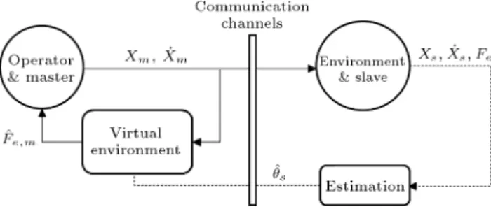
To conquer the deciency mentioned in the pre-vious paragraph, predictive control approaches were introduced in teleoperation systems, primarily by re-searches such as [6] which attempted to exploit online estimated parameters instead of actual transmitted ones. The main advantage of these approaches is that they are able to circumvent the time delay existing in the communication channels, thus making the system more transparent and stable. Various predictive con-trol methods have been proposed in the literature up to now [7], in which the researches have been focused on predicting the environment force on the master side, which is typically called model-mediated teleoperation. In other words, according to this approach, the envi-ronment impedance is estimated on the slave side and, then, transmitted to the master side, where the force is locally recreated based on the position and velocity of the master robot. A general scheme of this approach is depicted in Figure 1.
In spite of providing high transparency, the model-mediated approach creates some new challenges. One of the main challenges is that when the slave robot encounters a new environment, obtaining the true environment impedance may take some time, and also rendering them to the master side is delayed due to the nature of the communication channels. During this period, the master side is not aware of the true en-vironment parameters; thus, the local force cannot be created correctly. This time interval, which is called the period of model mismatch, puts the system in an unsta-ble situation which needs to be suitably controlled [8]. Stability of model-mediated teleoperation has been addressed by some researches in recent years. Some of the proposed approaches provide stability at the expense of transparency, such as [9], which proposes the idea of displacement of the local virtual
Figure 1. General scheme of model-mediated teleoperation approach. x, Fe, and ^Fe;mrepresent
position, environment force, and estimated environment force, respectively. ^s is also the estimated environment
parameters. Subscripts m and s denote master and slave, respectively.
environment in the direction of the movement of the master robot to stabilize the system when the rst contact on the slave side occurs. Passivity-based model updating is another technique which is adopted in [10] by inducing an additional damping factor in the virtual environment when a change in model happens. This may also lead to a decrease in transparency depending on the type of model update. The other proposed approaches, however, have reached the ultimate goal of stabilizing the system through the assumption of a simple environment model [11,12]. As a consequence, presenting a control method that can conserve system stability and transparency together, regardless of the environment type, seems necessary.
In this paper, a control strategy for the period of model mismatch (or equivalently transition state) is incorporated so that the system stability can be preserved even for large amounts of time delay. The strategy is based on the idea of full decoupling whereby master and slave sides are decoupled when a new environment appears. In that period, no signal is transmitted between master and slave sides, and both sides are separately controlled by their own controllers. These controllers are also independent of environment type; therefore, the system is able to interact with both hard and soft environments.
The rest of this paper is organized as follows. Section 2 describes the dynamic modeling of the sys-tem. Section 3 is dedicated to explaining the estimation algorithms used to estimate the impedance for both hard and soft environments. Section 4 describes the controllers designed for the dierent states of the sys-tem and presents discussion on the overall stability of the system. Finally, Section 5 provides the simulation results, while conclusions and suggestions for future researches are included in Section 6.
2. System modeling 2.1. Master side modeling
The dynamics of the master robot is considered as a one-degree-of-freedom, linear second-order system in time domain, as shown in Eq. (1):
mmxm+ bm_xm+ kmxm= Fh+ Um; (1)
where m, b, and k denote the mass, damping coecient, and stiness, respectively. F
h is the interaction force
between the operator and the master robot, and U is the control input. x represents the position of the robot, and subscript m denotes the master robot.
For simulation purposes, it is necessary to obtain a model for human or operator hand. Several models have been proposed for representing the dynamic be-havior of human hand during interaction with teleoper-ation systems. The rst and possibly most well-known
model is the linear second-order one proposed in [13]. However, the authors of [14] proved that a suitable model should be of relative order one. Hence, they derived a two-parameter model based on experimental data that can be written as follows:
ba_xm+ kaxm= Fh Fh; (2)
where ba and ka represent the damping and stiness
coecients of hand, respectively, and Fh is the human
exogenous force. It should be pointed out that, in Eq. (2), it is assumed that the operator continuously and completely grasps the end eector of the master robot, such that the position of his/her hand is always equal to the position of the robot.
By combining Eqs. (1) and (2), the dynamics of the master side can be obtained, which is given by:
mmxm+ bt;m_xm+ kt;mxm= Fh+ Um; (3)
where bt;m= b m+ ba and kt;m, km+ kaare assumed.
2.2. Slave side modeling
The dynamics of the slave robot is considered as a one-degree-of-freedom, linear second-order system in time domain, as indicated in Eq. (4):
msxs+ bs_xs+ ksxs= Us Fe; (4)
where m, b, and k denote the mass, damping coecient, and stiness, respectively; Fe is the environment force
and U is the control input; x species the position of the robot; and subscript s denotes the slave robot.
The environment force can be represented by the augmented Kelvin-Voigt (KV) model for hard environ-ments and the augmented Hunt-Crossley (HC) model for soft environments, which are given by Eqs. (5) and (6), respectively:
Fe=
8 > < > :
KKVxs+ BKV_xs; xs> 0 ^ _xs 0
KKVxs; xs 0 ^ _xs< 0
0; else:
(5)
Fe=
8 > < > :
KHCxsn+ BHCxsn_xs; xs 0 ^ _xs 0
KHCxsn; xs 0 ^ _xs< 0
0; else: (6)
In Eqs. (5) and (6), K and B denote stiness and damping coecients, n is a constant, and xs
represents the environment compression.
The selection of the proper model between KV and HC for the environment is carried out by the hybrid object modeling approach, which is proposed in [15] and augmented in [16]. This approach is represented by operator S as follows:
S(KKV; t) =
(
KV, KKV Kth_ t tth
HC, else; (7)
where Kth and tth are stiness and time thresholds,
respectively, and t is dened as follows:
t= t t w; (8)
where tw species the time of the rst interaction
between the slave robot and the environment. 3. Estimation of environment parameters As mentioned in Section 1, in model-mediated teleop-eration, the environment is virtually created on the master side. Therefore, a particular approach should be adopted for this purpose from dierent methods proposed in the literature. Relevant approaches can be divided into two main categories of model-based and model-free. An example of a model-free approach is [17] in which the environment force is predicted by a neural network on the slave side and is reproduced on the master side. However, our approach in this paper is model-based. Thus, an algorithm rst estimates the environment parameters (KKV and BKV for KV and
KHC; BHC and n for HC) on the slave side, and then
the estimated parameters are sent to the master side in order to create the virtual environment.
Several methods exist for determining the param-eters of a system. There are numerical approaches, such as [18], which are mainly proposed to identify parameters of relatively complicated mechanical sys-tems. Nonetheless, based on the dynamics of the environments dened by Eqs. (5) and (6), a simpler algorithm can be employed for the sake of parameter estimation in this paper. Hence, the SPRLS [19], which is a simple, yet powerful, recursive algorithm, seems a suitable choice. According to this algorithm, the actual and estimated systems should be linearized in the following form:
y = T; (9)
^y = ^T; (10)
where y and ^y are the actual and estimated outputs, and and ^ are actual and estimated parameters, respectively, and is the vector of inputs.
If the estimation error is dened as ^e= y ^y, then vector ^ can be obtained from the following recursive relations:
Li= Pi 1i(1 + iTPi 1i) 1; (11a)
Pi= (I LiTi )Pi 1+ NINT (^e2i 1)I; (11b)
^i= ^i 1+ Li(yi Ti ^i 1); (11c)
where and are constants, I is the identity matrix, and i = 1; 2; ; NINT (:) operator is also dened as follows:
NINT (x)= (
x; x 0:5
0; 0 x < 0:5 : (12)
The next step is to adapt Eqs. (9) and (10) to the KV and HC models. For KV, this can be done conveniently due to its inherent linearity; therefore, we have:
yKV= Fe; (13a)
KV=x _xT; (13b)
KV=KKV BKVT: (13c)
However, adaptation to HC model is not attained as easily as KV. In [20] and [21], double-stage and single-stage methods are proposed, respectively, in order to identify linearized HC parameters to be used in the form of Eqs. (9) and (10). However, Schindeler and Hashtrudi-Zaad utilized a novel and robust procedure for linearizing the HC model [22]. In this method, which is called polynomial linearization, the term xn s
in the HC model is expanded based on Taylor series around its center point of working space, thus yielding the following:
(x)n
0+ 1x + 2(x)2; (14)
where 0, 1, and 2 are coecients that are
ob-tained by arranging the Taylor expansion according to Eq. (14). Now, the HC model can be rewritten as follows:
Fe=
8 > > > < > > > :
KHC(1xs+2(xs)2)+BHC(1xs+2(xs)2) _xs;
xs 0 ^ _xs 0
KHC(1xs+2(xs)2); xs 0 ^ _xs< 0
0; else (15)
where 0= 0 is assumed. Consequently, the linearized
relations for the HC model are obtained as in Eq. (16).
yHC= Fe; (16a)
HC =
h
(x)2 x (x)2_x (x) _xiT; (16b)
HC= [KHC2 KHC1 BHC2 BHC1]T: (16c)
4. Control approach and stability analysis 4.1. Controller design for steady state
The term steady state is adopted from [8] which implies the time when the slave robot is not experiencing new contact with an environment. In other words, the slave robot either is in free motion or has previously encountered a new environment and is now just main-taining the contact. In this situation, regular control
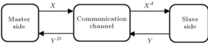
Figure 2. A scheme of the communication channel in the proposed teleoperation system. X and Y represent two arbitrary parameters.
approaches suce. Although any suitably designed controller can be used, in this paper, impedance control and sliding mode control are implemented for the master and slave sides, respectively. Impedance control has the property of rendering the desired impedance on the master side, while the slave is able to track asymptotically the position of the master robot with a sliding mode controller.
Before continuing with design of controllers, it should be noticed that, in this paper, the delayed sig-nals between the master and slave sides are designated by superscripts d and D, as illustrated in Figure 2 and by the following relations:
X(t m)= Xd(t); (17)
Y (t s)= Y D(t); (18)
where m and s are communication time delays from
master to slave side and slave to master side, respec-tively, and X and Y are two arbitrary parameters.
For impedance control of master side, a reference impedance behavior should be rst dened [23,24]. Therefore, we have:
M xm+ B _xm+ Kxm= Fh F^e;m; (19)
where Fhis the human or operator force and:
^ Fe;m=
( ^D
s;KVTm;KV; S(KKV; t) = KV
^D
s;HCTm;HC; S(KKV; t) = HC (20)
where subscripts m and s imply that the parameter should be inserted in or calculated on master and slave sides, respectively. M, B, and K are the reference mass, damping coecient, and stiness, respectively. In addition, ^F(e;m) represents the locally recreated
environment force on the master side.
The term m;HC in Eq. (20) includes the term
xm, as can be regarded in Eq. (16b), which should be
obtained from Eq. (21):
xm= x m xDw; (21)
where xwis the virtual environment position calculated
on the slave side (see Section 4.2).
Finally, by combining Eqs. (3) and (19), the control input for the master side is attained:
Um;st=
bt;m mMmB
_xm+mMm 1
Fh
mm
M F^e;m+
kt;m mMmK
xm; (22)
where subscript st refers to the steady state.
For sliding mode control of the slave side, the error should be dened rst. Here, the denition est= x s
xd
m is used [25]. Then, the sliding surface is obtained
in the following form:
sst(x; t)= _e st+ stest; (23)
where st is strictly positive. Ultimately, the slave
control signal can be derived by implementing the approach explained in the appendix:
Us;st=^bs_xs+ ^ksxs+ ^Fe
+ ^ms
xd
m kgainstsat
sst
'st
st_est
; (24) where ' is boundary layer width for reducing the chat-tering phenomenon, sat(.) is the saturation function, and the accent ^ refers to the uncertain value of the corresponding parameter.
Explanation of parameter kgainst can be found in the appendix. Furthermore, if one cannot or do not desire to use xd
min Eq. (24) directly, he/she can replace
it with the following relation, which is the delayed rearranged form of Eq. (19):
xd
m= M1 (Fhd F^e;md B _xdm Kxdm): (25)
4.2. Locating virtual environment on the master side
In teleoperation systems, which are designed, based on model-mediated approach, locating the virtual environ-ment on the correct position on the master side can greatly inuence the transparency of the system. In fact, if the virtual environment is wrongly placed, xm
in Eq. (21) and, subsequently, vector m in Eq. (20)
will deviate from their real value; thus, the calculated force on the master side will not follow the actual force on the slave side.
Until now, dierent researches have been con-ducted in line with this aim. One of the rst approaches is based on [26], assuming the position of the virtual environment as one of the environment parameters (as in Eqs. 13(c) and 16(c)) and estimating it by an estimation algorithm. This approach requires the environment model to be as simple as possible, which is not always the case. More recent researches have also proposed the use of additional sensors, such as vision or proximity sensors, on the salve side for prior detection of the environment, such as the work done in [9].
However, the authors have previously proposed a
method that is able to dene the location of the virtual environment and the time of collision with environment on the slave side. This method, which is expressed in the following form, leads to the maximum possible transparency [16]:
Xw;j=
8 > < > :
[xs;j 1 tj 1]T; jFe;jj > Fth^ jFe;j 1j Fth
Xw;j 1; jFe;jj > Fth^ jFe;j 1j > Fth
[ tj]T; else (26)
where Xw= [x w tw]T (where twis the time of the rst
interaction with the actual environment), subscripts j and j 1 are the current and past time steps (j = 1; 2; ), respectively, Fth is a force threshold, and
is constant which is selected out of the working space of the robots. In this paper, Fth= 0 is considered.
Even though this method works well for relatively soft environments, it leads to model jump in interac-tion with hard environments [16]. Model jump is a phenomenon that produces a relatively high amount of force in the system in a limited time, thereby making the initial moments of the interaction hazardous for a teleoperation system.
Researches, such as [9], have previously consid-ered reducing the eect of the model jump in the system. However, the main challenge still exists; gen-erally, model jump and system transparency adversely aect each other. Therefore, if we aim to decrease the model jump phenomenon to the most possible extent, a separate control approach should be provided to the initial moment of contact with a new environment, which is discussed in the following section.
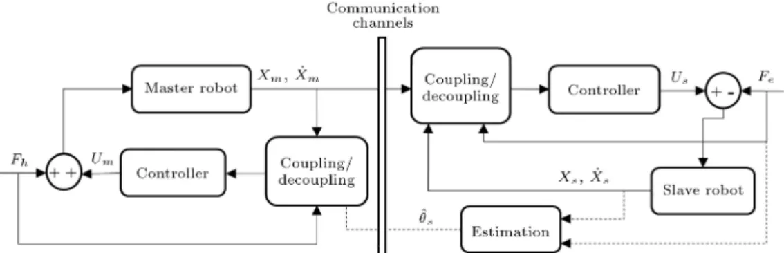
4.3. Controller design for transition state The term transition state is adopted from [8] that implies the initial time of interaction with a new environment. In this situation, as mentioned before, the system may experience large contact forces, which may be extremely detrimental to it. This is generally called model jump eect. To prevent the system from being inuenced by this eect, a novel control approach is proposed to transition state in this section, which is based mainly upon decoupling master and slave sides. Mitra and Niemeyer proposed a technique in [27] whereby the virtual environment is gradually moved toward the correct position using a sliding surface (such as Eq. (23)) when the rst contact with environment occurs. In this approach, however, the master main controller is still active during transition state, which results in degradation of transparency. To compensate for this, master and slave sides need to be fully decoupled during transition state. This means that the controller, which is active during steady state, should be deactivated during transition state.
To the authors' knowledge, the idea of decoupling was rst implemented on a teleoperation system by
Figure 3. General scheme of the decoupling method. The coupling/decoupling blocks choose the input signals to be presented to the controller. Signals passing through the communication channels are only used when the coupling mode is active. Thus, if the decoupling mode is activated, the two control loops are closed separately and locally. x, U, Fe, Fh, and
^s represent position, control signal, environment force, human force, and estimated environment parameters, respectively.
Subscripts m and s denote master and slave, respectively.
Smisek et al. [11]. However, the control strategy adopted there was dierent, and also only relatively sti environments with the elastic model were con-sidered, i.e., Fe = Kxs. This paper extended this
approach to a general case, which is independent of the environment model, guaranteeing system stability during transition state while maintaining high system transparency. A general scheme of the decoupling method is depicted in Figure 3.
Before designing controllers, a precise denition for transition state is presented. Transition state starts from the initial moment of interaction with a new environment and nishes at the time when both sides have become stable or, in other words, have returned to their initial contact positions.
For controlling the system during transition state, sliding mode control is utilized for both master and slave sides. Firstly, the error and sliding surface should be dened. In Eq. (23), the error was considered such that slave robot tracked the delayed position of the master robot, whereas, herein, the error must be dened with the aim of reaching the location of the initial contact. Hence, the error denitions for master and slave sides are presented as follows:
es;tr= x s xw; (27)
em;tr= x m xDw; (28)
where subscript tr denotes the transition state, and subscripts m and s denote master and slave sides, respectively.
Secondly, the sliding surfaces are dened as fol-lows:
ss;tr(x; t)= _e s;tr+ s;tres;tr; (29)
sm;tr(x; t)= _e m;tr+ m;trem;tr: (30)
Finally, similar to the procedure for Eq. (24), the control signals for both sides in transition state can be achieved as mentioned in the appendix:
Us;tr=^bs_xs+ ^ksxs+ ^Fe
+ ^ms( kgains;trsat
ss;tr
's;tr
s;tr_es;tr); (31)
Um;tr=^bt;m_xm+ ^kt;mxm F^e;m
+ ^mm( kgainm;trsat
sm;tr
'm;tr
m;tr_em;tr):
(32) Note that xw and xDw are constants by denition (as
dened in Eq. (26)). Thus, taking the derivatives of the dened errors in Eqs. (27) and (28), we can easily conclude that _es;tr= _xs and _em;tr= _xm.
Obviously, Eqs. (31) and (32) do not contain any of the environment parameters. Therefore, this control strategy can be incorporated in a teleoperation system that deals with not only the environments dened by Eqs. (5) and (6) (which can be indeed a good approximation for most environments), but also any other environment with dierent dynamics.
The important point which is considered in tran-sition state is that the operator exerts no force during this period [11]. In other words, when the operator notices the rst signal of collision between the slave robot and the environment, he/she ceases pushing the master robot forward while still completely grasping it. When the transition state has nished, the operator reinitializes the operation.
4.4. Discussion of system stability
Overall stability of a teleoperation system should be discussed through two aspects. One aspect concerns the stability of the controllers designed on master and slave sides, and the other is the stability of the
communication channels. In this paper, the former aspect is fullled readily due to utilizing impedance and sliding mode controllers, which are well known to be stable if tuned suitably. The latter, however, requires a deeper analysis, since it deals with the delayed signals that are transmitted through communication channels.
Considering classical control architectures de-scribed in Section 1, generally, two well-known ap-proaches are employed to analyze the stability of the communication channels in a teleoperation system, though other approaches exist, too. The rst one is absolute stability, for which the necessary and sucient conditions are provided by Llewellyn's stability crite-rion [28]. An example of a design based on absolute stability can be found in [3]. The second one is passivity, which is adopted to analyze the stability of the system from energy generation point of view. An example of a passivity-based design can be found in [29]. These methods, however, make eorts to stabilize a teleoperation system basically when merely delayed signals are available on each side of it, which is not the case when it comes to model-mediated teleoperation.
As explained before, in model-mediated teleop-eration, the master side is in interaction with a lo-cal virtual environment instead of the delayed force signal from the slave side. Accordingly, the master control loop is closed locally and, considering passive human operator and environment, the system is always stable (the master local loop could be inferred from Figure 1, too). The only remaining stability issues are thus as follows. First, the estimation algorithm must be convergent, which is attained in this paper by using the SPRLS algorithm. Second, the tran-sition state must be controlled so that it does not destabilize the system, which is addressed in this paper.
Finally, it should be noted that the aforemen-tioned analysis pertains to the slave-to-master direc-tion of the teleoperadirec-tion system applied in this work. The stability analysis regarding the master-to-slave direction is analogous to that in the previous works in this eld, e.g. [30]. In addition, note that some researches, such as [10], have recently extended the concept of passivity to the context of model-mediated teleoperation. Despite having the same name and overall concept, these works should be separated from the conventional passivity analysis mentioned in the beginning of this section due to the dierence in their control architectures.
5. Simulation results
To study the validity of the proposed approach, simula-tion results are presented for the designed teleoperasimula-tion
system in this section.
For simulating human operator force, the follow-ing function is considered
Fh=
8 > > > > > > < > > > > > > :
2t; 0 t < 2
4; 2 t < T ^ t 2 steady state 0; 2 t < T ^ t 2 transition state
1
7(t 6) + 4; T t < 13 5
2(t 15); 13 t 15;
(33)
where T is the time when the transition state nishes and can be tuned based on the operation circum-stances. Herein, we determined T = 6 s by trial and error. In addition, when Fh is zero, it indicates that
the human operator has stopped pushing forward the master robot and is waiting for the system to reach a stable point. Note that, in Eq. (33), t is in seconds.
A time delay of 0.5 s for both communication channels is considered (equivalent to a round-trip time delay of 1 s), which means that m = s = 0:5 s. In
addition, an uncertainty interval is assumed for the mass of the slave robot as follows:
1:058 kg ms 1:267 kg: (34)
Furthermore, in order to validate the generality of the proposed approach, two sample hard and soft environments are considered for interaction with the slave robot. Although hard and soft are intrinsically qualitative terms, it is common in the literature to assume an environment with stiness bigger than 2500 N/m (i.e., K > 2500 N/m) as hard and, other-wise, as soft [15,20]. For damping coecient, however, such a general convention does not exist; however, it seems a good estimation to consider the ratio K
B 30
s 1[15]. It is also a suitable approximation to consider
1 < n < 2 for exponent n [20,22]. The properties of the simulated environments, in addition to other assumptions, for the system are mentioned in Tables 1 to 6. The tuning of the sliding mode controllers (Tables
Table 1. Dynamical properties of the master and slave robots (Phantom Omni for master and Novint Falcon for slave) [24].
Parameter Value Unit
mm 0.223 kg
bm 17.227 Ns/m
km 6.286 N/m
M 0.223 kg
B 20.827 Ns/m
K 40.286 N/m
ms 1.158 kg
bs 115.40 Ns/m
Table 2. Dynamical properties of the human hand [14]. Parameter Value Unit
ba 3.6 Ns/m
ka 40 N/m
Table 3. Parameters of sliding mode controller for steady state.
Parameter Value
st 15
st 1
'st 0.1
Kgainst 1:1Kgain;minst
Table 4. Parameters of sliding mode controllers for transition state.
Parameter Value
s;tr 15
s;tr 1
's;tr 0.3
Kgains;tr 1.1 Kgain,mins;tr
m;tr 15
m;tr 1
'm;tr 0.3
Kgainm;tr 1.1 Kgain,minm;tr
Table 5. Parameters of the hard environment, the corresponding SPRLS algorithm, and the hybrid object modeling approach.
Parameter Value Unit
KKV 6000 N/m
BKV 230 Ns/m
0.1 {
30000 {
^
0 [3000 100]T {
P0 I2a {
^e0 3 {
SPRLS sample time 0.0005 s
Kth 2500 N/m
tth 0.1 s
a I is the identity matrix.
Table 6. Parameters of the soft environment, the corresponding SPRLS algorithm, and the hybrid object modeling approach.
Parameter Value Unit
KHC 1000 N/m
BHC 30 Ns/m
n 1.5 {
19000 {
1 {
^
0 [400 400 13 13]T {
P0 I4a {
^e0 2 {
SPRLS sample time 0.0005 s
Kth 2500 N/m
tth 0.1 s
a I is the identity matrix.
3 and 4) and the parameters of the SPRLS algorithm (Tables 5 and 6) was conducted manually.
The results of the simulation are also illustrated in Figures 4 to 11. From Figures 4 and 8, it can be seen that when a new environment is encountered, whether hard or soft, the transition state starts and continues until both master and slave sides become
Figure 4. Environment and master reaction forces in interaction with the hard environment. The black dashed lines represent the start and end of the transition state.
Figure 5. Master and slave positions in interaction with the hard environment. The black dashed line (vertical) represents the end of the transition state (the transient state starts when the slave reaches the environment for the rst time). The green dashed line (horizontal) shows the position of the environment on the slave side.
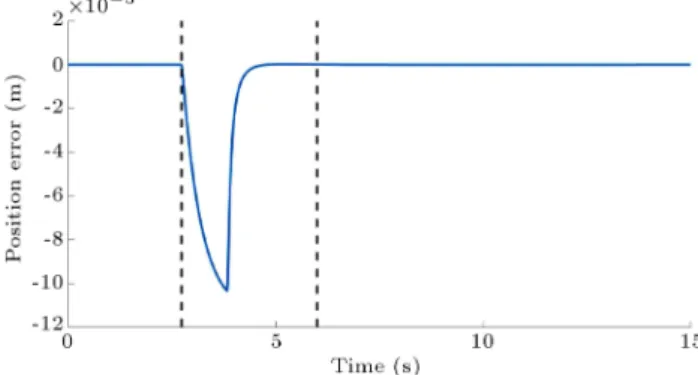
Figure 6. Position error in interaction with the hard environment. The black dashed lines represent the start and end of the transition state. Although otherwise dened in Section 4.3, the error depicted for the transition state is based on the denition in Section 4.1.
Figure 7. Slave control input in interaction with the hard environment.
Figure 8. Environment and master reaction forces in interaction with the soft environment. The black dashed lines represent the start and end of the transition state.
Figure 9. Master and slave positions in interaction with the soft environment. The black dashed line (vertical) represents the end of the transition state (the transient state starts when the slave reaches the environment for the rst time). The green dashed line (horizontal) shows the position of the environment on the slave side.
stable. After that, the system goes to the steady state again while normal operation is being carried out. Two important points can be inferred from these two gures: Firstly, the master robot is able to track the environment force ahead accurately, due to the predictive architecture used, during the steady state (which shows high transparency); secondly, the model jump eect has been drastically decreased, especially if compared with the results presented in [16] (showing increased stability).
Figure 10. Position error in interaction with the soft environment. The black dashed lines represent the start and end of the transition state. Although otherwise dened in Section 4.3, the error depicted for the transition state is based on the denition in Section 4.1.
Figure 11. Slave control input in interaction with the soft environment.
Figures 5 and 9 show that, for both hard and soft environments, the slave robot tracks the position of the master robot behind (due to the inherent time delay in the communication channels). In Figures 6 and 10, the position error between the master and slave robots is depicted that further proves the quality of the position tacking of the system for both hard and soft contacts and during free motion (no contact with environment). Finally, the control input of the slave robot is illustrated in Figures 7 and 11 during contact with hard and soft environments, respectively. It should be pointed out that the master control input is equal to the master reaction force (in magnitude) as shown in Figures 4 and 8. Moreover, note that transparency cannot be considered for transition state due to its nature. To put it simply, transparency can be dened when signals are being transmitted between two sides of a teleoperation system, while no signal is transmitted during transition state by denition.
Despite high transparency, it can be observed that, after the end of the transition state during interaction with the soft environment (Figure 8), trans-parency is not as high as that when it is in interaction with the hard environment for some time. The reason is that the system has not yet decided which model,
i.e., KV or HC, to use for the virtual environment. Considering hybrid object modeling approach dened by Eq. (7), it can be concluded that when encountering a soft environment, the system needs a particular amount of time to change the default model of virtual environment (from KV to HC) on the master side. Considering the time delays in the communication channels, the system carries out this task in approx-imately m+ s+ tthseconds. This eect is inevitable
during the rst interaction with a completely unknown environment. However, in subsequent contacts, this phenomenon can be avoided by reproducing the rst contact's data if the environment is known to remain unchanged during the operation.
Another issue that may arise when utilizing the proposed full decoupling method is the time when the operator is required to wait until the system becomes stable during the transition state. The user might conceive of this waiting duration as a distracting factor. This interval, however, could be adjusted based on the desired application by suitably tuning the sliding mode controller parameters, although it cannot be completely omitted.
6. Conclusions and future work
In this paper, the idea of decoupling master and slave sides in a teleoperation system during a new contact with an environment for decreasing the model jump eect was addressed. A novel position control approach based on sliding mode control was proposed for transition state, while the master and slave sides were fully decoupled. The principal advantage of the proposed approach, in comparison with previous works, is its independence of environment model. This means that, regardless of environment type and system dynamics, the proposed control approach leads the system towards stability when it rst encounters a new unknown environment, while high transparency is preserved.
In addition, this approach is capable of dealing with any nite time delay in communication channels. Thus, with suitable tuning of dierent parameters of controllers, the stability of teleoperation system is guaranteed in the presence of large amounts of time delay.
Despite guaranteed stability and high trans-parency, the waiting time interval during transition state, in which the operator must stop the operation until the system reaches stability, can be of incon-venience for the user. Nevertheless, suitably tuning the relevant sliding mode controller parameters can partly compensate for this issue. Interaction with an unknown soft environment for the rst time may also provide an inconvenient condition for the user, as thoroughly discussed in Section 5. These two sources
of inconvenience are to be further investigated through experimental tests in future works. How and how much these two sources can aect the haptic feeling of the user and how to mitigate them, if necessary, can be discussed.
Moreover, this paper used the predictive control approach merely for slave-to-master direction. In order to further augment the transparency and stability of the system, master-to-slave state prediction can also be taken into account in the presence of environment force in future works.
References
1. Aliaga, I., Rubio, A., and Sanchez, E. \Experimental quantitative comparison of dierent control architec-tures for master-slave teleoperation", IEEE Transac-tions on Control Systems Technology, 12(1), pp. 2-11 (2004).
2. Hua, C.-C., Yang, Y., and Guan, X. \Neural network-based adaptive position tracking control for bilateral teleoperation under constant time delay", Neurocom-puting, 113, pp. 204-212 (2013).
3. Garca-Valdovinos, L.-G., Parra-Vega, V., and Arteaga, M.A. \Observer-based sliding mode impedance control of bilateral teleoperation under constant unknown time delay", Robotics and Autonomous Systems, 55(8), pp. 609-617 (2007). 4. Cho, H.C. and Park, J.H. \Impedance control with
variable damping for bilateral teleoperation under time delay", JSME International Journal Series C Mechan-ical Systems, Machine Elements and Manufacturing, 48(4), pp. 695-703 (2005).
5. Weber, C., Nitsch, V., Unterhinninghofen, U., Farber, B., and Buss, M. \Position and force augmentation in a telepresence system and their eects on perceived re-alism", Third Joint Eurohaptics Conference and Sym-posium on Haptic Interfaces for Virtual Environment and Teleoperator Systems, Salt Lake City, UT, USA, pp. 226-231 (2009).
6. Hannaford, B. \A design framework for teleoperators with kinesthetic feedback", IEEE Transactions on Robotics and Automation, 5(4), pp. 426-434 (1989). 7. Uddin, R. and Ryu, J. \Predictive control approaches
for bilateral teleoperation", Annual Reviews in Con-trol, 42, pp. 82-99 (2016).
8. Xu, X., Cizmeci, B., Schuwerk, C., and Steinbach, E. \Model-mediated teleoperation: Toward stable and transparent teleoperation systems", IEEE Access, 4, pp. 425-449 (2016).
9. Xu, X., Paggetti, G., and Steinbach, E. \Dynamic model displacement for model-mediated teleopera-tion", IEEE World Haptics Conference (WHC), Dae-jeon, Korea, pp. 313-318 (2013).
10. Xu, X., Schuwerk, C., and Steinbach, E. \Passivity-based model updating for Model-mediated Teleopera-tion", IEEE International Conference on Multimedia
& Expo Workshops (ICMEW), Turin, Italy, pp. 1-6 (2015).
11. Smisek, J., van Paassen, R.M., and Schiele, A. \Naturally-transitioning rate-to-force controller robust to time delay by model-mediated teleoperation", IEEE International Conference on Systems, Man, and Cy-bernetics (SMC), Hong Kong, pp. 3066-3071 (2015). 12. Willaert, B., Van Brussel, H., and Niemeyer, G.
\Stability of model-mediated teleoperation: discus-sion and experiments", International Conference on Human Haptic Sensing and Touch Enabled Computer Applications, Tampere, Finland, pp. 625-636 (2012). 13. Lawrence, D.A. \Stability and transparency in
bilat-eral teleoperation", IEEE Transactions on Robotics and Automation, 9(5), pp. 624-637 (1993).
14. Speich, J.E., Shao, L., and Goldfarb, M. \Modeling the human hand as it interacts with a telemanipulation system", Mechatronics, 15(9), pp. 1127-1142 (2005). 15. Achhammer, A., Weber, C., Peer, A., and Buss,
M. \Improvement of model-mediated teleoperation us-ing a new hybrid environment estimation technique", IEEE International Conference on Robotics and Au-tomation (ICRA), Anchorage, Alaska, USA, pp. 5358-5363 (2010).
16. Yazdankhoo, B. and Beigzadeh, B. \Improving trans-parency in bilateral teleoperation systems based on model-mediated approach", Modares Mechanical En-gineering, 17(1), pp. 273-283 (2017) (in Persian). 17. Smith, A.C. and Hashtrudi-Zaad, K. \Neural
network-based teleoperation using Smith predictors", IEEE In-ternational Conference Mechatronics and Automation, Niagara Falls, Canada, 3, pp. 1654-1659 (2005). 18. Tarvirdizadeh, B., Khanmirza, E., Ebrahimi, M.,
Kalhor, A., and Vakilipour, S. \An ecient numerical and experimental system identication approach for a exible manipulator", Engineering Computations, 32(8), pp. 2467-2490 (2015).
19. Park, D.-J. and Jun, B.-E. \Selfperturbing recursive least squares algorithm with fast tracking capability", Electronics Letters, 28(6), pp. 558-559 (1992). 20. Diolaiti, N., Melchiorri, C., and Stramigioli, S.
\Con-tact impedance estimation for robotic systems", IEEE Transactions on Robotics, 21(5), pp. 925-935 (2005). 21. Haddadi, A. and Hashtrudi-Zaad, K. \Real-time
iden-tication of Hunt-Crossley dynamic models of contact environments", IEEE Transactions on robotics, 28(3), pp. 555-566 (2012).
22. Schindeler, R. and Hashtrudi-Zaad, K. \Polynomial linearization for real-time identication of environment Hunt-Crossley models", IEEE Haptics Symposium (HAPTICS), Pennsylvania, USA, pp. 173-178 (2016). 23. Sadeghi, M.S., Momeni, H.R., and Amirifar, R. \h1
and 11 control of a teleoperation system via LMIs", Applied Mathematics and Computation, 206(2), pp. 669-677 (2008).
24. Hilliard, T. and Pan, Y.-J. \Stabilization of asymmet-ric bilateral teleoperation systems for haptic devices with time-varying delays", American Control Confer-ence, Washington, DC, USA, pp. 4538-4543 (2013). 25. Park, J.H. and Cho, H.C. \Sliding mode control of
bilateral teleoperation systems with force-reection on the internet", IEEE/RSJ International Conference on Intelligent Robots and Systems (IROS), Takamatsu, Japan, 2 pp. 1187-1192 (2000).
26. Tzafestas, C., Velanas, S., and Fakiridis, G. \Adaptive impedance control in haptic teleoperation to improve transparency under time-delay", IEEE International Conference on Robotics and Automation (ICRA), Pasadena, CA, USA, pp. 212-219 (2008).
27. Mitra, P. and Niemeyer, G. \Model-mediated tele-manipulation", The International Journal of Robotics Research, 27(2), pp. 253-262 (2008).
28. Llewellyn, F. \Some fundamental properties of trans-mission systems", Proceedings of the IRE, 40(3), pp. 271-283 (1952).
29. Lee, D. and Spong, M.W. \Passive bilateral teleopera-tion with constant time delay", IEEE Transacteleopera-tions on Robotics, 22(2), pp. 269-281 (2006).
30. Cho, H.C., Park, J.H., Kim, K., and Park, J.-O. \Sliding-mode-based impedance controller for bilat-eral teleoperation under varying time-delay", IEEE International Conference on Robotics and Automation (ICRA), Seoul, Korea, 1 pp. 1025-1030 (2001).
Appendix
The procedure for determining the control input of the sliding mode control for the slave side in steady state is explained here. First, Eq. (4) is rewritten in the following form:
xs= f(xxxsss; t) + g(xxxsss; t)Us;st; (A.1)
where xxxsss= [xs _xs]T is the state vector. In addition,
f , f(xxxsss; t) and g , g(xxxsss; t) can be obtained as follows:
f = m1
s( bs_xs ksxs Fe); (A.2)
g = 1
ms: (A.3)
Herein, f and g can have uncertainties, but in known ranges which are dened as follows:
^f f F; (A.4)
1
g
^g ; (A.5)
where ^f and ^g represent the estimated values of f and g, respectively. In Eq. (A.5), ^g and are dened according to the following relations:
^g=pgmaxgmin; (A.6)
= rg
max
gmin; (A.7)
where subscripts max and min denote the maximum and minimum values of the corresponding parameter, respectively. Next, by having the sliding surface as dened in Eq. (23) and applying the condition sst =
_sst = 0, the estimated control input is dened as
follows: ^
Us;st= 1^g^u; (A.8)
where,
^u= ^ f + xd
m st_est: (A.9)
Finally, the sliding condition must be applied according to Eq. (A.10):
sst_sst stjsstj ; (A.10)
where st is strictly positive. It can be shown that a
control input in the following form satises Condition in Eq. (A.10):
Us;st= ^Us;st 1^gkgainstsat( sst
'st): (A.11)
In Eq. (A.11), kgainst is dened such that:
kgainst kgain;minst; (A.12) kgain;minst
= (F + st) + ( 1) j^uj : (A.13)
Other parameters in Eq. (A.11) have been dened in Section 4.1. Ultimately, by rewriting Eq. (A.11) according to Eqs. (A.2), (A.3), (A.8), and (A.9), the control input can be obtained which is represented by Eq. (24) in Section 4.1.
Notice that the control inputs for transition state (represented by Eqs. (31) and (32) in Section 4.3) can also be achieved through the aforementioned process. The only alterations are that subscript st should be replaced by tr (denoting the transition state) and also subscript s should be replaced by m for obtaining Um;tr.
Biographies
Behnam Yazdankhoo received the BSc degree in Mechanical Engineering from Amirkabir University of Technology, Tehran, Iran in 2015. He is currently MSc student in the School of Mechanical Engineering at Iran University of Science and Technology, Tehran, Iran. His main research interests are design and control of haptic teleoperation systems and humanoid robots. Borhan Beigzadeh received his PhD degree in Me-chanical Engineering from Sharif University of Technol-ogy in 2011, working on dynamic walking systems and studying their correlation with dynamic passive/active manipulation systems. He then joined Iran Univer-sity of Science and Technology (IUST) in Tehran where he established Biomechatronics and Cognitive Engineering Research Laboratory, and since then is an Assistant Professor at the School of Mechanical Engineering. His research interests cover non-linear dynamics and control, robotics, biomechatronics, and cognitive engineering.