ORIGINAL ARTICLE
Solar Support for Natural Ventilation
Sławomir RabczakFaculty of civil and environmental engineering and architecture department of heat engineering and air conditioning, Rzeszów University of Technology, Poland
Abstract:One of the most type of buildings ventilation is a natural ventilation, also called as gravitational ventila-tion. The driving force for natural ventilation comes from the difference in air density. Cold air flows into the rooms through leaks in the windows and walls of the building or through diffusers installed in the windows and walls. Gravitational ventilation systems are the optimal solution because its use only the forces of nature. Unfortunately, it can not always be used. When significant level of air exchange in the room is required, the possibilities of classical air exchange are exceeded (especially in summer). This is a reason, why air flow need forced exchange comes from fan. In summer, the temperature difference between indoor and outdoor air and as well as a difference in density of air columns, does not provide adequate air flow, and can produce an inverse flow in chimney. Systems supporting an air flow by used wind ener-gy does not solve the problem, because it works in the time of maximum ambient temperature (cause of the sun) while the lack of air movement is very often.
Keywords:Natural ventilation; Foil exchanger; Solar support; Heat exchanger
1. Introduction
A popular type of building ventilation is natural ventilation, also called gravitational ventilation. The driving force of natural ventilation is the difference in the density of cold and warm air. Cold air flows into the rooms through leaks in the windows and walls of the building or through air inlets installed in the windows and walls. After mixing with the air in the room and heating, it leaves the room, together with impurities, through the ventilation grilles con-nected to the ventilation ducts[1]. Gravitational ventilation systems are the optimal solution because they use natural forces to operate. Unfortunately, you cannot always use them. When a significant level of air exchange in the room is required, the possibilities of a classic air exchange solution using gravity are exceeded (especially during the summer). For this reason, forced air movement is applied by means of fans. In summer, the temperature difference outside and inside the room, and thus the difference in density of air poles, does not provide adequate air draft and can produce a reverse sequence. String assist systems that use wind energy do not solve the problem, because it is during the maximum heating of the surrounding area that the sun often lacks air movement.
2. Technical solutions of the solar support system for natural ventilation
To support gravitational ventilation, you can use air heating in the gravity channel during the summer. Solar energy can be used for heating gravity ventilation channels with the participation of solar collectors. Collectors are energy devices that absorb the energy of solar radiation and convert it into heat by means of an operating medium that mediates this transformation, most often an aqueous glycol solution. The exhaust air duct can be connected to the solar collector
Copyright © 2018 Sławomir Rabczak doi: 10.18686/utc.v4i2.31
This is an open-access article distributed under the terms of the Creative Commons Attribution Unported License
(http://creativecommons.org/licenses/by-nc/4.0/), which permits unrestricted use, distribution, and reproduction in any medium, provided the original work is properly cited.
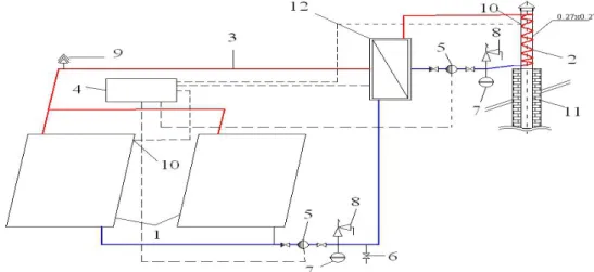
in a suitable housing. The sun, heats the collector and indirectly the stream of air flowing through it, creating a chimney draft[2]. Below are a number of proposals of gravitational ventilation systems supported by solar energy[3,4].Figure 1 presents a solar installation for heating air using a liquid-liquid heat exchanger 12 (desig- nations as in Figure 1). The solar collectors 1 heat the liquid which in the heat exchanger 12 heats the liquid circu-lating in the coil 2 mounted on the extension of the gravity ventilation channel 11 or on the gravity channel. Through the exchanger (coil) 2 installed on the ventilation duct 11, the air inside is heated, and due to the fact that the outside air temperature is lower than the temperature in the ventilation duct, natural ventilation will work properly.
Figure 1.Solar installation diagram of natural ventilation using a heat exchanger.
1- solar collector, 2 – heat exchanger (coil), 3 – pipes, 4 – regulation unit, 5 – circulation pump, 6 –release valve, 7 – expansion vessel, 8 – safety valve, 9 – vent valve, 10 – temperature sensor, 11 – natural ventilation channel, 12 – water-water heat exchanger
The disadvantages are two circuits in which circulating pumps 5 supplied with electric energy are used, as well as two heat exchangers: liquid -tank 12 and (coil) liquid - air 2, on which there are pressure losses necessary to overcome using external electric energy, which increases operating costs of the ventilation system itself. The solar (cylindrical) solar collectors can also be used (Figure 2). The outer sleeve (solar foil collector 1) with diameter D is transparent, lies directly on the ground or roof and serves as the cover - covers against heat loss from the absorber. The role of the absorber is fulfilled by an internal black sleeve with diameter d <D.
The ends of both sleeves of the solar collector 1 are fastened on both sides to cylindrical rollers. The external air flows through the foil solar collector 1 by heating and is guided by the supply line 3 to the shirt 2 surrounding the gravitational ventilation duct 4. Flowing along the ventilation duct 4 transmits heat to the indoor air (room air) by heating it to a temperature higher than the air temperature external: then the so-called chimney draft. In the following solution, there is no need to supply energy from an external source, because the air heated in solar collector 1 flows to the shirt located on the extension of the ventilation duct 4 under the influence of differential pressure[7]. The advantage of the following solution is its virtually maintenance-free operation, there is no need to supply electricity and a low installation cost.
Figure 2.Schema of installation with solar collector foil. 1 – foil solar collector, 2 – air shirt, 3 – heated air channel, 4 – natural ventilation channel
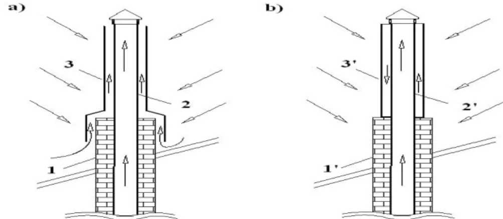
The disadvantage of this solution is the large dimensions of the solar collector 1 needed to obtain the proper air temperature as well as the heat loss generated when heating the air inside the gravity ventilation channel 4. With the use of a suitable solar panel construction, it is possible to use it directly on the gravity ventilation pipe 1 and its extension 2 (Figure 3).
Figure 3.Schema of installation with solar collector foil on existing channel. a) ventilated collector,b) dazzled collector: 1, 1' – natural ventilation channel, 2, 2'– extension ventilation channel, 3 – foil solar collector, 3' – dazzled air solar collector
The installation of the solar collector 3 on the already existing natural ventilation channel 1 will increase its length, and thus extend the air flow path, which will allow it to raise its temperature. The external air flowing along the ventilation duct 1 is heated by the sun's rays. Warm air heats the ventilation duct, and thus the air inside. The advantage of this solution is completely independent work without the need to supply external energy sources, low installation cost, no additional elements makes the system very easy to manufacture and operate.
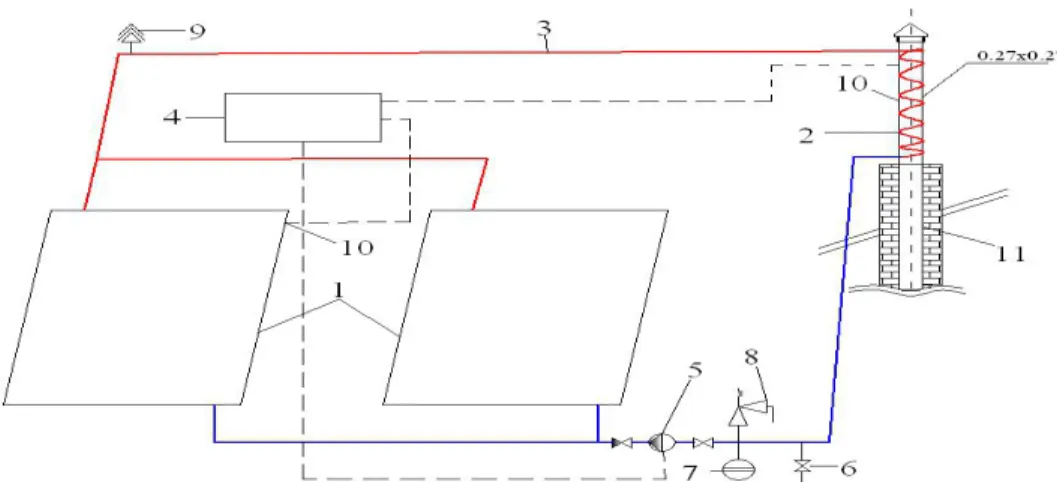
The main disadvantages are the size of the installation as well as the lack of automation that controls the correct operation of the solar collector.Figure 4shows the use of a solar installation for heating air in the ventilation duct 11 by means of a coil 2 through which heated liquid in solar collectors 1 flows.
Figure 4.Schema of solar system to heat the air duct using a coil.
1 – solar collector, 2 – coil (water-air heat exchanger), 3 – pipes, 4 – regulator, 5 – circulation pump, 6 – released valve, 7 – expansion vessel, 8 – safety valve, 9 – vent valve, 10 – temperature sensor, 11 – natural ventilation channel
The regulator 4 in this system is responsible for maintaining the appropriate temperature range of the air in the gravity ventilation duct 11 by changing the water flow rate through the solar collector 1. In this solution a circulating pump 5 may be used to force the flow or a solution may be considered without a circulating pump 5 assuming that the solar collectors 1 are mounted below the coil 2, respectively. The disadvantages include a circuit in which a circulating pump 5 supplied with electric energy as well as a coil (water-air heat exchanger) 2 is used, at which there are temperatures.
Solar collectors 1 can be used in a heating system for hot water heating. and an additional heat exchanger 10 used to heat the gravity ventilation duct (Figure 6). Solar collectors 1 heat priority hot water, and then through a heat exchanger 10, it heat water in coil 3 installed on the extended section of natural ventilation 2.
Figure 6.Schema of solar gravitational ventilation system with solar collector and the additional heat exchanger. 1 – solar collector, 2 – natural ventilation channel, 3 – coil (heat exchanger), 4 – regulator,
5 – circulation pump, 6 – expansion vessel, 7 – safety valve, 8 – vent valve, 9 – temperature sensor, 10 –heat exchanger, 11 – hot water solar tank with coil
The proposed proposal is very beneficial, as heat to support gravitational ventilation is needed only during the summer, and it is precisely during this period that the strongest solar radiation, which often exceeds the need to prepare
hot water. The main disadvantage is the circulation through the coil (heat exchanger) installed on the extension of the gravity ventilation duct 2. It is switched on only when the appropriate temperature range in the hot water tank will be reached.
Another solution (Figure 7) shows the installation using a liquid-air heat exchanger. In solar collectors 1 the liquid is heated, which in the heat exchanger 11 transfers the heat to the air, and the already heated air is guided by a supply line by means of a fan 10 to the gravitational ventilation channel 2 where it is mixed with the internal air raising its temperature. The advantage of this solution is the control system 4, which guarantees the correct operation of the solar installation, thus the proper operation of supporting gravity ventilation. The disadvantages are two circuits in which an electrically powered circulating pump 5 is used, as well as a fan 12 and a water-air heat exchanger 11 on which losses occur. Presented proposals for gravity ventilation systems supported by solar energy are a technical concept showing the extensive possibilities of using renewable energy.
3. Computational analysis of the system
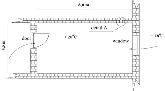
The gravitational ventilation system supported by solar energy[4]was analyzed with the use of liquid collectors and a heat exchanger installed on the ventilation duct extension (Figure 4). By means of solar collectors, the heating medium will be heated, which, through the coils mounted on the gravity ventilation duct, will heat the internal air, which will result in the creation of the thrust. If the outside air has a temperature lower than the internal air temperature, and more precisely, if the temperature in the gravity ventilation ducts is higher than the outside air temperature, then a chimney draft is created, resulting from the difference in external air weights and air in the ducts. The following preliminary calculations of the solar-assisted gravitational ventilation system were made for an office room with dimensions of 8.0 x 4.5 x 3.0 m shown inFigure 8andFigure 9. The cross-section of the ventilation duct was assumed for calculations, F = a x b = 0.27 x 0.27 m (0.0729 m2), ventilation duct height, hk= 5 m, the number of occupied people in the room - 2, outdoor air parameters adopted for Poland[5], i.e.: external temperature tz= 28oC, relative humidity φ = 52%. The temperature of the internal air
tw= 20oC. The average activity in an office room was assumed.
Figure 7.Schema of solar system using a heat exchanger water-air interface.
1 – solar collection, 2 – natural ventilation channel, 3 – pipes, 4 – regulation unit, 5 – circulation pump, 6 – release valve, 7 – expansion vessel, 8 – safety valve, 9 – vent valve, 10 – temperature sensor, 11 – water-air heat exchanger, 12 – fun
People
[W] Lighting[W] Transparentdividers [W]
Sensible heat gain [W]
Non-transparent dividers
[W]
SUM [W]
180 47,8 99 120 60 326,8
Table 1.Summary of heat gains in analyzed room.
The amount of ventilation air for the room under consideration is V = 120 m3/h. It should be noted that the same amount of ventilation air (only for room ventilation, not air conditioning as in this case) in accordance with the technical conditions would be 60 m3/h.
Figure 8.Diagram of room for natural ventilation calculations.
The active pressure Pcz1, which is the result of the difference in weights of the external air and air in the channel will be: Pcz1= hk∙ g ∙ (ρz- ρw) = 5 ∙ 9,81 ∙ (1,175 - 1,2) = - 1,42 Pa, (1)
where: hk- height of the gravity ventilation duct measured from the air inlet to the ventilation grid, and more precisely from the axis of the external air inlet opening, to the outlet from the duct above the roof of the building: hk = 5 m, g - gravitational acceleration: g = 9,81 m/s2,
ρz- external air density for an external temperature of 28oC: ρz= 1,175 kg/m3, ρw- air density in the channel at 20oC: ρw = 1.2 kg/m3.
The result of the calculations indicates emphatically that gravitational ventilation is not working.
Calculation of the Pcz2 pressure caused by local resistances and friction resistance for the diagrams shown in Figure 8and 9 (with gravitational ventilation in optimal conditions, the amount of ventilation air V = 120 m3/h): Pcz2 = (wk2∙ρ/2) ∙ (Σ ξ + λ ∙ hk/Dz) [Pa],(2)
where: wk- air velocity in the gravity ventilation duct calculated according to V = 120 m3/h and F = 0.0729 m2: wk= 0.46 m/s,
Σξ - the sum of local resistance coefficients,
λ - dimensionless coefficient of friction for k = 3 mm: λ = 0.056, Dz- diameter equivalent to a rectangular channel: Dz= 0,27 m.
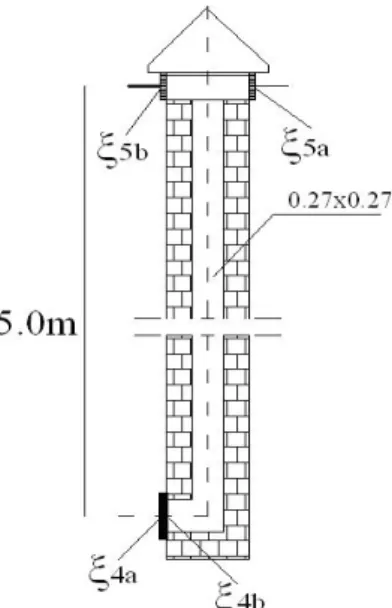
Figure 9.Cross-section through the outlet of the air duct - detail A.
The translation calculation of local resistance coefficients Σ ξ of the air inflow is summarized below. = 5a+ 5b+ 3+ 4a+ 4b= 0,9 + 0,95 + 1,7 + 0,61 + 0,66 = 4,82 [-],(3)
where: 4a– ventilation grille, 4a= 0,9,
4b– outlet from the grill to the room, 4b= 0,95, 3– air flow through the grille in the door, 3=1,7, 5a– inlet to the ventilation grille, 5a= 0,61, 5b– air outlet above the roof, 5b= 0,66.
Hence, the flow resistance is ultimately Pcz2 = 0.75 Pa. In order for gravity ventilation to work properly, the following condition must be met: Pcz1> Pcz2.
The above calculations show that gravity ventilation in the summer period does not work properly. To force its operation, you can extend the length of the natural ventilation channel and heat the air by means of solar energy, for example to a temperature of 40oC. Then, the appropriate active pressure will be created, which will allow the use of gravity ventilation in the summer time without the need for mounting exhaust fans. The air movement will be caused by the difference in temperature, and thus the density between the external air and the gravitational ventilation located in the duct. Figure 10 presents a cross-sectional diagram including the extension of the gravity ventilation duct. Calculations of the active pressure Pcz1 according to the dependence (1) for the conditions shown in Figure 8 and Figure 10(at air temperature in the ventilation duct 40 °C) give the values Pcz1* = 5 m ∙ 9,81 ∙ (1,175 - 1,127)
= 2,354 Pa. Total active pressure in the ventilation duct with extension: Pcz1* = Pcz1+ Pcz1*= 0,934 [Pa](4)
where: Pcz1– active pressure in the channel without extension; Pcz1= -1,42 Pa, Pcz1* – active pressure in canals with extension; Pcz1*= 2,354 Pa.
Figure 10.Cross-section through the outlet channel, taking into account the extension of natural ventilation - detail A. When checking the condition of Pcz1**> Pcz2, 0.934 Pa > 0.75 Pa, it follows that this time, despite the summer period, natural ventilation will work effectively. Fig. 4 presents a schematic diagram of the installation, which, thanks to support with solar collectors and after meeting the conditions of the above calculations, will allow correct operation of gravity ventilation in the summer time period. The thermal power necessary to heat the air in the gravitational ventilation channel to create the proper active pressure will be:
Q = V ∙ cp ∙ p∙ T = 120 ∙ 1 ∙ 1,2 ∙ 12 = 0,48 kW (5) where:V – ventilation air: V = 120 m3/h,
cp– specific heat: cp= 1 kJ/(kg oC),
p– air density at temperaturę of 20oC: p= 1,2 kg/m3,
T – temperature difference between the outside air (28 °C) and the outside air inside the duct (40oC), T = 12oC. Subsequently, the required area of the solar collector can be determined[6]:
F = Qz/(η ∙ Isrd) m2, (6)
where:Qz- heat needed to warm the air in the gravitational ventilation duct by the solar collector in the assumed period of time t, kWh,
Qz= Qd∙ t = 3,84 kWh ∙ 183 days = 702,7 kWh
η - daily efficiency of the solar collector, assumed 0,55, Isrd– average annual daily intensity of radiation, kWh/m2.
t - collector's working time for the entire summer period in Poland, 183 days, Qd– power for heating the gravity ventilation duct during the day (8 h), kWh, Qd= Q ∙ 8 =0,48 kW ∙ 8 h = 3,84 kWh.
The average annual daily radiation intensity was determined based on the dependence: Isrd= Isrdd∙Σci/n = (1,06+0,94+0,89+0,91+1,01+1,15)/6 = 760,89 kWh/m2,(7)
where: Isrdd- average daily radiation intensity for the summer and latitude 52°, assumed 766 kWh/m², n – the number of solar collector working months –Table 2,
Σci- the ratio of annual total radiation to surfaces inclined at an angle β to the annual radiation sums on horizontal surfaces.
April 1,06
Maj 0,94
June 0,89
July 0,91
summer period in the case of single and multi-family housing. It should be noted that these are relatively lower costs compared to mechanical ventilation in the same period.
4. Heat exchanger on the gravity ventilation duct
In this analysis, two variants of the heat exchanger on the gravity ventilation channel were considered: coil and water shirt (Figure 11). The solution in which the heat exchanger was used (a coil in the gravity ventilation duct) is an offer which, due to the considerable length of the coil pipe, will be difficult to use in practice, but not impossible. With the above in mind, you can propose a different design solution for the heat exchanger. The proposal assumes installing a water-shirt instead of a coil (heat exchanger) (Figure 11).
Figure 11.Cross section through the outlet channel of natural ventilation including its heated parts. 1 – natural ventilation channel, 2 – extended ventilation channel, 3 – water shirt
This solution will allow to increase the heat transfer area between the liquid and the air in the ventilation duct. This solution will allow to reduce the length of the heated section of the ventilation duct. The length of the ventilation duct extension using a water shirt can be determined as:
L = Q/(4 ∙ a ∙ K ∙ t) = 480 /(4 ∙ 0,27 ∙ 15 ∙ 40) = 0,74 m,(8) where:a – side length of the ventilation duct; a = 0,27 m,
t - temperature difference between the air inside the gravity ventilation channel and the temperature of the water in the exchanger,
K – heat transfer coefficient, assumed 15 W/(m2 oC), Q - heat demand, from the formula (5).
The computational analysis carried out shows that the shirt can be assembled on the gravity ventilation duct without the need for excessive extension. This is especially important in the case of the need to extend the channel in winter, in order to increase the active pressure by mounting the ventilation cowl.
5. Summary
Solutions have been proposed to implement the ambitious task of enabling the proper operation of the natural ventilation system in the summer. The proposed solutions are only a concept to point out that the operation of this system in conditions where it has never been working properly is possible. In fact, the above solutions are relatively simple in their idea, but they do require some additional capital expenditures to enable the use of high temperature outdoor air, in particular a high value of solar radiation for the benefit of gravity ventilation. The costs incurred are necessary to ensure proper ventilation throughout the whole year, especially in the aspect of hermetization of buildings
and elimination of proper air supply to the room through leaks. This is particularly important if you assume that opening windows to use ventilation as a basic air exchange system is highly uneconomic for buildings with individual
References
1. Opaliński S, Rabczak S. Gravitational Ventilation, Rzeszów University of Technology Publishing House, Rzeszów 2003.
2. Allard F. Natural Ventilation in Buildings: A Design Handbook, James $ James, London 1998.
3. J.ArceaM.J.Jiménezb Kotlarczyk M, Marcinów E, Pisariev V: experimental study for natural ventilation on a solar chimney, Renewable Energy. Elsevier, 2009, 34(12): 2928–2934.
4. Rakesh K, Chengwang L, Solar chimney. A passive strategy for natural ventilation, Energy and Buildings. Elsevier, 2011, 43(8): 1811–1819.
5. PN-78/B-03420 Standard. Parameters of external air.
6. Soteris Kalogirou A. Solar Energy Engineering, Second Edition: Processes and Systems 2nd Edition, Elsevier, 2013.
7. Boryczko K, Water age ın the water supply network as health rısk factor assocıated wıth collectıve water supply, Ecologıcal Chemıstry And Engıneerıng, Chemıa I Inzynıerıa Ekologıczna, 2016, 23(1): 33–43.