ATI FirePro™ S400 Syncronization Module
User Guide
© 2009 Advanced Micro Devices, Inc. All rights reserved.
The contents of this document are provided in connection with Advanced Micro Devices, Inc. (“AMD”) products. AMD makes no representations or warranties with respect to the accuracy or completeness of the contents of this publication and reserves the right to discontinue or make changes to products, specifications, product descriptions or documentation at any time without notice. The information contained herein may be of a preliminary or advance nature. No license, whether express, implied, arising by estoppel or otherwise, to any intellectual property rights is granted by this publication. Except as set forth in AMD's Standard Terms and Conditions of Sale, AMD assumes no liability whatsoever, and disclaims any express or implied warranty, relating to its products including, but not limited to, the implied warranty of merchantability, fitness for a particular purpose, or infringement of any intellectual property right.
AMD's products are not designed, intended, authorized or warranted for use as components in systems intended for surgical implant into the body, or in other applications intended to support or sustain life, or in any other application in which the failure of AMD's product could create a situation where personal injury, death, or severe property or environmental damage may occur. AMD reserves the right to discontinue or make changes to its products at any time without notice.
USE OF THIS PRODUCT IN ANY MANNER THAT COMPLIES WITH THE MPEG-2 STANDARD IS EXPRESSLY PROHIBITED WITHOUT A LICENSE UNDER APPLICABLE PATENTS IN THE MPEG-2 PATENT PORTFOLIO, WHICH LICENSE IS AVAILABLE FROM MPEG LA, L.L.C., 6312 S. FIDDLERS GREEN CIRCLE, SUITE 400E, GREENWOOD VILLAGE, COLORADO 80111.
Trademarks
AMD, the AMD Arrow logo, ATI, the ATI logo, AMD Athlon, AMD LIVE!, AMD Opteron, AMD Phenom, AMD Sempron, AMD Turion, AMD64, All-in-Wonder, AMD Avivo, AMD Catalyst, AMD CrossFire, AMD CrossFireX, AMD FirePro, AMD FireStream, AMD HyperMemory, AMD OverDrive, AMD PowerPlay, AMD PowerXpress, AMD Radeon, Remote Wonder, SurroundView, Theater, The Ultimate Visual Experience, Vari-Bright, and combinations thereof are trademarks of Advanced Micro Devices, Inc.
HyperTransport is a licensed trademark of the HyperTransport Technology Consortium. HDMI is a licensed trademark of HDMI Licensing, LLC.
PCI Express and PCIe are registered trademarks of PCI-SIG Corporation. Linux is a registered trademark of Linus Torvalds.
DirectX, Microsoft, Windows, and Windows Vista are registered trademarks of the Microsoft Corporation in the United States and/or other jurisdictions.
OpenCL is a trademark of Apple Inc. used by permission by Khronos.
Other product names used in this publication are for identification purposes only and may be trademarks of their respective companies.
Dolby Laboratories, Inc.
Manufactured under license from Dolby Laboratories.
Rovi Corporation
This device is protected by U.S. patents and other intellectual property rights. The use of Rovi Corporation's copy protection technology in the device must be authorized by Rovi Corporation and is intended for home and other limited pay-per-view uses only, unless otherwise authorized in writing by Rovi Corporation. Reverse engineering or disassembly is prohibited.
Disclaimer
While every precaution has been taken in the preparation of this document, Advanced Micro Devices, Inc. assumes no liability with respect to the operation or use of AMD hardware, software or other products and documentation described herein, for any act or omission of AMD concerning such products or this
documentation, for any interruption of service, loss or interruption of business, loss of anticipatory profits, or for punitive, incidental or consequential damages in connection with the furnishing, performance, or use of the AMD hardware, software, or other products and documentation provided herein. Ensure that you have the latest documentation.
© 2009 Advanced Micro Devices, Inc. All rights reserved.
Trademarks
Linux is a registered trademark of Linus Torvalds.
Windows and Windows Vista are registered trademarks of the Microsoft Corporation in the United States and/ or other jurisdictions.
PCI Express and PCIe are registered trademarks of PCI-SIG.
Other product names used in this publication are for identification purposes only and may be trademarks of their respective companies.
Important Safety Instructions
Note: This product is for use only with compatible UL-listed personal computers that have installation instructions detailing user installation of this class of product.
Read all instructions before beginning installation. All safety and installation instructions should be read before the product is installed or operated.
Retain all instructions. Safety, installation, and operating instructions should be retained for future reference. Heed all warnings. All warnings regarding the product and its operating instructions should be obeyed. Use appropriate grounding.
Caution:
For continued protection against the risk of electric shock and fire, install this accessory only in products equipped with a three-wire grounding plug, a plug having a third (grounding) pin. This is a safety feature. Do not remove the grounding pin of a three-pin plug.
Attach product securely. All product-securing screws or fasteners should be completely tightened in order to provide continuous bonding between the product and the PC chassis, as appropriate.
Contents
Chapter 1 Getting Started . . . 1
1.1 System Requirements . . . .1
1.2 Recording Serial Numbers . . . .1
1.3 Performing a Quick Installation . . . .2
Chapter 2 Installation . . . 3
2.1 Baseplate Connections . . . .3
2.2 Installing your Synchronization Module . . . .3
2.3 Drivers and Software . . . .5
Chapter 3 ATI Catalyst Control Center . . . 7
3.1 Overview . . . .7
3.2 Starting the Catalyst Control Center Software . . . .7
3.3 Accessing Catalyst Control Center Help . . . .8
Chapter 4 Synchronization . . . 9
4.1 Overview . . . .9
4.2 Genlock . . . .10
4.3 Framelock . . . .12
4.3.1 Tips for Configuring Framelock . . . .14
Chapter 5 Reference . . . 15
5.1 Workstation Customer Care . . . .15
5.1.1 Web . . . .15
5.1.2 E-mail . . . .15
5.1.3 Telephone . . . .16
5.1.4 Surface Mail . . . .17
5.1.5 Disclaimer . . . .17
5.2 Workstation Warranty Service . . . .17
5.2.1 Shipping . . . .17
5.2.2 Limitations . . . .18
5.3 Additional Accessories . . . .18
5.4 International Compliance Information . . . .18
5.4.1 FCC Compliance Information . . . .19
5.4.2 Industry Canada Compliance Statement . . . .19
5.4.4 Electrical Safety . . . .20
5.4.5 Waste Electrical and Electronic Equipment (WEEE) Directive Compliance . . . .20
5.4.6 VCCI Class B ITE Compliance Information . . . .20
5.4.7 KCC Certification Information . . . .21
5.4.8 BSMI Certification Information . . . .21
Appendix A Glossary - Synchronization . . . 23
Index . . . 31
Figures
Chapter 1 Getting Started
Figure 1–1 Typical Serial Number and Part Number Arrangement . . . 2
Chapter 2 Installation
Figure 2–1 ATI FirePro S400 Baseplate Connections . . . 3Figure 2–2 Synchronization Module-to-GPU Connections . . . 5
Chapter 4 Synchronization
Figure 4–1 ATI FirePro S400 Side View . . . .10Figure 4–2 Single PC with Four GPUs Genlocked to an External Signal Generator . . . 11
Figure 4–3 Single PC with Four GPUs Framelocked . . . 12
Figure 4–4 Two PCs with Four GPUs Each Framelocked . . . .13
Tables
Chapter 1 Getting Started
Table 1–1 ATI FirePro S400 System Requirements . . . 1
Chapter 3 ATI Catalyst Control Center
Chapter 1
Getting Started
Before you begin installing your new ATI FirePro S400 synchronization module, please make sure you have the proper system requirements and have completed the required preinstallation tasks as outlined in this chapter.1.1 System Requirements
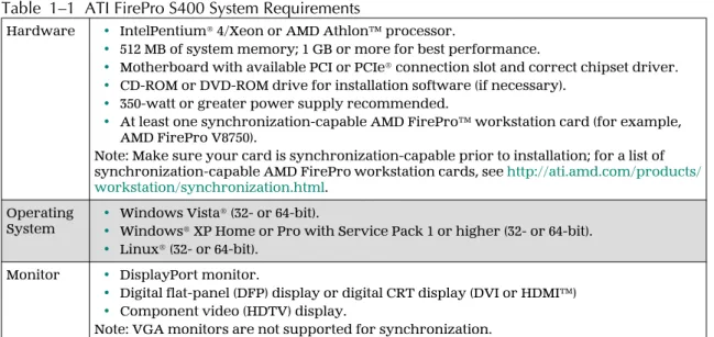
Table 1–1 ATI FirePro S400 System Requirements
Hardware • IntelPentium® 4/Xeon or AMD Athlon™ processor.
• 512 MB of system memory; 1 GB or more for best performance.
• Motherboard with available PCI or PCIe® connection slot and correct chipset driver.
• CD-ROM or DVD-ROM drive for installation software (if necessary).
• 350-watt or greater power supply recommended.
• At least one synchronization-capable AMD FirePro™ workstation card (for example, AMD FirePro V8750).
Note: Make sure your card is synchronization-capable prior to installation; for a list of synchronization-capable AMD FirePro workstation cards, see http://ati.amd.com/products/ workstation/synchronization.html.
Operating
System •• Windows Vista® (32- or 64-bit).Windows® XP Home or Pro with Service Pack 1 or higher (32- or 64-bit).
• Linux® (32- or 64-bit). Monitor • DisplayPort monitor.
• Digital flat-panel (DFP) display or digital CRT display (DVI or HDMI™)
• Component video (HDTV) display.
Note: VGA monitors are not supported for synchronization.
1.2 Recording Serial Numbers
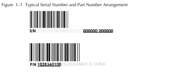
The serial number and part number on the synchronization module are required for product registration and customer care.
Record these numbers and retain them for future use.
1. Remove the synchronization module from the packaging.
2. Locate the label on the back of the synchronization module.
Figure 1–1 Typical Serial Number and Part Number Arrangement
1.3 Performing a Quick Installation
Experienced users and system administrators can follow these brief instructions for installing this ATI FirePro S400 synchronization module.
Other users should refer to Chapter 2 Installation (p. 3).
Note: A synchronization module is usually installed at the same time as one or more AMD FirePro workstation graphics cards.
1. Uninstall the drivers and software for any previously installed graphics card(s), if they are being replaced.
Note: If you are using a motherboard containing an on-board graphics solution and do not intend to use it as part of a multiple monitor display, disable it.
2. Shut down and disconnect your computer system.
3. Remove any installed graphics card(s), if they are being replaced.
4. Install your new AMD FirePro workstation graphics card(s) in the appropriate PCIe slot(s), if appropriate.
Refer to your workstation card's user guide, as necessary.
5. Install your ATI FirePro S400 synchronization module in an available PCI or PCIe slot, and connect it to your AMD FirePro workstation graphics card(s).
6. Reassemble and connect your computer system.
7. Install the latest drivers and configuration software for your AMD FirePro workstation graphics card(s) from the AMD Web site. For more information, refer to Drivers and Software (p. 5).
Chapter 2
Installation
This chapter details how to install the ATI FirePro S400 synchronization module in your system.2.1 Baseplate Connections
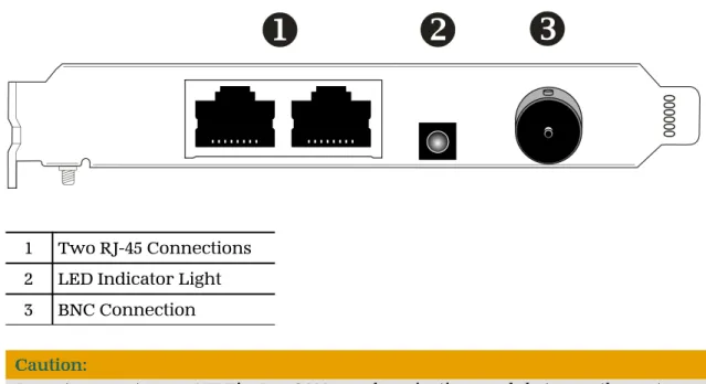
The following figure shows the display connections available on your ATI FirePro S400.
Note: Baseplate may not appear exactly as depicted.
Figure 2–1 ATI FirePro S400 Baseplate Connections
1 Two RJ-45 Connections 2 LED Indicator Light 3 BNC Connection Caution:
Do not connect your ATI FirePro S400 synchronization module to an ethernet network using the RJ-45 connections; damage may result.
Caution:
Do not connect your ATI FirePro S400 synchronization module to a cable distribution network using the BNC connection; damage may result.
2.2 Installing your Synchronization Module
Please read all installation instructions completely before you begin.Caution:
Do not connect your ATI FirePro S400 synchronization module to AMD FirePro™ workstation cards that are not on the supported list; damage may result.
1. Turn off your computer, display(s), and other peripheral devices.
2. Unplug the computer's power cord and disconnect all cables from the back of the computer.
Caution:
Wait approximately 20 seconds after unplugging the power cord before
disconnecting a peripheral or removing a component from the motherboard to avoid possible damage to the motherboard.
3. Remove the cover to your computer's case.
Note: If necessary, consult your computer's manual for help in removing the cover.
Caution:
Static electricity can seriously damage computer components. Discharge your body's static electricity by touching the power supply or the metal surface of the computer chassis before you touch any components inside your computer's case to avoid damaging them.
4. Unscrew or unfasten and remove any existing synchronization modules from your computer.
5. Locate an available PCI or PCIe® slot and, if necessary, remove the metal baseplate cover. Make sure all internal cables are clear of the slot.
6. Align your ATI FirePro S400 synchronization module with the slot and press it in firmly until the card is fully seated. You may need to hold open a locking tab on the slot with your finger when you seat the card.
7. Screw in or fasten the synchronization module securely.
8. Connect a 15-pin SATA power cable from the power supply to the synchronization module.
Note: Before installing a card that requires a supplementary power connection, make sure your existing power supply has such a connection available.
Important: Do not connect a SATA data cable to the data portion of the SATA connection on the synchronization board. The data pins are not used by this product.
9. Connect the GPU connections on the ATI FirePro S400 synchronization module with up to four AMD FirePro workstation cards installed in the PC.
Figure 2–2 Synchronization Module-to-GPU Connections
10. Make sure no internal cables are interfering with components inside the computer (for example, a cooling fan) and replace the computer cover.
11. Reconnect any cables that were disconnected during installation and plug in the computer's power cord.
12. Turn on any displays, and then your computer.
For information on setting up synchronization, see Chapter 4 Synchronization (p. 9).
2.3 Drivers and Software
Drivers are small but important programs that enable an operating system to communicate with a piece of hardware, such as a graphics card.
When you install a new graphics card, you must also install the driver and configuration software the card requires to function properly.
You do not need to install drivers specifically for your ATI FirePro S400. This
functionality is included in the AMD FirePro drivers. Consult the user guide for your AMD FirePro workstation graphics card for driver installation procedures.
Note: When reinstalling drivers, always uninstall any previous drivers that are on your system, even if they are for the same graphics card. Always start “fresh.”
Chapter 3
ATI Catalyst Control Center
This chapter introduces the Catalyst™ Control Center, a graphical user application that provides access to the display features of your ATI FirePro S400 synchronization module.3.1 Overview
The Catalyst Control Center software provides access to the display features of your ATI FirePro S400 synchronization module. Use the software to fine-tune graphics settings, enable or disable connected display devices, and change the orientation of the desktop. Many features display previews of the changes before they are applied. The following configurations are available:
Basic View
A simplified view of the features that includes wizards to quickly make changes.
Advanced View
A powerful interface that enables complete configuration of the feature set of the graphics card.
Custom View
A customized view so that desired features can be accessed quickly.
For information on the individual features of the software, access the comprehensive in-program help system (see Accessing Catalyst Control Center Help (p. 8) or visit the AMD Customer Care Web site at http://ati.amd.com/support/).
3.2 Starting the Catalyst™ Control Center Software
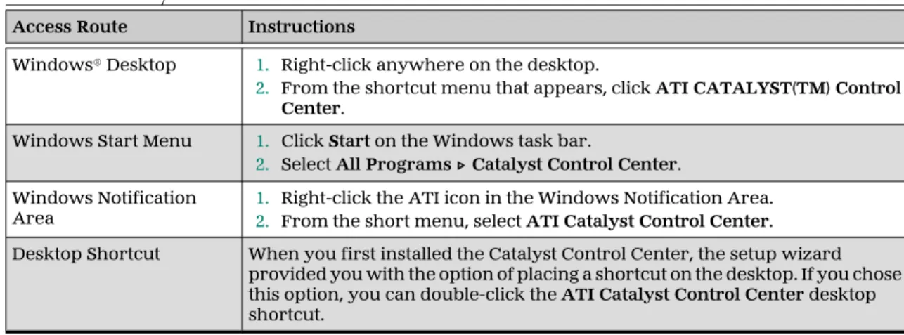
The following table shows the ways you can start the Catalyst Control Center software:Table 3–1 Catalyst™ Control Center Access Routes
Access Route Instructions
Windows® Desktop 1. Right-click anywhere on the desktop.
2. From the shortcut menu that appears, click ATI CATALYST(TM) Control Center.
Windows Start Menu 1. Click Start on the Windows task bar.
2. Select All Programs ▷ Catalyst Control Center. Windows Notification
Area 1.2. Right-click the ATI icon in the Windows Notification Area.From the short menu, select ATI Catalyst Control Center. Desktop Shortcut When you first installed the Catalyst Control Center, the setup wizard
provided you with the option of placing a shortcut on the desktop. If you chose this option, you can double-click the ATI Catalyst Control Center desktop shortcut.
3.3 Accessing Catalyst™ Control Center Help
Catalyst Control Center Help provides information on the features and concepts of your ATI FirePro S400 product. You can also use the Catalyst Control Center Help feature to access usage information, generate a problem report, and get software version details.
1. Open Catalyst Control Center in the Advanced view.
2. Choose one of the following options:
➭
Press the F1 key at any time to get specific help on the currently displayed information.➭
To browse the entire help contents, from either the Help or Options ▷Help menu, choose Help Contents.
➭
To access AMD's Web site, from either the Help or Options ▷ Help menu,choose Go to ATI.com. 8 ATI Catalyst Control Center
Chapter 4
Synchronization
4.1 Overview
In order for computing video applications to function properly with multiple displays or external video devices, special signal processing called “output locking” is required. Output locking synchronizes the display output of a GPU to a controlling signal, rather than allowing the display to refresh according to the state that a GPU finds itself in after being turned on. This controlling signal may be internally or externally generated, and function alone or in conjunction with other GPUs.
Output locking is required to ensure the video signals from multiple sources are synchronized, such as a video wall comprised of multiple small displays or when computer-generated graphics are combined with video from an external video camera.
Genlock (generator lock) is a type of output locking that synchronizes video outputs with an external reference signal generator.
Framelock is a synchronization method that uses output locking and also synchronizes 3D rendering on multiple GPUs.
Framelock and genlock for AMD FirePro™ workstation cards is provided by the ATI FirePro S400 synchronization module. Each synchronization module supports genlock and framelock for up to four GPUs per PC.
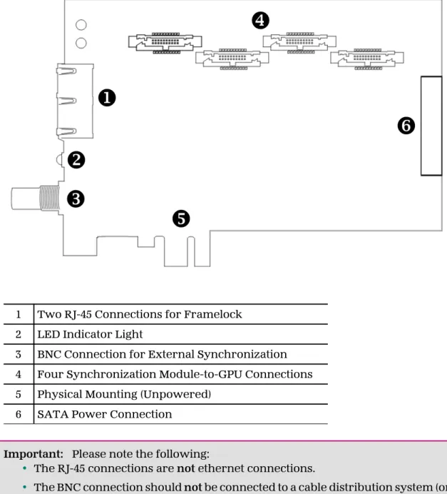
Figure 4–1 ATI FirePro S400 Side View
1 Two RJ-45 Connections for Framelock 2 LED Indicator Light
3 BNC Connection for External Synchronization 4 Four Synchronization Module-to-GPU Connections 5 Physical Mounting (Unpowered)
6 SATA Power Connection
Important: Please note the following:
• The RJ-45 connections are not ethernet connections.
• The BNC connection should not be connected to a cable distribution system (or equivalent).
4.2 Genlock
Genlock is an example case of output locking. 10 Synchronization
Genlock is commonly used in video post-production, nonlinear editing (NLE), and broadcast environment. Its use ensures that a workstation’s graphics output is locked to an externally generated signal, guaranteeing that devices (cameras, videotape recorders, character or title generators, and so on) work together effectively. Typically, a workstation user plugs a “house sync” signal into the graphics board— typically set at NTSC (U.S.), PAL (Europe), or HDTV rates—instructing the graphics board to trigger various edges of the external sync signal. The house sync signal connects to the BNC connection on the ATI FirePro S400.
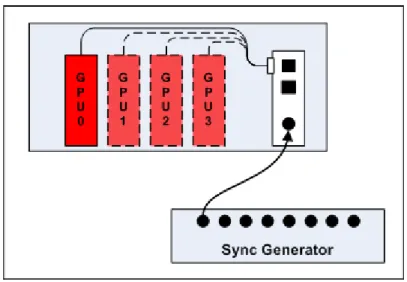
The following diagram shows a single PC with four GPUs connected to an ATI FirePro S400 synchronization module genlocked to an external signal generator.
Figure 4–2 Single PC with Four GPUs Genlocked to an External Signal Generator
When a display device is genlocked, the rate at which pixels are shown on the display is matched to a timing signal generated by an external signal source. This type of synchronization can be used to coordinate the pixel scanning of displays connected to a single computer or displays connected across multiple computers.
A device providing a timing signal is known as a timing server, whereas a device using such a signal is known as a timing client.
Timing Server. A timing server provides the timing signal to which timing clients can be synchronized. The source of this signal can come from one of the following:
• A signal fed directly into the house sync (BNC) connection on the sync module. • The display rate of a display device attached to the current computer.
Timing Client. A timing client synchronizes itself using the timing signal received from a timing server. Timing clients can be any number of the following:
• One or more displays attached to the current computer.
• Another computer connected downstream from the current computer via one or both of the RJ-45 connections on the sync module, essentially propagating the timing signal across a set of connected computers.
Use the Workstation ▷ Synchronization page of Catalyst™ Control Center to select
and configure timing clients and servers. You can also use this page to view the current status of external connections on the synchronization module.
Note: The settings on this page are available only if your computer is properly configured for synchronization. If necessary, follow the instructions on the page to correctly configure your computer.
4.3 Framelock
Framelock (sometimes called “frame synchronization”) refers to combining output locking with synchronized buffer swaps for 3D applications running across multiple windows. This type of synchronization can be used to coordinate the display of frames for applications on a single computer or across multiple computers. In framelocked systems with multiple computers, one (the timing server) is responsible for generating a synchronization signal for the others (the timing clients).
When graphics and video are displayed across multiple monitors on multiple computers, framelocked systems help maintain image refresh in sync. This allows images displayed on multiple monitors to create a large virtual canvas. For example, recent 4K resolution projection output devices require four DVI inputs to create one large 4K image.
Framelock is especially critical for stereo viewing, where the left and right fields must be in sync across all displays.
Framelock is most commonly used in simulation industries for displaying images to ensure seamless transition of objects from one window to another.
The following series of diagrams shows a variety of possible framelocking configurations.
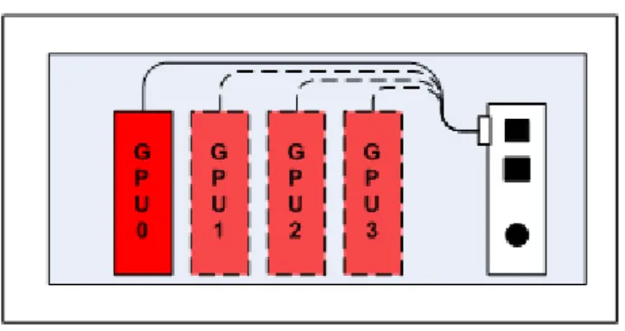
The following image shows a single PC with four GPUs connected to an ATI FirePro S400 synchronization module framelocked with an internal reference clock signal.
Figure 4–3 Single PC with Four GPUs Framelocked
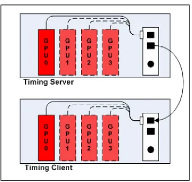
The following is an advanced framelock setup using two PCs with four GPUs each connected to an ATI FirePro S400 synchronization module synchronized with an internal timing server running on one of the PCs.
Figure 4–4 Two PCs with Four GPUs Each Framelocked
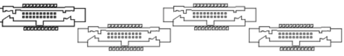
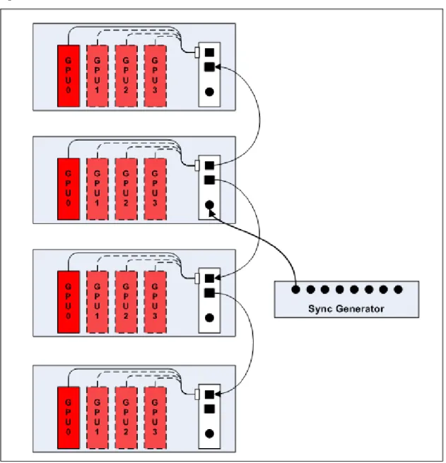
This diagram shows an advanced framelock and genlock setup using four PCs with four GPUs each; each computer is connected to an ATI FirePro S400 synchronization module synchronized with an external signal generator.
Figure 4–5 Four PCs Framelocked and Genlocked
4.3.1 Tips for Configuring Framelock
Framelock implementation is achieved using OpenGL extensions. For more information on whether your applications support these extensions, consult your software vendor.
Use the RJ-45 connections on the sync module to configure framelock across multiple computers. For framelock to be activated, all displays participating in a framelock configuration must be configured as active timing clients (through BNC/house sync or RJ-45).
Chapter 5
Reference
This chapter provides notices, troubleshooting tips, and customer care, warranty, and standards-compliance information.5.1 Workstation Customer Care
If you experience difficulties with your ATI FirePro S400 product, you can contact AMD Customer Care in the following ways.
5.1.1 Web
The AMD Customer Care Web site has number of helpful resources, including a knowledgebase of FAQs and the AMD FireGL™/AMD FireMV™/AMD FirePro™ Web Ticket Submission Page.
The Web site is complimentary and available at all times. The address is support.ati.com.
5.1.2 E-mail
Customer Care is available by e-mail at [email protected]. E-mails must have "workstation-support" in the subject line. This service is complimentary for registered users.
5.1.3 Telephone
Country Telephone
Number Language/Times Notes
US/Canada East Coast
1-866-284-2093 English:
9:00AM - 5:30PM EST (Mon-Thu) 9:00AM - 3:00PM EST (Fri)
Complimentary for registered users. Toll-free. US/Canada West Coast 408-749-2005 English: 2:30PM - 5:00PM PST (Mon-Thu) 12:00PM - 4:00PM PST (Fri)
Extended hours for West Coast customers; East Coast toll-free number also available.
Complimentary for registered users. International and local toll charges to California will apply.
United
Kingdom +44 (0)1276-803299 English:
10:30 - 17:00 CET (Mon-Fri)
Complimentary for registered users. International and local toll charges to the U.K. will apply.
France 0800-908-621 French/English:
10:30 - 17:00 CET (Mon-Fri)
Complimentary for registered users. Toll-free.
Italy 800-877-224 Italian/English:
10:30 - 17:00 CET (Mon-Fri)
Complimentary for registered users. Toll-free.
Germany +49 (0)89-4505-3199 German/English:
10:30 - 17:00 CET (Mon-Fri)
Complimentary for registered users. International and local toll charges to Germany will apply.
Argentina +0800-333-5277 Portuguese/Spanish:
7:00AM - 3:30PM EST (Mon-Fri) English:
7:00AM - 7:00PM (Mon-Fri)
Complimentary for registered users. Toll-free.
Brazil +0800-891-9068 Portuguese/Spanish:
7:00AM - 3:30PM EST (Mon-Fri) English:
7:00AM - 7:00PM (Mon-Fri)
Complimentary for registered users. Toll-free.
Mexico +001800-514-3276 Portuguese/Spanish:
7:00AM - 3:30PM EST (Mon-Fri) English:
7:00AM - 7:00PM (Mon-Fri)
Complimentary for registered users. Toll-free.
Other Latin American Countries
+1-905-882-3277 Portuguese/Spanish:
7:00AM - 3:30PM EST (Mon-Fri) English:
7:00AM - 7:00PM (Mon-Fri)
Complimentary for registered users. International and local toll charges to Canada will apply.
5.1.4 Surface Mail
Advanced Micro Devices Inc. Attention: Customer Care 1 Commerce Valley Drive East Markham, Ontario
L3T 7V9 CANADA
This service is complimentary.
5.1.5 Disclaimer
AMD Customer Care will work to resolve your issue and help you to get your product up and running. If your issue is not resolved, our technicians will determine whether the difficulty you are experiencing is the result of the product, whether your product contains a defect, and whether your product should be returned to AMD for warranty service.
AMD Customer Care is unable to assist with refunds, returns, or exchange-specific inquiries. If resolving the problem being experienced is critical to your decision to keep the product, it is your responsibility to ensure that you know and are within the period of time your reseller will allow for refunds, returns, or exchange.
AMD is not responsible for any expense incurred accessing Customer Care. It is expected that customers will review the expense associated with the available support options and will choose the method that best meets their needs and budget.
AMD Customer Care reserves the right to limit support options for products that are not registered or are at End of Life.
5.2 Workstation Warranty Service
For warranty service instructions visit ati.amd.com or contact one of our Customer Service Representatives.
5.2.1 Shipping
Before shipping any unit for repair, obtain an RMA number for warranty service. When shipping your product, pack it securely, show the RMA and serial number of the product on the outside, and ship prepaid and insured.
AMD will not be held liable for damage or loss to the product in shipment. Standard warranty service consists of repair upon receipt.
AMD reserves the right to replace the product with a serviced product at their sole discretion at any time.
You are responsible for the cost of shipping the product to AMD. AMD pays the cost of returning the product to you.
Products which are repaired under warranty are guaranteed for the remainder of the original warranty period. Repairing or exchanging a product does not start a new warranty period. If, at the time of repair, a product is already “out of warranty” or
within the last 90 days of the warranty period, AMD will guarantee the repair for the full 90 days. All other terms and conditions of the original warranty apply.
5.2.2 Limitations
This warranty is valid only if the online Product Warranty Registration form at ati.amd.com is successfully submitted within 30 days of purchase of said product. All warranties for this product, expressed or implied, will expire three (3) years from date of original purchase.
All accompanying cables and accessories are warranted for 90 days.
No warranties for this product, expressed or implied, shall extend to any person who purchases the product in a used condition.
The liability of AMD in respect of any defective product will be limited to the repair or replacement of such product. AMD may use new or equivalent-to-new replacement parts. Defective product will be sent in for repair or replacement only. AMD makes no other representations or warranties as to fitness for a particular purpose, merchantability or otherwise in respect of the product. No other representations, warranties or conditions, shall be implied by statute or otherwise. In no event shall AMD be responsible or liable for any damages, including but not limited to the loss of revenue or profit, arising:
• From the use of the product, as a result of any event, circumstance, action or abuse beyond the control of AMD; whether such damages be direct, indirect, consequential, special or otherwise and whether such damages are incurred by the person to whom this warranty extends or a third party
• From the loss of use of the product, as a result of any event, circumstance, action or abuse beyond the control of AMD; whether such damages be direct, indirect, consequential, special or otherwise and whether such damages are incurred by the person to whom this warranty extends or a third party.
Unauthorized repairs to an AMD board level product will void the warranty offered by AMD. AMD reserves the right to refuse to service any product which has been altered, modified, or repaired by non-AMD service personnel.
5.3 Additional Accessories
Additional and replacement cables, installation CDs, manuals, and other accessories for ATI products can be purchased from the online ATI store at ati.amd.com/online/accessories.
5.4 International Compliance Information
This section details the worldwide compliance information for this product, which is 18 Reference
5.4.1 FCC Compliance Information
This product complies with FCC Rules Part 15. Operation is subject to the following conditions:
• This device may not cause harmful interference.
• This device must accept any interference received, including interference that may cause undesired operation.
This equipment has been tested and found to comply with the limits designed to provide reasonable protection against harmful interference in a residential
installation. This equipment generates, uses and can radiate radio frequency energy and, if not installed and used in accordance with manufacturer's instructions, may cause harmful interference to radio communications. However, there is no guarantee that interference will not occur in a particular installation. If this equipment does cause harmful interference to radio or television reception, which can be determined by turning the equipment off and on, the user is encouraged to try to correct the interference by one or more of the following measures:
• Re-orient or relocate the receiving antenna.
• Increase the separation between the equipment and receiver.
• Connect the equipment to an outlet on a circuit different from that to which the receiver is connected.
• Consult the dealer or an experienced radio/TV technician for help. The use of shielded cables for connection of the monitor to the graphics card is required to ensure compliance with FCC regulations. Changes or modifications to this unit not expressly approved by the party responsible for compliance could void the user's authority to operate this equipment.
Complies with FCC 15.107 and 15.109. For further compliance information: Advanced Micro Devices, Inc.
62 Forest Street Marlborough, MA 01752 USA Tel: 508-303-3900
5.4.2 Industry Canada Compliance Statement
This Class B digital apparatus complies with Canadian ICES-003.
Cet appareil numérique de la Classe B est conforme à la norme NMB-003 du Canada.
5.4.3 CE Compliance Information
EMC Directive 2004/108/EC
CISPR 22:2008-09/EN 55022:2006—Class B: Limits and methods of measurement of radio disturbance characteristics of Information Technology Equipment.
CISPR 24:1997/EN 55024:1998—Information Technology Equipment—Immunity Characteristics—Limits and Methods of Measurements
5.4.4 Electrical Safety
Europe: The Low Voltage Directive—2006/95/EC
• EN 60950-1—Safety of Information Technology Equipment USA/Canada:
• UL 60950-1 (Information Technology Equipment—Safety—Part 1: General Requirements)
• CSA C22.2 No. 60950-1 (Information Technology Equipment—Safety—Part 1: General Requirements)
To meet UL safety requirements, the computer’s maximum room temperature should not exceed 40 °C.
5.4.5 Waste Electrical and Electronic Equipment (WEEE) Directive
Compliance
This product was manufactured by Advanced Micro Devices, Inc.
5.4.6 VCCI Class B ITE Compliance Information
5.4.7 KCC Certification Information
"Class B" Equipment (Household purpose info/telecommunications equipment) As this equipment has undergone EMC registration for household purpose, this product can be used in any area including residential area.
5.4.8 BSMI Certification Information
Appendix A
Glossary - Synchronization
2D
Acronym for “two dimensional,” a term applied to computer graphics that are “flat.” Typical desktop applications such as word processors, spreadsheet programs, or other programs that manipulate print or simple graphics (such as pictures or line art) are generally considered to be operating within a 2D
environment, even when they include simple three dimensional elements, such as buttons.
3D
Acronym for “three dimensional,” referring to computer graphics that appear to have volume and depth. Various modeling processes take the representation of a three dimensional object provided by the computer program and render it by using various lighting components, applying textures, and setting layers of transparency or opacity as required in order to produce a realistic representation of a three-dimensional object on a two-three-dimensional display.
Alpha Blending
Alpha blending is used in 3D graphics to create transparent or opaque effects for surfaces such as glass and water. Alpha is a transparency value, so the lower the value, the more transparent the image looks. It is also used in animations to produce such things as fading effects, where one image gradually fades into another.
Anisotropic Filtering
A technique that preserves the surface details of an object as it recedes into the distance by utilizing and blending together the object’s texture maps. This makes 3D objects appear more realistic as the detail of their surface texture is retained in a smooth, seamless fashion on the sections that move or fade away into the
background.
Anti-aliasing
A method that smooths out the jagged edges of a curved object. A black curved line on a white background displayed on a computer screen will have some jaggedness along its edges due to the inherent limitations of using discrete pixels to display the image. Anti-aliasing smooths out this jaggedness by filling in the white spaces between the jagged edges with varying shades of grey.
Aspect Ratio
The proportions of a display are expressed as a ratio of its width and height. Common ratios include 4:3 for TVs and CRTs, 5:4 for LCDs, and 16:9 for widescreen displays.
Catalyst™ Control Center
Catalyst™ Control Center (CCC) is a graphical user application providing access to the display features contained within the installed ATI hardware and software. CCC can be used to fine-tune various graphics settings, enable or disable connected display devices, change the orientation of a desktop, and much more.
Back Buffer
A type of offscreen memory used to provide smooth video and 2D graphics acceleration. This technique uses two frame buffers, so the process is often referred to as “double-buffering.” While the contents of one buffer are displayed, a second buffer, called the “back” buffer, holds the frame being worked on. In this way, users will only see complete, smooth frames displayed onscreen.
Bilinear Filtering
This filtering method reduces the blockiness caused when zooming into a 3D surface that is at a right angle to the viewer. A newspaper photo examined closely enough will show that the picture is made up of tiny dots. If the photo was enlarged it would start to look “blocky” and less distinct. This is also a problem for computer-generated images, especially for surface details.
Bit Depth
Refers to the number of data bits required to store color information about a pixel. Larger bit depth means a greater range of color information is capable of being encoded into each pixel. For example, 1 binary bit of memory can only encode to either “0” or “1.” So a graphical bit depth of 1 means that the display can only show two colors, the black and white of a monochrome display. Four-bit color depth is capable of displaying 16 colors because there are only 16 different combinations of 4 bits (0000, 0001, 0010... to 1111). Sixteen-bit color is capable of reproducing 65,536 colors, 24-bit color can display up to 16,777,216 individual colors, and 30-bit color can display up to one billion individual colors.
Bitmap
A bitmap is a graphic or character representation composed of individual pixels, arranged horizontally in rows. A monochrome bitmap uses one bit per pixel (bpp). Color bitmaps may use up to 32bpp, depending on the color depth selected.
Brightness
The amount of white or black that is applied to all colors onscreen. By making the screen “brighter” you are adding more white to it. This should not be confused with luminosity, which measures the actual light level emitted from the computer display.
Buffer
A name referring to portions of on-board video memory. One large buffer is always used to display images to the screen; this is the “display buffer.” The rest of offscreen memory is typically used by applications as back buffers, z-buffers, and texture buffers.
Color Component
Three color components (Red, Green, and Blue) combine in various intensities to determine the color of each pixel on the screen. The values of each color component are graphically represented by a corresponding color curve.
Color Correction
Correct discrepancies between the real color value and the way a screen displays it. Color discrepancies can be caused by a variety of sources, including the lighting conditions in the work area and gradual shifts in color over time on monitors or flat panel displays.
Color Curve
A color curve represents all possible intensity values (from 0 to 255) for a color component (Red, Green, or Blue). For each color curve, the horizontal axis
represents the input value (the color value a program wants to display), while the vertical axis represents the output value (the color value that the display driver will write to the screen). A value of 0 (in the lower left corner) represents the complete absence of that particular color, while a value of 255 (in the upper right corner) represents the “full” strength for that color.
Control Point
A control point is a user-created point on the color curve. Users can change the color of the screen by moving the control points with a mouse.
CRT
Acronym for “cathode ray tube,” which is the main component of computer monitors and TVs. Color CRTs use three separate electron beams fired through a shadow mask and onto the back of the glass screen. The electron beams activate separate red, green, and blue values in various strengths in order to produce a colored image.
Direct 3D®
Part of Microsoft®’s DirectX API designed for rendering 3D graphics on Windows® systems. It provides software developers with low-level access to functions on graphics cards, providing the type of performance necessary for intensive 3D applications such as games.
DisplayPort
DisplayPort is a digital display standard that became a VESA-approved standard in May 2006. HDMI™ is aimed primarily at the consumer electronic market, but DisplayPort was designed with computer displays in mind. It is scalable and extensible in terms of pixel depth and resolution, designed to work as a
comprehensive solution both for PCs and notebooks, which currently use different signaling standards (DVI and LVDS). DisplayPort is designed as a long-term
comprehensive replacement for VGA, providing a cost-effective, scalable, industry standard which will consolidate external (box-to-box) and internal (LCD panel) display connections.
Dithering
A computer graphics technique that takes advantage of the human eye’s tendency to mix two colors that are adjacent to each other to produce smooth boundary transitions. Dithering adds intermediate color values between two or more boundaries, producing smoother, more natural look to 2D images or 3D objects.
Dot pitch
Dot pitch specifies the sharpness of a monitor’s display. It is measured in
millimeters (mm) and is the distance between the individual phosphor sub-pixels in a CRT display or cells of the same color within an LCD display. The smaller the number, the sharper the image. The most common dot pitches for monitors range from .24 mm to .31 mm. Also, if a monitor with a .24 mm dot pitch is set to its highest possible resolution, the pixel size will equal the dot pitch. If the monitor is set to lower resolutions, the pixels will be comprised of multiple dots.
DVI
Acronym for “Digital Video Interface,” a standard video connection used on many current computer displays. There are three types of DVI connections: DVI-A (analog), DVI-D (digital), and DVI-I (integrated, capable of either analog or digital). It supports bandwidth video signals over 160 Hz, so it is most often used for high-resolution displays.
Flat Shading
A lighting technique that shades each polygon of a 3D object based on where the source of the light is and the angle of the polygon in relation to it. It enables relatively fast rendering of 3D objects, although it can make those objects appear "faceted" as each visible polygon is set to a particular color value, and consequently does not produce as realistic an effect as obtained when using Gouraud shading.
Fog
Term used to describe the blending of an object using a fixed color as objects are made to appear more distant from the viewer.
Frame Buffer
The portion of the memory buffer on the graphics card used to store the image being displayed. All rendering processes have been accomplished by this stage and this buffer contains only a one-to-one relationship of the data to be relayed to the display.
Framelocking
Framelocking synchronizes the video frames on multiple displays to a signal generated internally by the hardware (using output locking and, optionally, genlocking). This allows images displayed on multiple monitors to create a large virtual canvas. In addition, 3D rendering between GPUs is synchronized (swap locking).
Frames Per Second
In terms of 3D graphics, refers to the rate at which the graphic processor can render new screens per second. Higher rates equals better, more naturalistic performance for such things as games set in a 3D environment. Sometimes abbreviated to “fps.”
Gamma
Sometimes confused with brightness, gamma actually refers to the correction that is applied to any display device in order to produce more gradual increases or decreases in the perceived brightness for that device. A change in gamma produces a non-linear change in the color curve, ensuring that perceived changes in color and intensity are consistently applied.
Genlocking
Genlocking synchronizes video outputs with an external reference signal generator. This ensures that video output sources from multiple video output devices (such as workstations, cameras, or video recorders) are combined or switched properly.
Gouraud Shading
A shading method used to produce a smooth lighting effect across a 3D object. A specific color is used at each vertex of a triangle or polygon and interpolated across the entire face.
GPU
GPU is an acronym for “Graphics Processing Unit.” The GPU powers the operations of a graphics card including support for 2D/3D and video.
HDCP
HDCP is an acronym for “High-Bandwidth Digital Copy Protection.” It is a form of digital rights management designed to protect copyright of signals being
transported across DVI or HDMI™ connections. Several international regulatory 26 Glossary - Synchronization
HDMI™
HDMI™ is an acronym for “High Definition Multimedia Interface.” It is a 19-pin connector used for transferring combined digital audio and video. HDMI™ supports standard, enhanced, and high-definition digital video signals, and is designed for use with VCRs, DVD players, personal computers, and set-top boxes. A DVI adapter can be used to transfer the video signal to an HDMI™-capable display, although audio must be transferred from a different route, as DVI output does not support audio.
Hue
Refers to a specific color within the visible spectrum of light, defined by its dominant wavelength. A light wave with a central tendency within the range of 565-590 nm is visible as yellow. In the standard RGB color space used by most computer displays, hue refers to a coordinate of the color as described by its red, green, and blue values, minus any additional brightness or saturation values for that color.
HydraVision™
HydraVision™ is ATI’s multi-monitor management software, enabling users to manage the display of multiple windows and applications across two or more adjacent monitors. It also includes a range of productivity features designed to effectively manage applications in this environment.
Keyframe Interpolation
This feature is also known as “morphing.” In an animation, a start and end point are picked as the key frames. In a 3D rendering, the start point could have a character with a neutral expression, and the end point could have that same character smiling. Additional frames are interpolated (inserted) between the two keyframes in order that morphs (transforms) the image so that there is a smooth transition between the key frames.
KTX Buffer Region Extension
This OpenGL programming term refers to a feature that rapidly updates portions of the display of 3D modelling applications that change very quickly, or have been moved or occluded. It does this by optimizing the storage of buffer regions in the graphics card’s memory buffer. Other applications are typically not adversely affected when this is enabled.
Lighting
In 3D computer graphics, refers to aspects and quality of the virtual light source being used to make an object visible. Lighting can strongly affect the “mood” of a scene. For example, a “harsh” light could be a bare lightbulb that is glaringly bright on the objects closest to it while casting strong shadows in the background. A “softer” light would be more diffuse and not cast shadows, such as you would get outdoors on a typical overcast day.
Mipmapping
The most memory-intensive aspect of 3D graphics are the textures that give an object its realism (like wood, marble, leather, and cloth). Because objects in real life become less detailed as they move farther away from the viewer, 3D programmers simulate this by using less detailed, lower resolution texture maps on distant objects. These texture maps are merely scaled down versions of the main texture map used when the object is up close, and they use less memory.
Offscreen Memory
An area of memory used to preload images so that they can be quickly drawn to the screen. Offscreen memory refers to all of the remaining video memory not taken up by the front buffer, which holds the contents of the display screen currently visible.
OpenGL
Short for “Open Graphics Library,” this is an industry standard for cross-platform 3D graphics development. It consists of a large number of functions that can be called upon in various programs, such as games, CAD, and virtual-reality systems, to produce complex 3D objects from simpler, more "primitive" building blocks. Implementations currently exist under Windows®, Mac OS® X, and various forms of Unix, including Linux®.
Output Locking
Output locking is the ability to synchronize the display output of a GPU to a
controlling signal, rather than allowing the display to refresh according to the state that a GPU finds itself in after being turned on. This controlling signal may be internally or externally generated, and alone or in conjunction with other GPUs.
PCI
Acronym for “Peripheral Component Interconnect,” which is the specification for a type of computer bus used for attaching computer peripherals to a computer’s motherboard. PCI encompasses both integrated motherboard components (such as built-in graphical processors) and peripherals that fit into an expansion card slot, such as a separate graphics card. PCI replaced the older ISA and VESA bus
standards, and was itself superseded by the AGP standard for the main graphics card bus.
PCI Express® (PCIe®)
The successor standard to the PCI and AGP bus standards, with a significantly faster serial communications system, further opening up bandwidth for more
communications between such peripherals as graphics cards and the computer’s CPU. PCIe® cards can come in several physical configurations, the fastest currently being X16, which is typically used for graphic cards, and X1, typically used for other peripherals, such as separate multimedia cards.
Pipeline
In relation to computer graphic processors, refers to the number of separate arithmetic units available for rendering the output on a display. In general, more pipelines available on a graphical processor means there are more 3D rendering capabilities available, increasing overall 3D performance.
Pixel
All computer images are made up of tiny dots. Each individual dot is called a pixel, a word created from the term “picture element.” A pixel is the smallest indivisible unit of a digital image and can be only a single color. The size of the pixel depends on how the display resolution has been set. The smallest size a pixel can be is determined by the display’s dot pitch, which is measured in millimeters (mm).
Refresh Rate
Also referred to as “vertical refresh rate.” This is the rate at which a monitor or television can redraw the screen from top to bottom. NTSC television systems have a refresh rate of approximately 60 Hz whereas computer displays typically have refresh rates of 75 Hz or more. At refresh rates of 70 Hz and lower, screen flicker is often noticeable.
Rendering
Rendering refers to the final drawing stages where the 2D image that appears on a display is derived from its 3D descriptions. What appears on the display may look 28 Glossary - Synchronization
Resolution
The resolution of any display is the number of pixels that can be depicted on screen as specified by the number of horizontal rows against the number of vertical columns. The default VGA resolution of many video cards is capable of displaying 640 rows of pixels by 480 columns. The typical resolution of current displays is set to higher values, such as 1024x768 (XGA), 1280x1024 (SXGA), or 1600x1200 (UXGA).
Saturation
Refers to the intensity of a specific hue (color). A highly saturated hue is vivid and intense, whereas a less saturated hue appears more grey. A completely
unsaturated color is grey. In terms of the RGB color model, a fully saturated color exists when you have 100% brightness in one of the three channels (say, red) and 0% in the two others (green and blue). Conversely, a fully desaturated color is one where all of the color values are the same. Saturation can therefore be thought of as the relative difference between the values of the channels.
Shadow Mask
In CRT monitors, the shadow mask is a metal plate full of tiny holes that is attached to the inside of the glass screen. It focuses the beams from the electron guns at the back of the CRT. The distance between these holes is called the dot pitch.
Specular Highlight
The bright, usually small, intense light reflected from a 3D surface with a high refraction value. From the intensity and spread of this highlight users can differentiate between a “hard,” smooth surface, such as metal or porcelain, or a “soft,” textured surface, such as fabric or skin.
Swap Locking
Swap locking refers to the ability of multiple GPUs (in one computer or across multiple computers) to perform their 3D buffer swaps at the same time. Buffer swaps occur when the back buffer, which has been filled by the GPU during rendering, becomes the front buffer, which the display engine uses to refresh the display. This ensures that all GPUs in a framelocked system are presenting their information at the same time and eliminates “tearing” artifacts that occur when a framebuffer is swapped while the display is in mid-refresh.
Swap locking comprises two parts: members of a system reporting their readiness to swap (that is, they have finished their rendering task), and then all GPUs
performing their swaps when all their peers have reported readiness.
Texel
Short for “texture element,” the 3D equivalent of a pixel, describing the base unit of the surface of a 3D object, such as a sphere; for a 2D object, such as a circle, the base unit is a pixel.
Texture Mapping
In computer graphics, two-dimensional textured surfaces are referred to as texture maps. Texture mapping is the process by which a two-dimensional surface gets wrapped around a three-dimensional object so that the 3D object takes on the same texture qualities. For example, if you take a 2D textured surface that looks like cloth and wrap it around a 3D sphere, the sphere will now appear to have a cloth-like surface.
Texture Preference
Texture Preference is a feature enabling the user to select the texture quality level for the surface of a 3D object. Selecting the highest quality possible will provide the most realism, although it may also have some impact on the performance of any 3D intensive application.
Trilinear Filtering
A sampling method used to produce realistic-looking 3D objects. Trilinear filtering averages one of the bilinear filter mipmap levels along with the standard mipmap samples.
Vertex Shader
Three-dimensional objects displayed on a screen are rendered using polygons, each of which is made up of intersecting triangles. A vertex is a corner of a triangle where it connects to another triangle, and each vertex carries a considerable amount of information describing its coordinates in 3D space, as well as its weight, color, texture coordinates, fog, and point size data. A vertex shader is a graphics processing function that manipulates these values, producing such things as more realistic lighting effects, improved complex textures such as hair and fur, and more accurate surface deformations such as waves rippling in a pool or the stretching and wrinkling of a character’s clothes as he or she moves.
VGA Connector
A type of graphics connector, sometimes also called an analog connector. It is the most common type of video connector available, consisting of 15-pins set in three rows. VGA is an acronym for “Video Graphics Array,” which is also the name for the video resolution mode of 640x480 pixels, the lowest standard resolution supported by virtually all video cards.
Z-buffer
The portion of video memory that keeps track of which onscreen elements can be viewed and which are hidden behind other objects. In the case of a 3D image, it keeps track of which elements are occluded by the foreground in relation to the user’s perspective, or by another 3D object.
Index
C
connector 10 BNC 10 RJ-45 10
sync module to GPU 10