Microsoft
System
Center
Building a
Virtualized Network
Solution
PUBLISHED BY Microsoft Press
A Division of Microsoft Corporation One Microsoft Way
Redmond, Washington 98052-6399
Copyright © 2014 by Microsoft Corporation (All)
All rights reserved. No part of the contents of this book may be reproduced or transmitted in any form or by any means without the written permission of the publisher.
Library of Congress Control Number: 2014931254 ISBN: 978-0-7356-8310-5
Printed and bound in the United States of America.
First Printing
Microsoft Press books are available through booksellers and distributors worldwide. If you need support related to this book, email Microsoft Press Book Support at
[email protected]. Please tell us what you think of this book at http://www.microsoft.com/learning/booksurvey.
Microsoft and the trademarks listed at http://www.microsoft.com/en-us/legal
/intellectualproperty/Trademarks/EN-US.aspx are trademarks of the Microsoft group of companies. All other marks are property of their respective owners.
The example companies, organizations, products, domain names, email addresses, logos, people, places, and events depicted herein are fictitious. No association with any real company, organization, product, domain name, email address, logo, person, place, or event is intended or should be inferred.
This book expresses the author’s views and opinions. The information contained in this book is provided without any express, statutory, or implied warranties. Neither the authors, Microsoft Corporation, nor its resellers, or distributors will be held liable for any damages caused or alleged to be caused either directly or indirectly by this book.
Acquisitions Editor: Anne Hamilton
Developmental Editor: Karen Szall
Editorial Production: Megan Smith-Creed
Copyeditor: Megan Smith-Creed
Contents
Introduction vii
Chapter 1
Key concepts
1
Introducing Contoso Ltd ... 1
Architecture ... 2
Virtualized network components ... 3
Logical network ... 3
IP and MAC address pools ... 5
Uplink port profiles ... 6
Network adapter port profiles ... 7
Port classifications ... 8
Logical switches ... 8
Virtual machine networks ... 10
Deploying the solution ... 11
Chapter 2
Logical networks
13
Reviewing key concepts ... 13Getting started with logical networks ... 14
Logical network design ... 15
Introducing the Contoso network ... 16
Step 1: Mirror physical networks ... 17
Step 2: Networks with different purposes ... 17
Step 3: Determine isolation requirements ... 22
Step 4: Define network sites ... 41
Step 5: Deployment ... 44
Naming conventions ... 44
What do you think of this book? We want to hear from you! Microsoft is interested in hearing your feedback so we can continually improve our books and learning resources for you. To participate in a brief online survey, please visit:
Chapter 3
Port profiles
47
Uplink port profiles ... 47
What is defined in an uplink port profile? ... 48
How are uplink port profiles used? ... 51
How many uplink port profiles do you need? ... 52
Naming conventions ... 65
Network adapter port profiles ... 65
What is defined in a network adapter port profile? ... 66
How are network adapter port profiles used? ... 67
How many network adapter port profiles do you need? ... 68
Naming conventions ... 71
Chapter 4
Logical switches
73
Logical switches ... 73What is a logical switch? ... 74
Logical switches versus virtual switches ... 77
Logical switches versus VMware distributed switches ... 78
Planning your logical switch design ... 78
Upgrading from Hyper-V Server 2008 ... 79
Quality of Service (QoS) ... 79
Virtual network interface cards (vNICs) ... 84
Network adapter teaming ... 85
Virtual high bandwidth adapters (HBAs) ... 86
How many logical switches do you need? ... 86
Enhancing logical switch capabilities ... 92
VMM unavailability ... 94
Chapter 5
Deployment
95
Preparing for deployment ... 95Deploying logical switches ... 96
Untagged host management network adapter ... 97
Known deployment issues ... 109
Limitations for an existing NIC team ... 109
Deployment fails if host is out-of-scope ... 110
Deployment fails when using different network adapter types ... 110
Chapter 6
Operations
113
Operational scenarios ... 113Logical switches ... 114
Logical networks ... 118
VM networks ... 121
What do you think of this book? We want to hear from you! Microsoft is interested in hearing your feedback so we can continually improve our books and learning resources for you. To participate in a brief online survey, please visit:
Introduction
ccording to the Hyper-V Network Virtualization Overview found at
http://technet.microsoft.com/en-us/library/jj134230.aspx, Network Virtualization “provides virtual networks to virtual machines similar to how server virtualization provides virtual machines to the operating system. Network Virtualization decouples virtual networks from the physical network infrastructure and removes the constraints and limitations of VLANs and hierarchical IP address assignment from virtual machine provisioning. This flexibility makes it easy for customers to move to Infrastructure as a Service (IaaS) clouds and efficient for hosters and datacenter administrators to manage their infrastructure while maintaining the necessary multi-tenant isolation, security requirements, and supporting overlapping Virtual Machine IP addresses.”
Although the benefits of this approach are very clear, designing and implementing a solution that delivers the promised benefits is both complex and challenging; architects, consultants, and fabric administrators alike can often struggle to understand the different components and concepts that make up a solution.
Who should read this book?
Much of the published material covering Network Virtualization today is very much focused on the how, the set of tasks and things that you need to do (either in the console or through Windows PowerShell) to set up and configure the environment. In this book, we take a very different approach and instead, consider the what, with a view to helping private and hybrid cloud architects understand the overall architecture, the role each individual component plays, and the key decision points, design considerations, and the best practice recommendations they should adopt as they begin to design and build out a virtualized network solution based on Windows Server 2012 and Microsoft System Center 2012 SP1 (or later).
In summary, this book is specifically designed for architects and cloud fabric administrators who want to understand what decisions they need to make during the design process and the implications of those decisions, what constitutes best practice, and, ultimately, what they need to do in order to build out a virtualized network solution that that meets today's business requirements while also providing a platform for future growth and expansion.
What topics are included in this book?
Although this book, part of a series of specialized guides on System Center, provides you with insight into the various components of a virtualized network solution primarily based upon Windows Server 2012 and System Center 2012 SP1, many of the concepts, advice, and guidance outlined in respect of best practice are unchanged for the R2 release.
The vast majority of the book is focused on architecture and design, highlighting key design decisions and providing best practice advice and guidance relating to each major component of the solution. The remaining chapters are more operational and discuss how to deploy and how to manage some of the common changes that might need to be made post deployment.
Chapter 1: Key concepts A virtualized network solution built on Windows Server 2012 and System Center 2012 SP1 depends on a number of different components, and this chapter outlines the role each of these components plays in the overall solution and how they are interconnected.
Chapter 2: Logical networks This chapter takes a look at some of the main reasons why you would (or would not) create a logical network, provides an overview of the key considerations, outlines some best practice guidance, and describes a process for identifying the set of logical networks that are needed in your environment
Chapter 3: Port profiles This chapter discusses the different types of port profiles in Microsoft System Center 2012 Virtual Machine Manager (VMM)— uplink port profiles and network adapter port profiles—describes what they are used for, and provides detailed guidance for how and when to create them.
Chapter 4: Logical switches This chapter covers logical switches, essentially templates for Hyper-V switches, which allow you to consistently apply the same settings and configuration across multiple hosts and ensure that any Hyper-V switches you deploy and configure using a logical switch remain compliant with it.
Chapter 5: Deployment This chapter builds on the material discussed in previouschapters and walks through common deployment scenarios, highlighting known issues (and workarounds) relating to the deployment and use of logical switches in your environment
Chapter 6: Operations Even after having carefully planned a virtual network solution, things outside of your immediate control may force changes to your virtualized network solution. This chapter walks you through some relatively common scenarios and provides recommendations, advice, and guidance for how best to deal with them.environment. Other than in Chapter 5, which focuses on deployment issues and considerations, and Chapter 6, which covers managing change to the environment post deployment, you will find very few examples of code. This is by design: our focus here is not to provide details of how you achieve a specific goal but rather to identify what you need to do to build out a solution that will meet the needs of your business and provide a platform for the future.
Once you have designed a solution using the guidelines documented in this book, you will be able to make effective use of the some of the excellent materials and examples available in the Building Clouds blog (http://blogs.technet.com/b/privatecloud/) to assist you with both solution deployment and ongoing management.
Acknowledgments
The authors would like to thank Stanislav Zhelyazkov (MVP), Hans Vredevoort (MVP), Phillip Moss (NTTX), and Greg Cusanza, Thomas Roettinger, Artem Pronichkin, and Cristian Edwards Sabathe from Microsoft for providing valuable feedback and suggestions on the content of the book. Without their contributions this book would not be as thorough nor as complete; so our thanks once again for their time and efforts in making this happen.
Errata & book support
We’ve made every effort to ensure the accuracy of this content and its companion content. Any errors that have been reported since this content was published are listed on our Microsoft Press site at oreilly.com:
http://aka.ms/SCvirtnetsol/errata
If you find an error that is not already listed, you can report it to us through the same page. If you need additional support, email Microsoft Press Book Support at
Please note that product support for Microsoft software is not offered through the addresses above.
We want to hear from you
At Microsoft Press, your satisfaction is our top priority, and your feedback our most valuable asset. Please tell us what you think of this book at:
The survey is short, and we read every one of your comments and ideas. Thanks in advance for your input!
Stay in touch
Key concepts
virtualized network solution built on Windows Server and Microsoft System Center depends on a number of different components. It is important to understand the role these components play in the solution and how they are interconnected, especially if you need to troubleshoot issues with connectivity or have to make changes to your solution to reflect updated business requirements.
This chapter will:
Introduce an example organization
Identify the different components of a virtualized network solution
Provide an overview of each component and how to configure it
Describe how these components are used to configure virtualized networking on multiple Hyper-V host computersIntroducing Contoso Ltd.
Since a lot of planning considerations and best practice approaches are discussed in this book, we’ve use an fictitious organization (Contoso) to help put many of these points into context. Contoso Ltd. is a service provider—otherwise known as a hoster—that offers Infrastructure as Service (IaaS), Platform as a Service (PaaS), and Software as a Service (SaaS) to customers from datacenters located in the United States (Seattle) and the United Kingdom (Reading).
Contoso has more than 1,000 employees worldwide, with the majority of its employees employed in its development and operations center in Reading. Revenues in the last financial year topped £100 million for the first time. Contoso has decided to deploy and use Windows Server 2012 and Microsoft System Center 2012 SP1 for its hosting services moving forward because the company recognizes this platform’s ease of deployment and the cost and
efficiency benefits in terms of infrastructure provisioning, infrastructure monitoring, application performance monitoring, automation and self-service, and IT service management.
design choices are applicable to all customers that want to use Windows Server and System Center to create a cost effective and highly efficient private or hybrid cloud solution.
Architecture
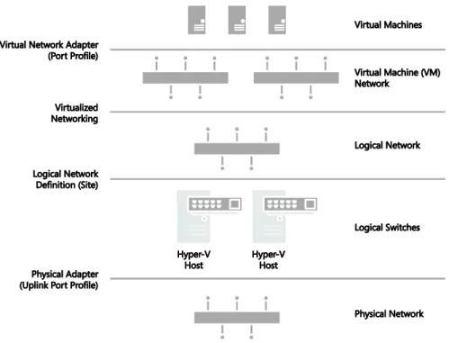
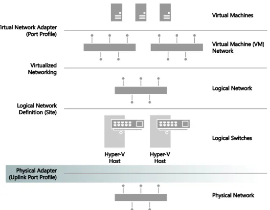
Figure 1-1 is a simplified diagram that illustrates the different layers and components that make up the architecture of a virtualized networking solution based on Windows Server and System Center. In this diagram, the physical network and Hyper-V host computers are at the bottom and the deployed virtual machines and services are at the top. On the right are the names of each component; the labels on the left describe how these components are connected. For example, a logical switch is connected to a logical network via a logical network.
FIGURE 1-1 Architecture of a virtualized network solution.
Virtualized network components
There are a number of different components in a virtualized network solution that must be defined and configured before you can begin to take full advantage of the features and flexibility provided by Windows Server 2012 Hyper-V and System Center 2012 SP1.
Logical networks Theserepresent an abstraction of the underlying physical network infrastructure and enable you to model the network based on business needs and connectivity requirements.
Uplink port profiles Theseare applied to physical network adapters as part of logical switch deployment and define the set of logical networks that should be associated with those network adapters. They also specify whether and how multiple network adapters (in a given host computer) using the same uplink port profile should be teamed.
Network adapter port profiles These are templates that define offload settings, bandwidth policies, and security settings for virtual network adapters.
Port classification This is a user friendly label that can be linked to a network adapter port profile. (Port classifications are not shown in Figure 1-1.)
IP address pools Theseallow VMM to automatically allocate static IP addresses to Windows-based virtual machines that are running on any managed Hyper-V, VMware ESX, or Citrix XenServer host.
MAC Address Pools If virtual machines connected to the logical network will obtain IP addresses from a static IP address pool, you must also configure the virtual machine to use a static MAC address. You can either specify the MAC address manually or have VMM automatically assign a MAC address from a MAC address pool.
Logical switches These bring together uplink port profiles, native port profiles, port classifications, and switch extensions that are relevant to a particular physical or logical network.
Virtual machine networks These provide the network interface through which a virtual machine will connect to a particular logical network.Logical network
The VMM documentation says that “A logical network is used to organize and simplify network assignments for hosts, virtual machines, and services. As part of logical network creation, you can create network sites to define the VLANs, IP subnets, and IP subnet/VLAN pairs that are associated with the logical network in each physical location.” The
service-level agreements. You can find more information on logical networks and how to determine how many you need in your environment in Chapter 2, “Logical networks.”
At Contoso, Hyper-V hosts supporting production workloads are situated in two physical locations, Reading and Seattle, with each site using a different VLAN and IP subnet range. Virtual machines running production workloads on hosts in the Reading Datacenter need to use VLAN18 and have an IP address in the 192.168.99.0/24 subnet, where those in Seattle should use VLAN 100 and have IP address in the 192.168.199.0/24 subnet.To allow the Production logical network to be supported in both of these locations, two network sites must be defined as shown in Figure 1-2.
FIGURE 1-2 Defining sites within a logical network.
The Reading network site is scoped to Hyper-V hosts deployed in Reading. It defines the VLAN and IP subnets that will be used by virtual machines that connect to the Production logical network when running on a Hyper-V host in the Reading location. The other network site is scoped to the Seattle host group and essentially defines the VLANs and subnets that will be used by virtual machines deployed in Seattle.
Note that scoping the logical network to a host group in the network site as shown above does not actually make the logical network available on any of the hosts within the group. It simply prevents the logical network from being associated with hosts that are not within the target groups. To make the logical network available on a given host, you need to associate the logical network with a physical network adapter on that host.
FIGURE 1-3 Logical networks associated with a physical network adapter.
You might expect that the result of this configuration, once it has been deployed to hosts in both locations, would be that a virtual machine connected to the Production logical network can be moved between hosts in Reading and Seattle without requiring any additional configuration. The destination Hyper-V host in the new location ensures that the virtual machine is configured with the VLAN and IP address appropriate for the logical network in the new physical location.
Moving existing virtual machines between sites like this is certainly possible, but there are a few caveats. The main one is that the IP address assigned to the virtual machine will not be changed during migration. If the physical network is a stretched LAN, meaning the same IP subnet is present in both locations, then the virtual machine will continue to communicate on the network once it has been moved. If, as in the earlier example, each site has its own VLAN and IP subnet, then although you will be able to successfully move the virtual machine to a new location, it will have an incorrect VLAN/IP address for that location.
NOTE A virtual machine connected to a virtual machine network that uses Network Virtualization where the Production logical network has been enabled can be moved between hosts in Reading and Seattle without requiring any additional configuration.
IP and MAC address pools
If you associate one or more IP subnets with a network site, you can also create static IP address pools for those subnets. Static IP address pools make it possible for VMM to
address pool, you can also define a reserved range of IP addresses that can be assigned to load balancers as virtual IP addresses. VMM automatically assigns a virtual IP address to a load balancer during the deployment of a load-balanced service tier. If you define the IP address inside the virtual machine manually, VMM will detect the IP address and the pool to which it belongs (if defined) at the next refresh cycle. This process helps to ensure that VMM does not assign the selected IP address to another virtual machine.
NOTE When isolating network traffic using Network Virtualization, which is covered in more detail in Chapter 2, the logical network also has a relationship with deployed virtual machines in that each machine must be allocated an IP address from one of the IP pools that have been defined for that logical network. An IP address from this pool, otherwise known as provider address (PA), is routable between Hyper-V hosts.
If you configure a virtual machine to obtain its IP address from a static IP address pool, you must also configure the virtual machine to use a static MAC address. You can either specify the MAC address manually or have VMM automatically assign a MAC address from either a central MAC address pool or one that you have created for a specific network site.
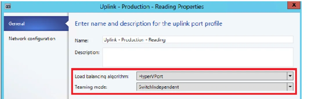
Uplink port profiles
Uplink port profiles are applied to physical network adapters as part of logical switch deployment and define the set of logical networks that should be associated with those network adapters. They also specify whether and how multiple network adapters (in a given host computer) using the same uplink port profile should be teamed.
In most cases, a single uplink port profile will be required for each physical network unless you need to define custom connectivity rules, have multiple physical networks, or wish to restrict logical networks to specific hosts within a given physical location, in which case you will need to create additional uplink port profiles. You can find more details on uplink port profiles as well as a process to help you determine whether you need to create more than one of them in Chapter 3, “Port profiles.”
At Contoso, a number of hosts in Reading and Seattle have been dedicated to Production workloads, and port profiles and logical switches (which are discussed in Chapter 4, “Logical switches”) will be used to ensure the host computers in each location are configured consistently. Assuming that the servers in each location have the same type of physical connectivity, only a single uplink port profile should be required.
configure the adapter with the VLANs and subnets (as listed in the Reading Production network site) that will be used by virtual machines in that location.
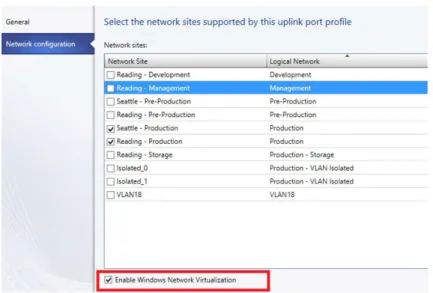
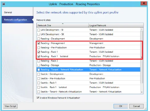
FIGURE 1-4 Defining network sites (and logical network connectivity) in an uplink port profile.
In the example above, multiple network sites are supported by a single uplink profile. When the uplink port profile is applied to a physical network adapter as part of logical switch deployment, VMM checks each network site in the uplink to determine if the host is "in scope" for that site. If it is in scope, , the network adapter will be associated with all of the logical networks that are defined in that network site.
Network adapter port profiles
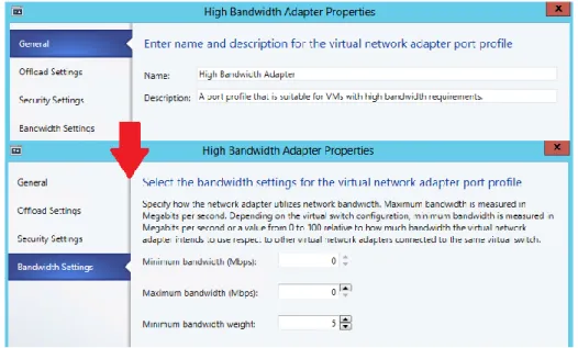
Network adapter port profiles, which are called native port profiles for virtual network adapters in VMM 2012 SP1 and Hyper-V port profiles for virtual network adapters in the R2 release, are
FIGURE 1-5 Defining bandwidth policy in port profiles.
NOTE Although native port profiles allow you to enable network settings for a virtual network adapter, to be effective some of these (IPsec task offloading, for example) will require additional configuration on the host computer.
Network adapter port profiles and how you can configure and use them are covered in Chapter 3, but to summarize, network adaptor port profiles are used to define the Quality of Service (QoS) settings you want to apply to specific virtual machines and network cards that allow you to take advantage of some of the features provided by your host hardware.
Port classifications
Port classifications are linked to network adapter port profiles. They hide the details, settings, and configuration of a network adapter port profile from the end user. When connecting a virtual machine to the network, end users will see a list of port classifications they can select from, for example "high bandwidth" or "low bandwidth," but they can’t see the priority, bandwidth settings, and IEEE priority value behind a particular configuration. Port classifications are linked to network adapter port profiles and will discussed in Chapter 3.
Logical switches
you can use to create Hyper-V virtual switches on any of the host computers that connect to the network. When you use a logical switch to create a Hyper-V switch on a host computer, you select the most appropriate combination of port profiles, classifications, and switch extensions from the list of those defined in the logical switch. Generally, a new logical switch is required for every physical network in your environment. But if you plan to restrict some logical networks to a limited set of hosts, as in the example organization in this chapter, or if you have custom connectivity requirements, you may need to create additional logical switches. Chapter 4 covers the design rationale for logical switches.
Given that the example organization has three physical networks (Datacenter, Provider, and Storage) we will need to create at least three logical switches based on the above guidelines. However, only a limited number of hosts in Reading and Seattle will run production workloads that need to be associated with the Production logical network created earlier. The key question is whether an additional logical switch is required to support this environment.
Technically, the Production uplink port profile can be included in the logical switch created for the Datacenter network and the administrator can choose the most appropriate settings and capabilities for the relevant host. VMM can even actively prevent administrators from using any of the Production uplinks when they use the logical switch to create a Hyper-V virtual switch on a host that should not be associated with the Production logical network.
As shown in Figure 1-6, the new logical switch will contain the Production uplink port profile and a single network adapter port profile that will ensure that network traffic from these hosts and the virtual machines running on them are tagged with the required IEEE priority flags and are provided with the appropriate bandwidth guarantees. The port
classification “High Bandwidth – Production” shown in Figure 1-6 is simply a friendly name for the network adapter port profile and will be displayed to users when they connect their virtual machines to the network.
NOTE The previous example does not include any switch extensions; however, you might want to include these in your logical switch to allow you to monitor network traffic, use quality of service (QoS) to control how network bandwidth is used, enhance the level of security, or otherwise expand the capabilities of a Hyper-V virtual switch created on a host computer. If these enhanced services should be restricted or deployed only on a limited number of hosts, you may need to consider creating an additional logical switch.
MORE INFO You can find more information on Hyper-V virtual switches at
http://technet.microsoft.com/library/hh831823.
Virtual machine networks
In terms of overall architecture, virtual machine (VM) networks are the final component to consider in this short overview since they provide the (network) interface through which a virtual machine connects to a particular logical network, as shown in Figure 1-7. You can find more details on VM networks in Chapter 2. Since all virtual machines must be connected to a VM network to be able to use and access network resources in VMM, it follows that you will need at least one VM network for each logical network.
FIGURE 1-7 Mapping a VM network to a logical network.
It is important to note that the relationship between a VM network and its (host) logical network is established when the VM network is initially created and cannot be changed afterward. To use a different logical network, you will need to delete the existing VM network and create a new one.
Deploying the solution
You can of course configure the network settings and properties on each Hyper-V host manually or by using Windows PowerShell, but to ensure consistency and simplify
management across multiple hosts it is far more efficient to define the required properties and capabilities within port profiles and logical switches using VMM as described. When a logical switch is applied to a network adapter in a Hyper-V host, VMM uses the information contained in the logical switch and the selected uplink port profile to create a Hyper-V virtual switch on the host and associate the network adapter with the required logical networks, VLAN, and IP subnets. It therefore follows that the host must be a member of a VMM host group that has been scoped to those logical networks. If the host is not in an appropriate host group, deployment of the switch will fail with an Out Of Scope error.
NOTE If you apply the same logical switch and uplink port profile to two or more adapters, the two adapters will be teamed, assuming that this option has been defined in the logical switch. The option to add or remove adapters will be available only if Uplink Mode has been set to Team.
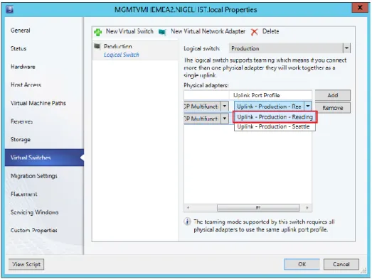
Figure 1-8 shows the logical switch being applied on one of the new servers. The administrator has selected the Production uplink port profile to ensure that the selected network adapters are configured with the VLAN and IP Subnets that are appropriate for this location.
FIGURE 1-8 Deploying a logical switch on a Hyper-V host.
Using this information, VMM will create a Hyper-V virtual switch on the host and use the logical networks, VLAN, and IP subnets from the uplink port profile to configure these properties on the selected network adapters. Once the switch has been deployed, the physical network adapter can no longer be configured through the UI or PowerShell; any further changes to the logical networks, VLAN, and IP subnets for the network adapter must be configured in the uplink port profile.
Logical networks
ogical networks represent an abstraction of the underlying physical network infrastructure and enable you to model the network based on business needs and connectivity
properties. The Microsoft System Center 2012 Virtual Machine Manager (VMM)
documentation indicates that “A logical network is used to organize and simplify network assignments for hosts, virtual machines, and services. As part of logical network creation, you can create network sites to define the virtual local area networks (VLANs), IP subnets, and IP subnet/VLAN pairs that are associated with the logical network in each physical location.” It goes on to state that logical networks can be used to describe networks with different purposes, create traffic isolation, and even support traffic with different types of service-level agreements.
This chapter will:
Identify where logical networks fit into a virtualized network solution
Determine how and why logical networks are created automatically
Introduce a step-by-step process for logical network design
Consider how to optimize design to support network traffic isolation
Discuss the use of network sites, IP, and MAC address pools
Try to help answer the question “How many logical networks do I really need?”Reviewing key concepts
To help set context for this discussion, begin by referring to Figure 1-1 in Chapter 1, "Key concepts." This diagram illustrates the different layers that make up the architecture of a virtualized networking solution, highlighting logical networks and their connections to other components of the architecture. The key takeaways from this diagram for Chapter 2 are:
Logical networks are connected to a logical switch via a logical network definition (otherwise known as a network site) and to virtual machine (VM) networks via virtualized networking.In addition, since all virtual machines must be connected to a VM network to access network resources in VMM, it follows that you will need to define at least one VM network for each logical network that will be accessed by virtual machines.
Although not shown in Figure 1-1, logical networks also have a relationship with clouds. VMM uses this relationship to scope or otherwise restrict the list of VM networks that are available to users during virtual machine placement. To be placed in a cloud, the virtual machine must be connected to a VM network that is linked to a logical network associated with that cloud. Chapter 6, "Operations," will examine this relationship and how it is used.
Getting started with logical networks
At least one logical network must be associated with a given host computer for it to support deployed virtual machines and services. To help ensure this is the case, VMM verifies that physical network adapters on all new host computers are associated with one or more logical networks. If no such association exists, VMM checks to see if a logical network exists with the same name as the first DNS suffix labelon each network adapter. For example, in the case of a server called REA-HST-01.Corp.contoso.com, VMM would expect to find a pre-created logical network called Corp. If it does find a match, VMM will automatically associate the host network adapter with the selected logical network. If it does not, VMM will create a new logical network with that name (Corp) and make the necessary association with the host.
IMPORTANT If the new host computer is connected to a number of different physical networks, VMM could potentially create a new logical network for every physical network the host is connected to.
FIGURE 2-1 Turning off automatic logical network creation.
If you leave this setting on initially, you can turn it off later, but be aware that VMM will not allow you to delete any default logical networks that have existing associations with network adapters in your host computers. You will need to associate these adapters with different logical networks first. You may also have to remove VM networks and any other objects that have dependencies on these logical networks before you can successfully delete them.
Logical network design
The goal in this chapter is to present a step-by-step approach to logical network design, starting from the basic principle that you should begin as simple as possible and then add additional logical networks only where there is a compelling business or technical reason to do so. The process can be summarized as follows:
1. First, define a set of logical networks that initially mirror the physical networks in your environment.
2. Define networks that have a specific purpose or perform a particular function within your environment.
3. Identify which logical networks need to be isolated and how that isolation will be enforced, either through physical separation, VLAN/PVLAN, or Network Virtualization.
4. Determine the network sites, VLANs, PVLANs, and IP pools that need to be defined for each logical network you have identified.
As usual, defining and adhering to a sound naming convention for logical networks is important both to promote understanding and to help simplify management and reduce cost.
Introducing the Contoso network
To set this process in context, take a closer look at the physical network in the example service provider, Contoso Ltd., and identify the set of logical networks that will be needed to support this company’s specific business requirements. Although your own network layout and business requirements might be different from Contoso’s, the design process, key decision points, and the implications of certain design choices are applicable in all cases.
As shown in Figure 2-2, Contoso has three physical networks in each of its datacenters:
Corporate (internal) workloads and services are hosted on the Datacenter network.
Customer (tenant) network traffic is on the Provider network.
Storage devices are accessed via the Storage network.The physical separation between customer, storage, and corporate network traffic improves security, simplifies infrastructure management, and removes potential competition between different types of network traffic.
FIGURE 2-2 Physical networks in each Contoso datacenter.
The following sections outline the five step logical network design process for Contoso, identifying the set of logical networks the company needs to support its business and technical requirements and highlighting some of the key decision points and best practice
Step 1: Mirror physical networks
It seems reasonable to begin by creating logical networks that map to and mirror each of the physical networks in the environment, but you should expect to create many more logical networks than you have physical networks. Indeed, one of the key benefits of logical networks is that they provide flexibility, allowing you to separate computers and network services with different business purposes, isolate network traffic, or support different workloads with network service levels, all without having to change the physical network infrastructure. With that said, creating one logical network for each physical network is a very useful beginning.
Since Contoso has three physical networks (Datacenter, Provider, and Storage), the assumption is that that three logical networks will be required to support this environment, one for each physical network, as shown in Figure 2-3. As you will discover in the sections that follow, you will likely need to create additional logical networks to support specific business and technical requirements. But as a guiding principle, you should always start with as simple a design as possible, adding logical networks only where there is a clear and justifiable reason for doing so.
FIGURE 2-3 Logical networks that mirror the physical network.
Step 2: Networks with different purposes
It’s a basic assumption that computers and devices that connect to and use the same network should be able to communicate with each other with routers or gateway devices used to connect different networks should this be required. This general principle also holds true for logical networks, so the next step in the design process is to identify the different groups of users, applications, and network services that will use each of the physical networks and determine whether there is a need to separate them to enforce security, ensure privacy (isolation), simplify management and administration, or simply to ensure that network traffic from certain groups is provided with the required Quality of Service (QoS).
physical network to determine whether this design is appropriate for the groups of computers and network services that will use them.
Datacenter physical network
The Datacenter physical network at Contoso Ltd. carries network traffic generated by
corporate (internal) services and applications as well as network traffic needed to support and maintain the cloud fabric (infrastructure services such as host management, live migration, and cluster heartbeat). Step 1 established a single logical network, Datacenter. The question is whether this design is appropriate for the workloads on this network.
CORPORATE (INTERNAL) SERVICES
If development, test, and production network traffic all share the same physical network, you will invariably want to differentiate these workloads. In the example Contoso environment, development, pre-production, and production workloads will coexist on the Datacenter physical network. To make this environment easier to manage, three separate logical networks are created, one for each workload type, as shown in Figure 2-4. Note that network adapter port profiles (explained in Chapter 3, “Port profiles”) will be used to apply the required properties and capabilities, including bandwidth limitations and IEEE priority tags, to virtual machines and services that connect those networks.
FIGURE 2-4 Using logical networks to differentiate workloads.
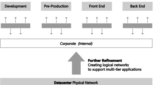
The VMM documentation suggests that you also consider creating separate logical networks for the front end (web servers) and the back end components (application and database servers) of multi-tier applications. The primary benefit of such an approach is that it allows you to use network sites to define the set of VLANs and IP subnets that will be used by virtual machines in each tier and, further, to apply a different set of security settings and capabilities to each network through the use of port profiles.
Since Contoso is expecting to deploy and use multi-tier applications, the logical network design for internal (corporate) workloads needs to be refined with the creation of separate logical networks for the front end and back end components of these services, as shown in Figure 2-5. Note that production workloads that are not part of any multi-tier application will be expected to connect to and make use of the Back End logical network.
FIGURE 2-5 Dividing Production into front end and back end logical networks.
Traffic prioritization, network bandwidth control, and support for multi-tier applications are just a few of the reasons why you might consider creating logical networks for corporate (internal) workloads. Security concerns, the requirement to isolate certain workloads, and the need to restrict the host computers on which a given business service can run are also key considerations. Consider each case on its merits, reviewing the business case as well the technical requirements, with the aim of creating logical networks only when really necessary and keeping the design as simple and as easy to understand as possible.
CLOUD INFRASTRUCTURE
operations, live migration, hardware management, and host/guest management. Will a single logical network suffice for all of these operations or will it be necessary to create logical networks for each type of infrastructure traffic?
In keeping with the guiding principle to create logical networks only when necessary, the key decision point is whether to apply different capabilities, bandwidth controls, and network traffic prioritization to each one of these services. If the answer is no, then a single logical network will suffice. If the answer is yes for a limited number of these services (backup and live migration are normally good candidates), then a dedicated logical network for those services should be created, with the remainder using a shared infrastructure logical network.
Contoso has chosen to create logical networks for each of the infrastructure services, as shown in Figure 2-6. You might choose to implement this differently, adding or removing logical networks from the design based upon your requirements and the capabilities of your network infrastructure.
FIGURE 2-6 Using logical networks to differentiate cloud infrastructure services.
Provider physical network
MORE INFO Some organizations are primarily service providers and others are enterprise customers who provide hosted software and services internally or externally to their customers or business partners. Planning to separate internal or cloud infrastructure and customer (tenant) workloads is relevant to both types of organization. You can find more details at http://technet.microsoft.com/en-us/library/hh831441.aspx.
In designing a logical network solution for a provider network such as the one at Contoso, you should first consider the compute models the organization intends to support. Essentially this means determining whether workloads from multiple customers will run on the same physical hardware (shared compute), if certain host computers and resources will be dedicated to a single customer (dedicated compute), or if you will support both of these scenarios. A good starting point for the design is a single logical network for the shared compute workloads and a separate logical network for each customer that uses dedicated resources.
For customers with dedicated resources, host groups and network sites in VMM will associate the logical network with the host computers within each physical location that has been allocated to ( reserved for) that customer. This is covered in much more detail in Chapter 5, “Deployment.”
Contoso, like many service providers, allows customers to choose which of these approaches works best for them. Customer workloads may be hosted on either shared or dedicated resources, with the latter attracting a price premium. Two customers have opted for physical servers dedicated to their workloads, with the remainder utilizing the shared compute model. The logical network design to support this model of operation (ignoring isolation) is shown in Figure 2-7. The design assumes that as new customers with dedicated compute requirements are onboarded to the service, additional logical networks will be added to the solution.
In reality and as discussed for the Datacenter network, you may need to extend this initial model, breaking out (defining) additional logical networks to support a specific hosted service or to support a specific business or customer requirement.
Storage physical network
The final physical network for Contoso is dedicated to a single purpose: providing access to shared storage. A single logical network that maps directly to the physical network (as initially conceived in Step 1 of this process) is therefore quite appropriate. Note that if Contoso were to use multiple IP-based storage technologies (such as iSCSI and SMB) on the physical network, each of these technologies would likely be allocated its own logical network.
Step 3: Determine isolation requirements
At the end of Step 2, you should have arrived at a set of candidate logical networks for each physical network in your environment. The next step is to review the isolation requirements for each logical network you have identified so far, something which is clearly an important consideration for service providers hosting external customer workloads and enterprise customers needing to isolate network traffic from certain business groups or restricted (special) projects. These security requirements may lead you to create additional logical networks or at least further refine your logical network design.
To understand this concept, consider the basic assumption stated earlier: computers that connect to and use the same network should be able to communicate with each other through routers that connect different networks together, enabling inter-network communication. This principle holds in most cases. Indeed, where there is a business need to split off or otherwise isolate certain workloads for security, to improve performance, or simply to facilitate more effective control of network traffic, the best solution is to create a new network, either physically or via virtual networks (VLAN or PVLAN technology), place all of the appropriate computers and services on that network, and update the network routing tables and security policy to facilitate inter-network communication. This approach will be familiar to both enterprise customers and service providers, with the latter often using dedicated VLANs and PVLANs to isolate different customers from one another.
Historically, logical networks in VMM effectively modeled this behavior by enabling resources connected to a given logical network to communicate with any other resource on that same network, with inter-network communication handled via a router or gateway device. The problem with this solution for service providers (hosters) was that each customer invariably required a distinct logical network, which led to the creation of hundreds if not thousands of logical networks within VMM, resulting in performance issues and increased complexity and management overhead.
are linked to the logical network instead of associated with physical host computers, adding, deleting, and making changes to these VM networks is easier than making changes to logical networks. Multiple VM networks may be linked to each logical network, removing the need for service providers to create separate logical networks for each of their customers.
FIGURE 2-8 VM networks’ relationship to logical networks.
If there is no need to separate or otherwise isolate network traffic from certain machines, only a single VM network linked to the logical network is required. As described earlier, multiple VM networks are required to host workloads for multiple customers (tenants) on the same logical network, with each tenant isolated from and unaware of any others.
In VMM, you can isolate VM networks by using either traditional VLAN (or isolated PVLAN) solutions or, if you are using Windows Server 2012 as your host operating system, by
implementing Network Virtualization. The latter option addresses the scale limitations associated with a traditional VLAN solution and allows tenants to “bring their own network” or otherwise extend their network into your environment.
MORE INFO The different ways that VMM can isolate network traffic are well illustrated by the Logical Networks section of the "Networking in Virtual Machine Manager" poster that can be downloaded from the Microsoft Download Center at
http://www.microsoft.com/en-us/download/details.aspx?id=37137.
VLAN/PVLAN technology and others by using Network Virtualization. Should you need to use multiple approaches in your environment, you will need to return to Step 2 above and create a separate logical network for each isolation method.
MORE INFO There is a practical limit of approximately 2,000 tenants and 4,000 VM networks per VMM server. If you expect to approach either of these scale limitations you will most likely need to introduce additional VMM servers and use Service Provider Foundation to manage this environment. You should follow the same process described in this section to identify and create logical and VM networks for each VMM server you deploy. You can find more information on Service Provider Foundation at
http://technet.microsoft.com/en-us/library/jj642895.aspx.
No isolation
Isolation is necessary only in cases where a logical network will be used by multiple customers (tenants). Logical networks created for corporate (internal) workloads, cloud infrastructure services, and logical networks that are dedicated to a specific customer are all single tenant, meaning that traffic isolation is optional.
FIGURE 2-9 Creating a VM network with no isolation.
NOTE In VMM 2012, virtual machines were directly connected to logical networks. When customers using this release upgraded to SP1, VM networks configured for No Isolation were automatically created for each of these logical networks. Virtual machines that existed prior to the upgrade were then connected to the new VM network linked to their original logical network.
FIGURE 2-10 VM network direct access to the logical network.
NOTE For logical networks that will not be used by virtual machines, generally those dedicated to infrastructure services like storage and live migration, you may not need to create VM networks at all.
VLAN isolation
FIGURE 2-11 Configuring a logical network for VLAN isolation.
Each VLAN must be allocated to a network site. Multiple VLANs can exist with the same site, as shown in Figure 2-12, but each one will be totally isolated from any of the others.
FIGURE 2-12 Defining network sites for VLAN isolation.
FIGURE 2-13 Allocating a VLAN (network site) to a VM network.
Although you can manually choose which VLAN should be allocated to a VM network, VMM also provides for automatic assignment. This is useful where customers are allocated a VLAN from a pool rather than being given an assigned VLAN. In these cases, a VLAN is randomly assigned from the pool when you define a new VM network and is returned and available for re-use when that VM network is deleted. Note that once all of the available network sites have been allocated, no further VM networks may be linked to this logical network until additional VLANs are added or some of the existing VM networks are deleted.
FIGURE 2-14 Logical network design for VLAN isolation.
There are a number of limitations to using VLANs to isolate network traffic, most significantly the scalability limits. Only 4,095 VLANs are permitted per physical network. PVLANs may be used to work around this limitation, but at a cost of increased complexity. The cost of management, level of complexity, and the risk of error also increase significantly at high scale. These issues may not be of direct relevance to enterprise customers since, in general, they do not need to manage very large numbers of networks at this scale, but these are major considerations for service providers that provide hosted services to a large number of external customers.
VLAN isolation is expected to remain common practice in many enterprise deployments given its relative simplicity and ease of management at smaller scale. Service providers (hosters), however, can be expected to use alternative isolation technologies to help work around VLAN scale limitations given their need to manage a much larger number of networks.
PVLAN Isolation
A PVLAN consists of a primary and secondary VLAN pair. Each machine that is part of a PVLAN pair can be configured in one of three modes as shown in Figure 2-15. In promiscuous mode, hosts are on the primary VLAN and can communicate directly with resources on both the primary and secondary VLANs. In community mode, the secondary VLAN represents a community. Direct communication is permitted only with hosts in the same community and those that are connected to the primary PVLAN in promiscuous mode. In isolated mode, direct communication is permitted only with promiscuous resources on the primary PVLAN.
FIGURE 2-15 The three modes for PVLAN isolation.
VMM only supports isolation mode and has no concept of primary (promiscuous) or community modes. What this means in practice is that a virtual machine connected to a PVLAN in this release is completely isolated from any other resources on the network. The only device it can directly communicate with is the default IP gateway. While this may feel like a severe limitation, there are a number of scenarios that work quite well in this configuration, the most common example of which is front end web servers. In this specific scenario, all of the web servers in a web farm are placed on a single network subnet but are otherwise completely isolated from each other, PVLANs in this context, helping to simplify management and improve overall security.
NOTE Similar functionality to community mode can be achieved by adding an additional network adapter to the VM and connecting this adapter to a VM network on which Network Virtualization has been enabled and to which all of the other community resources are also connected.
FIGURE 2-16 Enabling PVLAN isolation.
The Network Site page of the Create Logical Network Wizard includes a subtle but important difference for PVLANs. In addition to the primary VLAN, the Associated VLANs And IP Subnets section contains an additional column called Secondary VLAN. You should associate each primary VLAN and secondary PVLAN with a network site within the logical network, as shown in Figure 2-17. You can also define multiple PVLANS in the same network site as needed.
Only one PVLAN can be in isolated mode per primary VLAN, and you should take care to ensure that a different primary VLAN ID is used in each network site you create. The ID you use for the PVLAN, however, may be the same in each site. In fact, using the same ID for the isolated PVLAN is actually recommended to ensure consistency and simplify management.
As discussed, VM networks are needed for VMs to connect to and use the logical network. Each VM network you create is directly mapped to exactly one of the PVLANs that have been defined for that logical network. As a result, you can have only as many VM networks as you have defined PVLANs. As shown in Figure 2-18, the Create VM Network Wizard displays only those PVLANs that have not already been allocated to an existing VM network. Note that the wizard does not offer the option for automatic assignment even though the UI suggests that this is possible.
FIGURE 2-18 Allocating a PVLAN (network site) to a VM network.
as shown in Figure 2-19. In this example, PVLAN 5 is designated as the isolated PVLAN for consistency across all primary VLANs. Your implementation may be different.
FIGURE 2-19 Logical network design for PVLAN isolation.
Network Virtualization
Network Virtualization provides administrators with the ability to create multiple virtual networks on a shared physical network. In this approach to isolation, each tenant receives a complete virtual network, which includes support for virtual subnets and virtual routing. Tenants can even use their own IP addresses and subnets in these virtual networks, even if these conflict with or overlap with those used by other tenants. Further, since virtual networks are defined entirely in software, it is unnecessary to reconfigure the physical network (unlike VLAN and PVLAN solutions) to onboard or remove tenant networks or to make changes to reflect new business requirements.
NOTE You can find more details on this approach at
http://blogs.technet.com/b/windowsserver/archive/2012/08/22/software-defined- networking-enabled-in-windows-server-2012-and-system-center-2012-sp1-virtual-machine-manager.aspx.
In Figure 2-20, Tenant A has two virtual subnets. A virtual router automatically created by Windows Server 2012 Hyper-V connects the two subnets for this tenant and allows VMs on each subnet to communicate with each other. Tenant B has a single virtual subnet but still has its own virtual router. The virtual subnet ID and routing domain ID shown in the diagram are used by Hyper-V host computers to differentiate network traffic and routing for each of the tenants.
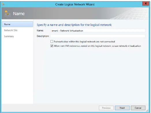
When using Network Virtualization, the logical network design is relatively simple: create a single logical network for all of your customers that will be isolated from each other using Network Virtualization and configure the properties of the network with the Allow New VM Networks Created On This Network To Use Network Virtualization option, as shown in Figure 2-21.
FIGURE 2-21 Configuring a logical network to support Network Virtualization.
You need to create network sites to define the VLANs and IP subnets that are to be associated with the logical network in each physical location. Assuming you specify VLANs in your network sites, the physical network must be able to route network traffic between them. The VLANs in this case are used by the network administrator for ease of management and to control broadcast traffic; they are not used as an isolation mechanism. Note that these VLANs exist on the Hyper-V host server Parent Partition only—tenant VMs are unable to gain access to them.
FIGURE 2-22 Defining a provider address IP pool for a network site.
FIGURE 2-23 VM network isolation using Hyper-V Network Virtualization.
You also need to define the IP subnets for each VM network, setting out the IP addresses that will be used by VMs connected to that network, as shown in Figure 2-24. These addresses, known as the Consumer Address (CA), are completely separate from any other tenant and from the logical network. Tenants can therefore use their own IP addresses and subnets in their virtual networks, even if these appear to conflict with or otherwise overlap with those used by other tenants. Again, each tenant may be allocated multiple subnets, as shown in Figure 2-24.
FIGURE 2-24 Defining consumer IP subnets.
FIGURE 2-25 Logical network design for Network Virtualization.
The virtual networks shown in Figure 2-25 have no external connectivity by default, meaning that VMs connected to them will be able to communicate only with other virtual machines on the same virtual network. You can use a VPN gateway device to provide a VPN tunnel to a nominated external network or a Hyper-V Network Virtualization (HNV) gateway device to allow virtual machines on the virtual network to communicate with other networks in the local datacenter.
Externally defined networks
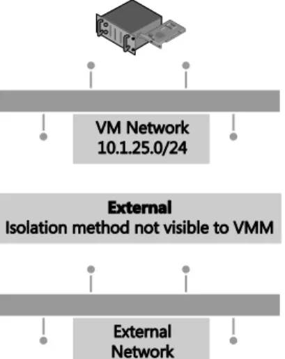
Network administrators can also configure network settings or capabilities such as logical networks, network sites, and IP pools, by using a third-party (vendor) network management console. In this case, the VMM administrator uses a virtual switch extension manager to import the externally defined settings directly into VMM. This approach allows network specialists to focus on and define the logical network, leaving the VMM administrators free to concentrate on the VM networks and the services that are to be offered to end customers. In this context, the logical network becomes a “black box” to VMM administrators in that they can use networks imported through the virtual switch extension manager but have no insight into how the network is constructed, nor do they have any visibility into the method of network
FIGURE 2-26 In externally defined networks, the isolation method is not visible to VMM.
Externally defined networks are included in this text only to note that VMM administrators need to work closely with their counterparts on the network team to make sure that a consistent model and design structure is being followed. Ideally, network administrators should plan the network configuration in partnership with VMM administrators to ensure that both parties agree on naming conventions and standards for how to define the fabric.
MORE INFO You can find more information on virtual switch extension managers in VMM and how to make use of them at
http://technet.microsoft.com/en-us/library/jj614619.aspx.
Key points
Considering the logical networks created for Contoso, there appears to be little or no
requirement to isolate any of the logical networks defined on top of the Datacenter or Storage physical networks. That being said, you could easily justify using some form of isolation for front end web servers (assuming they were accessible from the public Internet) that were connected to the Datacenter network or for specialized servers and workloads that need to be isolated from others. You need to assess each logical network and determine what, if any, isolation methodologies you should apply in your environment.
supported by the physical network. Network Virtualization clearly offers the most
comprehensive and scalable solution but requires NVGRE gateway devices to allow virtual machines to communicate with networks in the same datacenter or VPN gateway devices to facilitate communication with a defined external network. VLAN/PVLAN isolation can be readily used, is well understood, and is supported by most existing network hardware, but has management issues at scale. The decision, ultimately, will be based on your business strategy, current and forecast growth patterns, and how quickly and easily you can acquire and deploy network gateways that support NVGRE and software-defined networking.
Step 4: Define network sites
At this point in the process, you can start to consider implementation details, reviewing each of the logical networks that you identified during the earlier parts of the process to decide where (i.e., in which physical location) they need to be deployed and to determine the set of network sites, IP pools, and MAC address pools needed to make the networks available and used in those locations.
Physical locations and host servers
It makes sense to make some logical networks available in all physical locations. Many of the cloud infrastructure networks, such as management, storage, and live migration, clearly are relevant to and should be made available everywhere while the availability of others should be restricted to specified locations. If your organization’s development team is located in a single location, it might be reasonable to ensure that the logical network you create for development workloads would be available only on servers in that location.
Having identified the physical locations on which a given logical network will be available, the next decision point is which of the Hyper-V hosts in that location should be configured to support it. Again, it makes sense that some of the logical networks should be made available on all of the host computers in that location, the logical networks you define for cloud infrastructure such as Management and Storage clearly being the most obvious candidates, though there may well be exceptions to this general rule. For example, not all servers will have access to network attached storage.
FIGURE 2-27 Creating host groups for dedicated servers.
Network adapters in Windows Server 2012 Hyper-V servers can be associated with multiple logical networks. However, there is no internal routing between them. If you want to allow virtual machines and host services configured on one logical network to communicate with those on another, you will need to deploy a router or gateway device.
Network sites (logical network definitions)
Network sites, otherwise known as logical network definitions, are used to define the VLANs and IP subnets that are to be associated with the logical network in each physical location. However, it is unnecessary to define network sites for all of your logical networks. The following key points replicated from the Configuring Logical Networking in VMM Overview section of the VMM documentation (available at
http://technet.microsoft.com/en-us/library/jj721568.aspx) set out the guidelines that will help you determine whether you need to define a network site for the logical network in a given physical location:
If you want to use DHCP that is already available on the network, and you are not using VLANs, you do not have to create any network sites but as a recommended best practice, you should always aim to do so.
If using VM networks that use Network Virtualization, you must create at least one network site and associate at least one IP subnet with the site as mentioned earlier. You can also assign a VLAN to the network site, as appropriate. Creating a network site with an IP subnet makes it possible to create an IP address pool for the logical network, which is necessary for Network Virtualization.If the VM networks you create will not use Network Virtualization as an isolation mechanism, the following guidance applies: