FPE 596
Culminating Project
Military Maintenance Hangar
Prepared By:
Eliot Jordan
July 14, 2020
a | P a g e
This project report is a result of a class assignment; it has been graded and accepted as
fulfillment of the course requirements. Acceptance of this report in fulfillment of the course
requirements does not imply technical accuracy or reliability. Any use of information in this
report is done at the risk of the user. These risks may include, but may not be limited to,
catastrophic failure of the device or infringement of patent or copyright laws. California
Polytechnic State University at San Luis Obispo and its staff cannot be held liable for any use or
misuse of the project.
Key Words
Available Safe Egress Time (ASET) Required Safe Egress Time (RSET) International Building Code (IBC) Life Safety Code (LSC)
b | P a g e
Executive Summary
This report describes the building code compliance of a military aircraft hangar. The facility is evaluated for both prescriptive code compliance and for a performance-based compliance via the use of design fires analyzed with computer programs Fire Dynamics Simulator (FDS) and occupant egress analyzed with Pathfinder software as well as hand calculations utilizing Excel.
The prescriptive code analysis is done based upon a combination of Unified Facilities Criteria,
International Building Code, and NFPA 101 codes and standards. Prescriptive compliance was checked against the building non separated occupancies of S-1 and B. The building was evaluated for building construction type IIB. The separations, fire ratings, egress component sizing and spacing, fire alarm, and fire suppression systems were all evaluated.
The building is compliant with all the prescriptive standards. All the building systems and construction details were prescriptively compliant with the building codes of record.
The performance-based design has objectives of verifying that the as designed building configuration and occupancy will be provided with an environment for the occupants that is reasonably safe from fire. The objectives were compared to tenability criteria limits of 1,400 ppm of CO concentration,
temperature limit of 60°C, and a visibility limit of 10 meters. The building egress time was evaluated with a stairwell inaccessible due to the fire being near the stair door on the 2nd floor of the facility. The
hangar areas of the building were evaluated for asset protection of the aircraft housed within. The asset protection analysis involved verification of when the alarm and suppression systems dealt with the fire and determining the highest heat release rate achieved and flame height developed for a pool fire that is generated during the 65 seconds between ignition and the aircraft silhouette being covered by high expansion foam.
The final analysis from FDS shows an ASET of 330 seconds. The final analysis of RSET utilizing Pathfinder and assumed premovement times of 162 seconds and egress time of 186 seconds, indicates an RSET time of 348 seconds. The building does not provide an environment where the ASET is greater than the RSET. The analysis evaluated in this report is very conservative in nature and does not account for occupant reactions to the fire beyond egressing such as closing the door of the room of origin or pulling a pull station prior to the sprinkler setting off the alarm. Due to this the ASET and RSET values are very conservative in their application and any adjustment to the modeling will lead to a greater difference between the ASET and RSET. The performance-based design meets the goals presented since the worst case scenario and it shows that the ASET is within 5% of the RSET. With a reevaluation of the modeling utilizing less conservative tenability criteria and taking into account the reactions of trained facility occupants it is possible to have the ASET become greater than the RSET. This should be evaluated in the future.
c | P a g e
Contents
Statement of Disclaimer ... a Key Words ... a Executive Summary ... b Contents ... c List of Figures ... e List of Tables ... f
Introduction ... 1
Building Background Information ... 1
Applicable Codes ... 3
Prescriptive Analysis ... 4
Occupancy Classification Analysis ... 4
Occupant Load ... 10
Exit Capacities and Adequacy ... 17
Number of Exits Required ... 23
Arrangement of Exits ... 24
Dead-end Corridors ... 24
Travel Distance ... 24
Common Path of Travel ... 25
Remoteness of Means of Egress ... 26
Egress Component Analysis ... 26
Horizontal Exits ... 26
Exit Sign Placement ... 26
Egress Component Summary ... 26
Building Construction Analysis ... 27
Fire Resistance Ratings... 27
Interior Finish Requirements ... 28
Heights and Allowable Areas: ... 29
Occupancy Separation ... 29
Fire Resistance Summary ... 30
Smoke Control Features ... 30
d | P a g e
Alarm System Type ... 31
Detection Devices ... 32
Location, Spacing and Placement of Fire Detection Devices ... 33
Fire Alarm System Types and Requirements ... 35
Alarm Notification Appliances ... 39
Analysis of Alarm Notification Appliances ... 40
Mass Notification Systems ... 41
Power Requirements for Fire Alarm and Communications Systems ... 42
Commissioning and ITM of Alarm Systems ... 44
Fire Suppression ... 46
System Description ... 46
Building Occupancy Classification ... 46
Sprinkler Demand ... 46
High Expansion Foam Demand ... 47
General Sprinkler Information ... 49
High Expansion Foam System Information ... 49
Fire Riser Information ... 50
Water Supply Information ... 51
Hydraulic Calculation ... 51
Inspection Testing and Maintenance ... 52
Prescriptive Compliance Summary ... 53
Performance Based Analysis ... 54
Introduction ... 54
Objectives ... 54
Methods ... 54
Tenability Criteria ... 54
Asset Protection ... 55
Design Fires ... 55
Compartment Fire in Office ... 55
Compartment Fire in PFE storage. ... 60
Fuel Fire in Hangar ... 64
Computer Based Evacuation Time ... 70
e | P a g e
Pre-movement Activities ... 71
Computer Calculation Evacuation Time ... 71
Performance-Based Results ... 72
Conclusions ... 73
Prescriptive Analysis ... 73
Performance Analysis ... 73
References ... 74
APPENDIX A - OCCUPANCY CLASSIFICATION DRAWINGS ... A APPENDIX B - EGRESS ARRANGEMENT DRAWINGS ... B APPENDIX C - EXIT REMOTENESS DRAWINGS... C APPENDIX D - EXIT SIGN PLACEMENT ... D APPENDIX E – HYDRAULIC CALCULATIONS ... E
List of Figures
Figure 1 - Hanger During Construction ... 1Figure 2 – Facility First Floor Plan ... 2
Figure 3 – Facility Second Floor Plan... 3
Figure 4 - First Floor Area A Occupancy ... 5
Figure 5 - First Floor Area B Occupancy ... 6
Figure 6 - First Floor Area C Occupancy ... 7
Figure 7 - First Floor Area D Occupancy ... 8
Figure 8 - Second Floor Area A Occupancy ... 9
Figure 9 - Second Floor Area B Occupancy ... 10
Figure 10 - Exit Capacity Legend ... 17
Figure 11 – 1st Floor Area A Exit Capcity ... 18
Figure 12 – 1st Floor Area B Exit Capacity ... 19
Figure 13 – 1st Floor Area C Exit Capacity ... 20
Figure 14 - 1st Floor Area D Exit Capacity ... 21
Figure 15 - 2nd Floor Area A Exit Capacity ... 22
Figure 16 - 2nd Floor Area B Exit Capacity ... 23
Figure 17 - Fire Resistive Ratings ... 28
Figure 18 – Fire Room ... 32
Figure 19 - Hangar Detection Layout ... 34
Figure 20 - NFPA 72 Alarm Disposition ... 36
Figure 21 - NFPA 72 Supervisory Signal Actions ... 36
Figure 22 - NFPA 72 Trouble Signal Actions ... 36
Figure 23: FACU Operational Matrix ... 38
f | P a g e
Figure 25 – Fire Room Fire Suppression Layout ... 50
Figure 26 - Hydraulic Remote Zone ... 51
Figure 27 - Hydraulic Demand at Street Connection ... 52
Figure 28 - Office Fire Floor Plan ... 56
Figure 29 - HRR Curve Cook County Administration Building -Single Workstation ... 57
Figure 30 - Recreation of Workstation HRR Curve for FDS Input ... 57
Figure 31 - Sprinkler Activation Time ... 58
Figure 32 – Office Fire HRR with Sprinkler Activation... 59
Figure 33 -Visibility for Office Fire ... 60
Figure 34 - PFE Storage Layout ... 61
Figure 35 -HRR Curve Wardrobe ... 62
Figure 36 -Recreation of HRR Curve for Wardrobe ... 62
Figure 37 - SFPE Fig 23.15 Enhanced Flame Spread Speed in Liquids ... 64
Figure 38 - HRR Curve Hangar Pool Fire (Two Full Aircraft Fuel Loads) ... 66
Figure 39 - 134 Gallon Pool Fire HRR ... 67
Figure 40 - 134 Gallon Pool Fire HRR with Suppression\ ... 67
Figure 41 - Pool Fire Flame Height ... 68
Figure 42 - Sprinkler Activation ... 69
Figure 43 - Linear Heat Detector Activation ... 70
Figure 44 - Pathfinder Egress Model ... 71
Figure 45 - Pathfinder Second Floor Exit Time ... 72
List of Tables
Table 1 - Room by Room Occupancy ... 10Table 2 - Occupancy Based on Gross Area ... 16
Table 3 - Number of Exits Required ... 24
Table 4 -Dead End Corridors ... 24
Table 5 - Travel Distance ... 25
Table 6 - Common Path of Travel ... 25
Table 7 - Means of Egress Remoteness ... 26
Table 8 - Interior Finish ... 28
Table 9 - Allowable Areas ... 29
Table 10 - Fire Resistance Ratings ... 30
Table 11 - Exterior Wall Ratings ... 30
Table 12 - Triple IR Detector Response Characteristics ... 35
Table 13 - Notification Appliances ... 40
Table 14 - NFPA 72 Visible Appliance Spacing ... 41
Table 15 -Secondary Power Requirements ... 43
Table 16 -Secondary Power Calculation ... 44
Table 17 – Fire Alarm ITM Intervals ... 45
Table 18 - Sprinkler Occupancy Classification ... 46
g | P a g e
Table 20 – High Expansion Foam Discharge Rate ... 48
Table 21 - High Expansion Foam Water Flow ... 48
Table 22 - General Fire Suppression ITM ... 52
Table 23 – Tenability Criteria ... 55
Table 24 - Workstation Products of Combustion Weighted Average ... 58
Table 25 – Storage Cabinet Products of Combustion Weighted Average ... 63
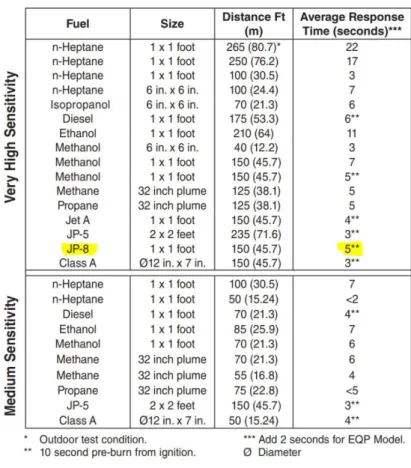
Table 26 -JP-8 Pool Fire Fuel Properties ... 65
1 | P a g e
Introduction
Figure 1 - Hanger During Construction
Building Background Information
2 | P a g e
3 | P a g e
Figure 3 – Facility Second Floor Plan
Applicable Codes
The governing document for building code compliance for this facility is Unified Facilities Criteria (UFC) 1-100-01 – DOD Building Code [1] which directs the design to follow a combination of International Code Council building codes, National Fire Protection Association standards, and other DOD Unified Facilities Criteria. The building was designed to meet the 2016 DOD Building Code, the relevant building and fire code references for life safety compliance for this report are as follows:
• UFC 1-200-01: DOD Building Code - 2016 [1]
• UFC 3-600-01: Fire Protection Engineering for Facilities - 2016 [2] • UFC 4-211-01: Aircraft Maintenance Hangers - 2017 [3]
4 | P a g e
The prescriptive code analysis is done based upon a combination of UFC standards, International
Building Code (IBC) [4], and NFPA 101 codes and standards. Prescriptive compliance was checked against the building non separated occupancies of S-1 and B. The building was evaluated for building
construction type IIB. The separations, fire ratings, egress component sizing and spacing, fire alarm, and fire suppression systems were all evaluated.
The building was also evaluated for a performance-based code compliance. The performance-based analysis is based around NFPA 101 [5] Chapter 5 compliance. The building was evaluated against typical occupancy-specific fires for the facility. The objective of the performance-based design is to evaluate life safety and proving that the available safe egress time (ASET) is greater than the required safe egress time (RSET) for the evaluated design fires.
The report evaluates the hangar spaces in the building for asset protection of the aircraft stored within rather than for safety of the occupants. The asset protection will be evaluated by determining the reaction of the alarm and suppression systems to a design fuel spill pool fire of JP-8 jet fuel. The result of this exercise will be to determine the time the aircraft is exposed to the pool fire and what size heat release rate the fire will grow to.
The performance-based design utilizes the computer programs Fire Dynamics Simulator (FDS) and Thunderhead Engineering Pathfinder for fire modeling and exit modeling, respectively. The FDS
simulation is utilized to estimate the ASET and the Pathfinder simulation to estimate the RSET. Excel will also be utilized to automate hand calculations for evaluating the pool fire scenario in the hangar. The next section will address the prescriptive analysis of the facility.
Prescriptive Analysis
The building has been evaluated for prescriptive code compliance relating to building construction, building arrangement, fire suppression, and fire alarm systems. The occupancy classification of each space determines the required compliance path. The report will evaluate each of the above categories in the sections that follow.
Occupancy Classification Analysis
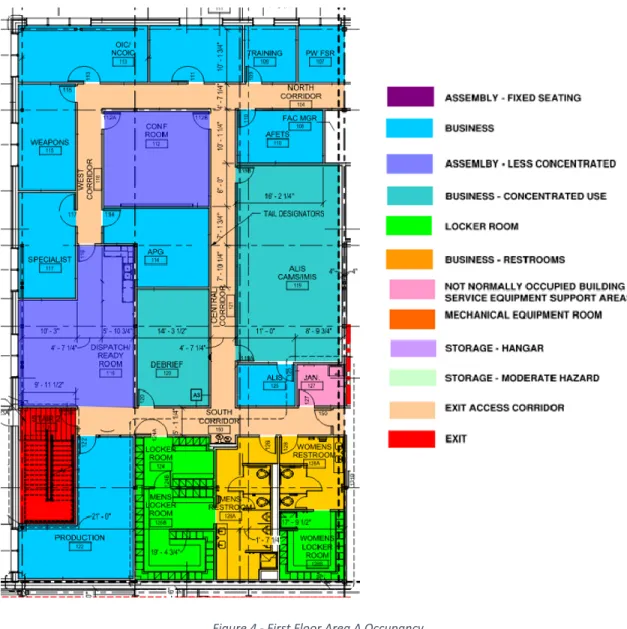
The required Occupancy Classification analysis will be based on the IBC code [4] and supplemented by the 2018 NFPA 101 [5]. The following figures (Figure 4 through Figure 9) show a color-coded breakdown of the building occupancy types based on a room by room analysis.
5 | P a g e
6 | P a g e
7 | P a g e
8 | P a g e
9 | P a g e
10 | P a g e
Figure 9 - Second Floor Area B Occupancy
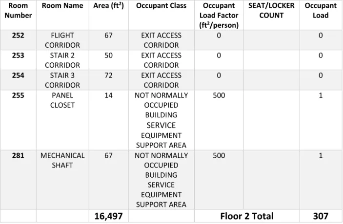
Occupant Load
The following Table 1 was developed to show the occupancy load of each space individually, the occupancy load factors are from Table 7.3.1.2 of the LSC [5].
Table 1 - Room by Room Occupancy
Room Number
Room Name Area (ft2) Occupant Class Occupant
Load Factor (ft2/person)
SEAT/LOCKER COUNT
Occupant Load
100 ENTRY 70 EXIT ACCESS
CORRIDOR
0 0
101 LOBBY 231 BUSINESS 150 2
11 | P a g e
Room Number
Room Name Area (ft2) Occupant Class Occupant
Load Factor (ft2/person)
SEAT/LOCKER COUNT
Occupant Load
103 COMM 154 NOT NORMALLY
OCCUPIED BUILDING SERVICE EQUIPMENT SUPPORT AREA
500 1
104 NORTH
CORRIDOR
317 EXIT ACCESS CORRIDOR
0 0
105 LM FSR 153 BUSINESS 150 2
106 LST/JPO 93 BUSINESS 150 1
107 PW FSR 153 BUSINESS 150 2
108 FAC MGR 93 BUSINESS 150 1
109 TRAINING 153 BUSINESS 150 2
110 AFETS 153 BUSINESS 150 2
111 ASST
OIC/ASST. SUPER
179 BUSINESS 150 2
112 CONF ROOM 341 ASSEMBLY - LESS
CONCENTRATED
15 23
113 OIC/NCOIC 251 BUSINESS 150 2
114 APG 235 BUSINESS 150 2
115 WEAPONS 207 BUSINESS 150 2
116 DISPATCH/RE ADY ROOM
529 ASSEMBLY - LESS CONCENTRATED
15 36
117 SPECIALIST 207 BUSINESS 150 2
118 WEST
CORRIDOR
112 EXIT ACCESS CORRIDOR
0 0
119 CAMS 710 BUSINESS -
CONCENTRATED USE
50 15
120 DEBRIEF 289 BUSINESS -
CONCENTRATED USE
50 6
121 CENTRAL
CORRIDOR
249 EXIT ACCESS CORRIDOR
0 0
122 PRODUCTION 377 BUSINESS 150 3
123 STAIR 2 227 EXIT 0 0
124 LOCKER
ROOM
95 LOCKER ROOM LOCKER
COUNT
16 16
125 OFFICE 80 BUSINESS 150 1
126A MENS
RESTROOM
268 BUSINESS -
RESTROOMS
12 | P a g e
Room Number
Room Name Area (ft2) Occupant Class Occupant
Load Factor (ft2/person)
SEAT/LOCKER COUNT
Occupant Load
126B MENS
LOCKER ROOM
164 LOCKER ROOM LOCKER
COUNT
34 34
127 JAN 67 NOT NORMALLY
OCCUPIED BUILDING SERVICE EQUIPMENT SUPPORT AREA
500 1
128A WOMENS
RESTROOM
160 BUSINESS -
RESTROOMS
150 2
128B WOMENS
LOCKER ROOM
141 LOCKER ROOM LOCKER
COUNT
19 19
129 SUPPORT - TOOL STORAGE
6971 STORAGE -
MODERATE HAZARD
500 14
130 HANGAR
CORRIDOR
83 EXIT ACCESS
CORRIDOR
0 0
131 HANGAR
ENTRY
107 EXIT ACCESS CORRIDOR
0 0
132 COLL
STORAGE
319 STORAGE -
MODERATE HAZARD
500 1
133 EQUIPMENT ACCOUNT
86 BUSINESS 150 1
134 FLIGHT
COMMAND
279 BUSINESS 150 2
135 COSO - STORAGE -
MODERATE HAZARD
500 -
136 PACK OUT - STORAGE -
MODERATE HAZARD
500 -
137 BATTERY
CORRIDOR
158 EXIT ACCESS CORRIDOR
0 0
138 BATTERY
CHARGE
142 STORAGE -
MODERATE HAZARD
500 1
139 BATTERY
STORAGE
102 STORAGE -
MODERATE HAZARD
500 1
13 | P a g e
Room Number
Room Name Area (ft2) Occupant Class Occupant
Load Factor (ft2/person)
SEAT/LOCKER COUNT
Occupant Load
141 HANGAR BAY 1
9601 STORAGE -
HANGAR
500 20
142 HANGAR BAY 2
9595 STORAGE -
HANGAR
500 20
143 HANGAR
STAIR 1
- STORAGE -
HANGAR
500 -
144 AVIONICS
WEST
459 MECHANICAL
EQUIPMENT ROOM
500 1
145 HANGAR
STAIR 2
- STORAGE -
HANGAR
500 -
146 AVIONICS
EAST
460 MECHANICAL
EQUIPMENT ROOM
500 1
147 FIRE 314 MECHANICAL
EQUIPMENT ROOM
500 1
148 MECH 767 MECHANICAL
EQUIPMENT ROOM
500 2
149 ELEC 337 NOT NORMALLY
OCCUPIED BUILDING SERVICE EQUIPMENT SUPPORT AREA
500 1
150 SOUTH
CORRIDOR
242 EXIT ACCESS CORRIDOR
0 0
36,852
Floor 1 Total
247
200 LOBBY 183 BUSINESS 150 2
201 OPS DESK 257 BUSINESS 150 2
202 STAIR 1 198 EXIT 0 0
203 DO 188 BUSINESS 150 2
204 COMM 131 NOT NORMALLY
OCCUPIED BUILDING SERVICE EQUIPMENT SUPPORT AREA
500 1
14 | P a g e
Room Number
Room Name Area (ft2) Occupant Class Occupant
Load Factor (ft2/person)
SEAT/LOCKER COUNT
Occupant Load
206 JAN 63 NOT NORMALLY
OCCUPIED BUILDING SERVICE EQUIPMENT SUPPORT AREA
500 1
207 FLIGHT
CMDR 4
99 BUSINESS 150 1
208 FLIGHT
CMDR 3
106 BUSINESS 150 1
209 FLIGHT
CMDR 2
107 BUSINESS 150 1
210 FLIGHT
CMDR 1
100 BUSINESS 150 1
211 TRAINING 273 BUSINESS -
CONCENTRATED USE
50 6
212 WOMENS
RESTROOM
197 BUSINESS -
RESTROOMS
150 2
213 STAN EVAL 329 BUSINESS 150 3
214 MENS
RESTROOM
257 BUSINESS -
RESTROOMS
150 2
215 HERITAGE
ROOM
850 ASSEMBLY - LESS CONCENTRATED
15 57
216 OPS LOCKER ROOM
1007 LOCKER ROOM LOCKER
COUNT
49 49
217 STAIR 2 227 EXIT 0 0
218 PFE MAINT 377 BUSINESS 150 3
219 PFE STORAGE 1007 STORAGE -
MODERATE HAZARD
500 3
219A PFE OFFICE 102 BUSINESS 150 1
220 MAN TRAP 125 EXIT ACCESS
CORRIDOR
0 0
221 MISSION
PLANNING
1449 BUSINESS - CONCENTRATED
USE
50 29
222 SECURITY 174 BUSINESS 150 2
223 MB 1 159 BUSINESS 150 2
224 ADMIN 279 BUSINESS 150 2
225 SERVER 601 NOT NORMALLY
OCCUPIED BUILDING SERVICE
15 | P a g e
Room Number
Room Name Area (ft2) Occupant Class Occupant
Load Factor (ft2/person)
SEAT/LOCKER COUNT
Occupant Load
EQUIPMENT SUPPORT AREA
226 SA-1 521 BUSINESS 150 4
227 MB 2 159 BUSINESS 150 2
228 MB 3 163 BUSINESS 150 2
229 MB 4 162 BUSINESS 150 2
230 MB 5 163 BUSINESS 150 2
231 WEAPONS 286 BUSINESS 150 2
232 PLANS 136 BUSINESS 150 1
233 MB 6 177 BUSINESS 150 2
234 COMM 114 NOT NORMALLY
OCCUPIED BUILDING SERVICE EQUIPMENT SUPPORT AREA
500 1
235 LARGE
MISSION BRIEFING
935 ASSEMBLY -
FIXED SEATING
SEAT COUNT
66 66
236 SARM CHIEF 126 BUSINESS 150 1
237 SARM 330 BUSINESS 150 3
238 SAFETY 157 BUSINESS 150 2
239 UDM 93 BUSINESS 150 1
240 COMMAND
SUPPORT
359 BUSINESS 150 3
241 CEM/SUPER 138 BUSINESS 150 1
242 SQUAD
COMM
153 BUSINESS 150 2
243 CONF ROOM 322 ASSEMBLY - LESS
CONCENTRATED
15 22
244 ADO 239 BUSINESS 150 2
245 OFFICE NS 240 BUSINESS 150 2
246 OPEN OFFICE 511 BUSINESS 150 4
247 STAIR 3 195 EXIT 0 0
248 EAST
CORRIDOR
270 EXIT ACCESS CORRIDOR
0 0
249 NE
CORRIDOR
237 EXIT ACCESS CORRIDOR
0 0
250 NW
CORRIDOR
547 EXIT ACCESS CORRIDOR
0 0
251 WEST
CORRIDOR
261 EXIT ACCESS CORRIDOR
16 | P a g e
Room Number
Room Name Area (ft2) Occupant Class Occupant
Load Factor (ft2/person)
SEAT/LOCKER COUNT
Occupant Load
252 FLIGHT
CORRIDOR
67 EXIT ACCESS
CORRIDOR
0 0
253 STAIR 2 CORRIDOR
50 EXIT ACCESS
CORRIDOR
0 0
254 STAIR 3 CORRIDOR
72 EXIT ACCESS
CORRIDOR
0 0
255 PANEL
CLOSET
14 NOT NORMALLY
OCCUPIED BUILDING
SERVICE
EQUIPMENT SUPPORT AREA
500 1
281 MECHANICAL SHAFT
67 NOT NORMALLY
OCCUPIED BUILDING SERVICE EQUIPMENT SUPPORT AREA
500 1
16,497
Floor 2 Total
307
Table 2 was developed to show the occupancy load of the whole building based on gross area:
Table 2 - Occupancy Based on Gross Area
Space Gross
Area (ft2)
Occupant Load
Total Occupants
Hangars 19,196 500 39
Storage 13,121 500 27
Floor 1 Business Use 3,395 100 34
Floor 1 Assembly Less Concentrated Use
870 (Net)
15 58
Floor 1 Total 158
Floor 2 Business Use 14,715 100 148
Floor 2 Assembly Less Concentrated Use
850 (Net)
15 57
Floor 2 Assembly Fixed Seating
935 (Net)
# Seats 66
17 | P a g e
The occupancy of the overall building can be evaluated based upon the gross area shown in Table 2 for the overall egress capacities. Each space should be evaluated against its maximum occupancy from Table 1 for the room specific egress sizing criteria.
With building occupancy determined the exit capacities can be analyzed based upon these numbers. The next section will determine building exit capacities and adequacy.
Exit Capacities and Adequacy
The exit capacities for each egress element are shown on the attached Occupancy and Exiting drawings in Appendix A.
Sizing of egress elements is done based upon NFPA 101 [5] Table 7.3.3.1. For this facilities occupancy stairs are required to provide 0.3 inches width per occupant, all other egress elements shall provide 0.2 inches width per occupant. Each of the stair and door components of the egress path are analyzed in the following figures (Figure 10 through Figure 16) to show the occupants served, width required, and width provided.
18 | P a g e
19 | P a g e
20 | P a g e
21 | P a g e
22 | P a g e
23 | P a g e
Figure 16 - 2nd Floor Area B Exit Capacity
All egress elements are adequately sized per the NFPA 101 [5] sizing criteria. The exit door and stair widths are adequate to serve the occupant loads based upon the total gross areas of the main use occupancies. The next section will evaluate whether the number of exits provided are prescriptively compliant.
Number of Exits Required
24 | P a g e
Table 3 - Number of Exits Required
Space # Exits
Provided
Occupants Exits
Required
Floor 1 8 247 2
Floor 2 3 307 2
Heritage Room 215
2 57 2
Large Mission Briefing 235
2 66 2
Arrangement of Exits
The arrangement of exits is shown in the attached Appendix B. Dead-end corridor, Travel distance and common path of travel are annotated on the drawings in Appendix B. The following tables break down the longest of each of the elements based upon the most restrictive occupancy served.
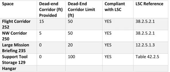
Dead-end Corridors
Regulations for Dead-end corridors for the major occupancies are regulated by the Life Safety Code [5]. The specific requirements are listed in Table 4 below. The LSC [5] references are from Chapter 12 for new Assembly, Chapter 38 for new Business and Chapter 42 for Storage.
Table 4 -Dead End Corridors
Space Dead-end
Corridor (ft) Provided
Dead-End Corridor Limit (ft)
Compliant with LSC
LSC Reference
Flight Corridor 252
15 50 YES 38.2.5.2.1
NW Corridor 250
5 50 YES 38.2.5.2.1
Large Mission Briefing 235
0 20 YES 12.2.5.1.3
Support Tool Storage 129
0 100 YES Table 42.2.5
Hangar
Travel Distance
Travel distance for the new assembly spaces is limited to 250’ as outlined in LSC [5] 12.2.6.2(1). Travel
distance for the new business space is limited to 300’ as outlined in 38.2.6.3. Travel distance for new industrial spaces is limited to 250 ft as outlined in Table 40.2.6.1. Travel distance for storage occupancy is limited to 400’ as outlined in Table 42.2.6. The attached drawings in Appendix B shows the
25 | P a g e
Table 5 - Travel Distance
Space Travel
Distance (ft) Provided
Travel Distance Limit (ft)
Compliant with LSC
LSC Reference
First Floor Business 107’ 300 YES 38.2.6.3
First Floor Storage 77’6” 400 YES Table
42.2.6
Hangar 91’11” 250 YES 40.2.6.1
Second Floor Business
142’1” 300 YES 38.2.6.3
Heritage Room 215 68’ 250 YES 12.2.6.2(1)
Large Mission Briefing 235
99’9” 250 YES 12.2.6.2(1)
Common Path of Travel
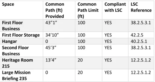
Common Path of Travel for the new assembly spaces is limited to 20’ as outlined in LSC [5] 12.2.5.1.2. Common Path of Travel distance for the new business space is limited to 100’ as outlined in 38.2.5.3.1. Common Path of Travel distance for new industrial spaces is limited to 100’ ft as outlined in Table 40.2.5.1. Common Path of Travel distance for storage occupancy is limited to 100’ as outlined in Table
42.2.5. The attached Appendix B shows the measurement of the Common Path of Travel distances. The analysis for travel distance will be based upon the worst-case length for each floor and unique
occupancy area. The following Table 6 summarizes compliance with 2015 LSC [5] travel distance limitations.
Table 6 - Common Path of Travel
Space Common
Path (ft) Provided
Common Path Limit (ft)
Compliant with LSC
LSC Reference
First Floor Business
43”1” 100 YES 38.2.5.3.1
First Floor Storage 34’10” 100 YES 42.2.5
Hangar 0 100 YES 40.2.5.1
Second Floor Business
45’3” 100 YES 38.2.5.3.1
Heritage Room 215
13’4” 20 YES 12.2.5.1.2
Large Mission Briefing 235
26 | P a g e
Remoteness of Means of Egress
Measurements for the remoteness of means of egress are located on the drawings in Appendix C. Regulations for remoteness of means of egress are in section 7.5.5.1.3.3 of the LSC [5] for buildings protected throughout by a sprinkler system. Table 7 summarizes the remoteness of spaces that require more than one exit.
Table 7 - Means of Egress Remoteness
Space Max
Diagonal Distance
1/3 Max Diagonal Distance
Distance Between Exits Provided
Compliant with LSC
LSC Reference
First Floor 199’11” 66 94’5” YES 7.5.5.1.3.3
Second Floor 199’3” 66 87’11” YES 7.5.5.1.3.3
Hangar Bay 1 150’7” 50 82’2” YES 7.5.5.1.3.3
Hangar Bay 2 150’7” 50 82’2” YES 7.5.5.1.3.3
Heritage Room 215
57’1” 19 37’10” YES 7.5.5.1.3.3
Large Mission Briefing 235
42 14 27’4” YES 7.5.5.1.3.3
Egress Component Analysis
Horizontal Exits
The building does not contain horizontal exits.
Exit Sign Placement
See Appendix D for Exit sign placement in accordance with UFC 3-600-01 [2] which requires compliance with NFPA 101 [5] Section 7.10.1.2.1 exits, other than the main exterior exit doors, shall be marked by a sign that is readily visible from any direction of exit access. Horizontal components of the egress path within an exit enclosure shall be marked by an exit or directional exit sign. Access to exits shall be marked by exit signs where the exit or way to reach the exit is not readily apparent to the occupants. Exits signs shall not be further apart than the rated distance of the sign or 100 feet, whichever is less. Signs shall be placed showing direction of travel in every location where the direction of travel to reach the nearest exit is not apparent.
The placement of the exit signs is in compliance with LSC [5] requirements.
Egress Component Summary
27 | P a g e
Building Construction Analysis
The building has been analyzed for construction features based upon the code of record criteria. The following sections summarize the construction feature requirements and the application of those requirements to the project building.
Fire Resistance Ratings
The corridors and lobbies are not required to be rated in an assembly occupancy based upon LSC [5] paragraph 12.3.6(2). The corridors are not required to be rated in a business occupancy based upon NFPA 101 [5] paragraph 38.3.6.1 (3). There are no specific corridors for the storage or industrial occupancies in the facility.
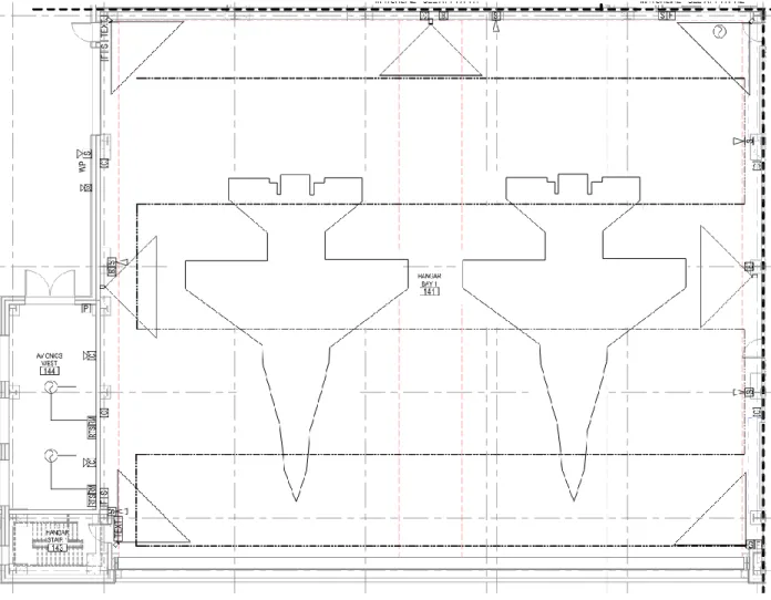
UFC 4-2101 [3] requires a 2-hour separation between different hangar bays. The UFC also requires a 1-hour separation between the hangar bay and the support areas (storage, offices).
28 | P a g e
Figure 17 - Fire Resistive Ratings
Interior Finish Requirements
The main building occupancy is business. The LSC [5] chapter 38 New Business Occupancies requirements for interior finish are governed by NFPA 101 [5] Paragraph 38.3.3.2 AND 38.3.3.3. As designed the Architectural design is in compliance with these requirements. The regulated finish requirements are outlined in Table 8.
Table 8 - Interior Finish
Element Rating Class Section Compliant with
LSC
Interior Wall A, B or C 38.3.3.2.1 YES
Interior Ceiling A, B or C 38.3.3.2.1 YES
Exit Enclosure Floor
29 | P a g e
Heights and Allowable Areas:
IBC [4] Table 504.3 determines the allowable building height above grade plane. Table 504.4 determines the allowable stories above grade plane. Table 506.2 determines the allowable area factor At for use in
determining the allowable area Aa. Table 9 summarizes the table values for the Hangar building that is
fully sprinklered.
Table 9 - Allowable Areas
Group Construction Type
# of Stories
Allowable Height
Sprinklered Allowable Area At
Nonsprinklered Allowable Area NS
S-1 II-B 3 75 70,000 ft2 17,500 ft2
B II-B 4 75 92,000 ft2 23,000 ft2
Section 506 is used to determine the allowable building area Aa. For the Hangar building we will utilize
section 506.2.4 for mixed-occupancy, multistory buildings in accordance with our nonseparated occupancy methodology as described in the section 508.3 discussion below. The area will be based around our most restrictive occupancy of S-1.
The allowable area will be determined based upon the following equation from the IBC [4]:
Aa= At + (NSxIf) Eq 1
Section 506.3 determines the frontage increase, If, for the building. The frontage increase is based upon
the following equation from the IBC [4]:
If = [F/P-0.25]W/30 Eq 2
W is determined by the public or open space around the building, limited to 30 ft maximum. For our building, the open space is greater than 30 ft, so W will be 30 for determination of If. The F/P is also
equal to 1 since the open area covers the full perimeter of the building.
If = [1-0.25]30/30 = 0.75 Eq 3
Aa = 70,000 ft2 + (17,500 ft2 x 0.75) = 83,125 ft2 Eq 4
The building area of 33,446 gross ft2 is less than the allowable building area, so a construction type of
II-B is allowable.
The building height as constructed is 58 feet tall. This is less than the allowed 75 ft as shown in Table 9.
Occupancy Separation
30 | P a g e
The allowable building area and height for the nonseparated spaces will be based upon the most restrictive of the mixed occupancies. In the case of the Hangar building, the S-1 occupancy is the most restrictive.
Fire Resistance Summary
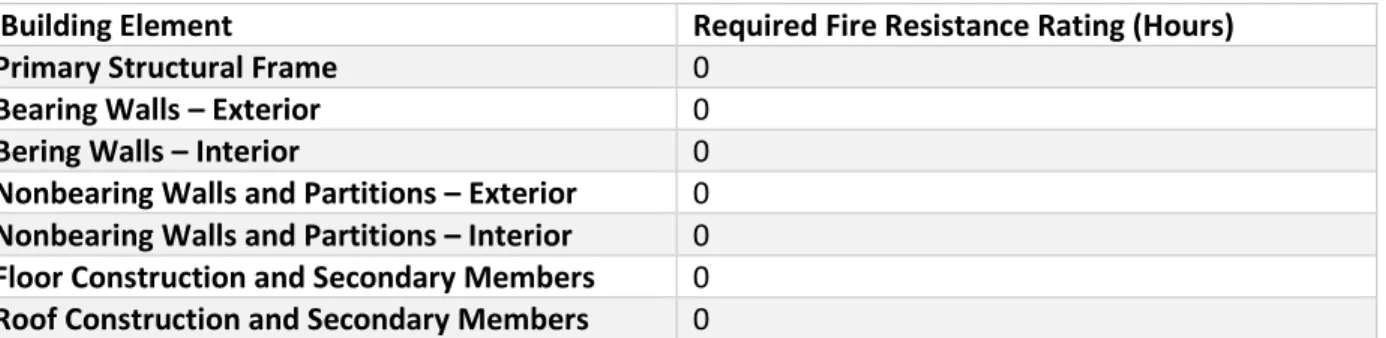
The fire resistance requirements are based upon Chapter 6 of the IBC [4].
IBC [4] Table 601 shows the requirements of fire resistive construction of a type II-B construction type. Table 10 of this report shows the required fire resistance ratings of the hangar facility.
Table 10 - Fire Resistance Ratings
Building Element Required Fire Resistance Rating (Hours)
Primary Structural Frame 0
Bearing Walls – Exterior 0
Bering Walls – Interior 0
Nonbearing Walls and Partitions – Exterior 0
Nonbearing Walls and Partitions – Interior 0
Floor Construction and Secondary Members 0
Roof Construction and Secondary Members 0
IBC [4] Table 602 is used to determine the exterior wall rating requirements based upon the separation distance. As previously noted the fire separation distance for the hangar facility is greater than 30 ft. Table 11 summarizes the exterior wall rating requirements for the hangar facility.
Table 11 - Exterior Wall Ratings
Fire Separation Distance (ft) Type of Construction Occupancy Group F-1, M, S-1
X≥30 All 0
Smoke Control Features
The building is provided with both passive and active smoke protection systems. The passive smoke protection systems were discussed in the fire resistance rating sections where the report has identified fire rated separations that are sealed such that they will also resist the passage of smoke.
The buildings active smoke protection comes in the form of air handler smoke detectors. The smoke detectors shutdown air handler operation when activated to eliminate the passage of smoke from one occupied space to another through the ventilation system. The smoke detectors are provided on the supply side ductwork of all air handlers 2,000 cfm or greater in capacity that also serve more than one occupied space.
31 | P a g e
The fire resistance requirements, allowable areas and heights and smoke control features were analyzed and found to be compliant with their code citations. The next section will analyze the fire alarm systems for their code compliance.
Fire Alarm System
Alarm System Type
The building is protected by an emergency communications system (ECS) – combination. The system consists of an emergency voice alarm communications system (EVACS) in combination with a building mass notification system (MNS). The system configuration includes-building fire emergency voice/alarm communication system for local fire alarm and an in-building MNS to provide in building alerts to building occupants. The MNS system is connected to a wide area MNS system in which post wide MNS communications can be broadcast to the building and building exterior. All occupied areas are provided with speakers to allow the voice fire alarm and MNS voice messages to be disseminated to the
occupants. The building exit doors are provided with text signs for MNS notification delivery. The system is set up to be a one way ECS system with only outgoing messages from the fire alarm control panel able to communicate. The system is also provided with a local microphone at the fire alarm/MNS panel to allow building wide emergency announcements to be provided in addition to onboard pre-recorded messages.
The building fire alarm system broadcasts to a proprietary supervising station system at the post fire department. The post fire department will be notified of any alarms, troubles, and supervisory signals from the system.
The hangar space has a high expansion foam generator system to provide suppression to the hanger bay in the event of a fire. The fire alarm system provides the releasing control with a releasing service fire alarm control unit (RSFACU) to initiate the foam system discharge.
The basis of design for the EVACS/MNS system is compliance with NFPA 72 [6] chapter 24 and UFC 4-021-01 [7] installation requirements.
The fire alarm control panel (FACP) and system evaluated will be based upon a Notifier NFS2-640
32 | P a g e
Figure 18 – Fire Room
Detection Devices
The building is provided with a combination of sprinkler and fire alarm detection devices. The fire sprinkler system consists of a wet pipe system to serve the office and tool storage areas of the building. The hangar bays are protected using a combination of a pre-action sprinkler system and a high
expansion foam system.
33 | P a g e
with manual release stations at each of the man exit ways out of the hangar. A manual foam stop station
is located at each exit from the hangars. The stop stations are of the “deadman” type requiring that the operator maintain pressure on the switch to operate the override to ensure that during normal
operation of the building the switch is not put into the stop position defeating the HEF system. The wet pipe sprinkler system is monitored with a flow switch that will activate the fire alarm upon sensing flow.
The building has a single ceiling photoelectric smoke detector monitoring the conditions at the fire alarm control panel as required by NFPA 72 [6] 10.4.4. The building HVAC system is also provided with photoelectric duct smoke detectors as required by NFPA 72 [6] 17.7.5.4.2 to shut down HVAC systems and provide a supervisory signal at the FACP and transmitted to the central station.
There are smoke detectors placed at the elevator doors to be utilized for elevator recall functions. There is a heat detector in conjunction with a smoke detector at the top of the elevator shaft to provide elevator recall functionality as well.
Manual pull stations at each exit pathway allow for manual activation of the fire alarm system within the building from occupants exiting.
Location, Spacing and Placement of Fire Detection Devices
The wet sprinkler systems risers are provided with water flow monitoring switches to provide an alarm signal after sprinkler operation. The water flow switch is provided with a time delay
The hangar IR cameras are spaced to cover the floor area under the aircraft such that all areas of the hangar are visible to at least three cameras as required by UFC 4-211-01 [3] paragraph 3-10.7.7.4. The line-type heat cable detector is installed on the hangar ceiling per the manufacturers listing in
accordance with NFPA 72 [6] 17.6.3.1.3.2 and 17.6.3.1.1. The spacing has been reduced based upon the ceiling height reduction requirements in table 17.6.3.5.1 to 0.34 times the listed spacing for a ceiling height of 30 ft. The minimum spacing as defined by 17.6.5.2 is 0.4 times the listed spacing. The listed spacing of the detector chosen is 30 ft, the minimum spacing is the defining dimension, the detector will
34 | P a g e
Figure 19 - Hangar Detection Layout
The ceiling photoelectric smoke detector monitoring the conditions at the fire alarm control panel will be installed as required by NFPA 72 [6] 10.4.4. The building HVAC system photoelectric smoke detectors are to be installed in ductwork serving units with over 2,000 cfm supply air.
35 | P a g e
Table 12 - Triple IR Detector Response Characteristics
Fire Alarm System Types and Requirements
The fire alarm system for the building is a proprietary supervising station type. The wiring for the signal line circuit (SLC), notification appliance circuit (NAC) and the MNS systems are to be Class B based around UFC 3-600-01 [2] standards. The pathway survivability is to be Level 1 based on non-rated wiring with a sprinklered building. The supervising station communicates with the building via a two-way radio frequency multiplex system.
36 | P a g e
Figure 20 - NFPA 72 Alarm Disposition
Supervisory signals within the building are to be handled based upon the following in Figure 21:
Figure 21 - NFPA 72 Supervisory Signal Actions
Trouble signals within the building are to be handled based upon the following in Figure 22:
37 | P a g e
38 | P a g e
39 | P a g e
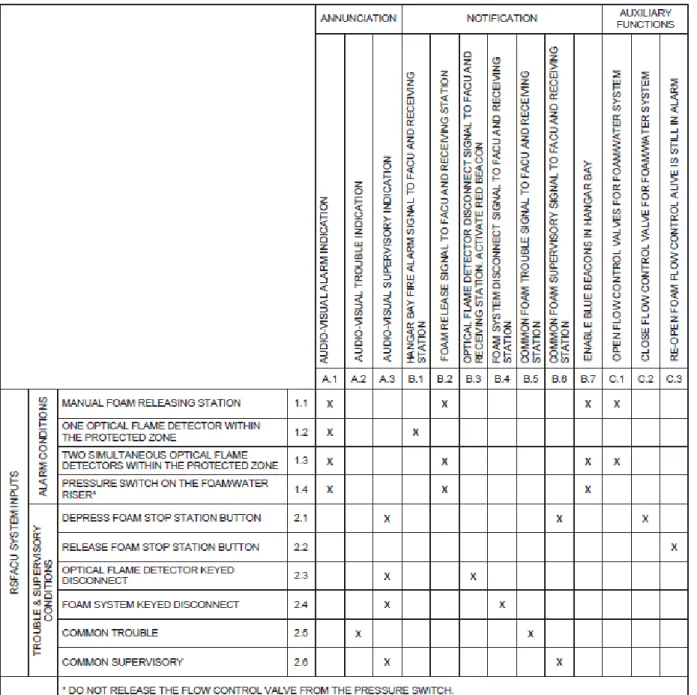
Figure 24: RSFACU Operational Matrix
Alarm Notification Appliances
40 | P a g e
Table 13 - Notification Appliances
Appliance Audible
Tone
Audible Voice
Visual Signal
Visual Text
Location Description
Combination Speaker Strobe
X X X - Wall Speaker and strobe
combination for MNS and EVACS notification
Ceiling Speaker X X - - Ceiling Speaker for MNS and EVACS
notification, large areas
Directional Speaker
X X - - Wall Speaker for MNS and EVACS
notification, large/loud areas
Weatherproof Horn/Strobe
X - X - Wall Exterior horn and visual
notification of EVACS and MNS
Text Sign - - - X Wall Visual text at exits for MNS
notification
Strobe - - X - Wall Visual notification for
EVACS/MNS
Blue Beacon - - X - Wall Hanger notification of Foam
Discharge
Red Beacon - - X - Wall Hangar notification of Flame
Detector activation
Omni Directional Speaker
- X - - Exterior Speaker for MNS and EVACS
notification
Analysis of Alarm Notification Appliances
The spacing and placement of the alarm notification appliances are based upon the requirements of NFPA 72 [6]. To show compliance the visible signaling devices have had their maximum room size overlaid onto the plans on the next sheet to show compliance with the spacing restrictions outlined in NFPA 72 [6] Table 18.5.5.4.1 (a) and (b).
41 | P a g e
Table 14 - NFPA 72 Visible Appliance Spacing
The audible notification is provided through a combination EVACS and MNS system that has speakers located throughout. The speakers are placed and sized to meet the intelligibility requirements of UFC 4-021-01 [7]. See the section on MNS system for further information.
Mass Notification Systems
The hangar building is equipped with a Mass Notification System (MNS) as required by the military UFCs for all buildings. The system is configured to be a one-way emergency communication system (ECS) that provided both emergency voice and alarm communications system (EVACS) and MNS operation. This is defined as an ECS-Combination system per NFPA 72 [6].
42 | P a g e
The speaker layout is based around making the audible notifications intelligible. UFC 4-021-01 [7] requires an intelligibility of 0.8 common intelligibility score (CIS) for the evaluated hangar facility. The UFC requires testing of intelligibility based on section 4-6.1.2. The language specific to the project building is as follows:
Verify intelligibility by measurement after installation.
Ensure that a CIS value greater than the required minimum value is provided in each area where building occupants typically could be found. The minimum required value for Air Force is 0.8 CIS, although
rounding is permitted such that a value of 0.75 may be rounded to 0.8.
Areas of the building provided with hard wall and ceiling surfaces (such as metal or concrete) that are found to cause excessive sound reflections may be permitted to have a CIS score less than the minimum required value if approved by the DOD installation, and if building occupants in these areas can
determine that a voice signal is being broadcast and they must walk no more than 10 m (33 ft) to find a location with at least the minimum required CIS value within the same area.
Areas of the building where occupants are not expected to be normally present are permitted to have a CIS score less than the minimum required value if personnel can determine that a voice signal is being broadcast and they must walk no more than 15 m (50 ft) to a location with at least the minimum required CIS value within the same area.
Measurements should be taken near the head level applicable for most personnel in the space under normal conditions (e.g., standing, sitting, sleeping, as appropriate).
The distance the occupant must walk to the location meeting the minimum required CIS value shall be measured on the floor or other walking surface as follows:
o Along the centerline of the natural path of travel, starting from any point subject to occupancy
with less than the minimum required CIS value.
o Curving around any corners or obstructions, with a 300-mm (12 in.) clearance therefrom.
o Terminating directly below the location where the minimum required CIS value has been
obtained.
Commercially available test instrumentation shall be used to measure intelligibility as specified by IEC 60849 and IEC 60268-16. The mean value of at least three readings shall be used to compute the intelligibility score at each test location. The audible appliances are tested to comply with this criteria during the fire alarm functional acceptance testing at the end of construction.
The speakers used in the MNS system must also meet audibility requirements of UFC 4-021-01 [7]. Section 6-5.3.1 requires that audible appliances provide a signal a minimum of 15 dBA above the average ambient sound level. The audible appliances are tested to comply with this criteria during the fire alarm functional acceptance testing at the end of construction.
Power Requirements for Fire Alarm and Communications Systems
43 | P a g e
Table 15 -Secondary Power Requirements
10.6.7 Secondary Power Supply
10.6.7.2 Capacity
10.6.7.2.1.7 The secondary power supply for in-building mass notification systems shall be capable of operating the system under quiescent load for a minimum of 24 hours and then shall be capable of operating the system during emergency conditions for a period of 15 minutes at maximum connected load.
10.6.7.2.1.1 Battery calculations shall include a minimum 20 percent safety margin above the calculated amp-hour capacity required.
44 | P a g e
Table 16 -Secondary Power Calculation
Commissioning and ITM of Alarm Systems
NFPA 72 [6] Chapter 14 governs the inspection, testing and maintenance (ITM) of the fire alarm system installed in our project building. Prior to ongoing ITM activities 14.2.5 requires that the record of completion documentation from Chapter 7 of the alarm system be completed after construction. These documents require the involvement of the Owner, Installing Contractor, Maintenance Contractor, and
Equipment Quantity
STANDBY CURRENT PER
UNIT (AMPS)
TOTAL STANDBY CURRENT PER
ITEM
ALARM CURRENT PER
UNIT (AMPS)
TOTAL ALARM CURRENT PER
ITEM
Smoke Detector 1 0.00023 0.00023 0.00033 0.00033
Duct Smoke Detector 5 0 0 0.012 0.06
Line Heat Detector 2 0.25 0.5 0.25 0.5
Monitor Module 35 0.005 0.175 0.005 0.175
Pull Station 10 0.000375 0.00375 0.005 0.05
Relay Module 12 0.00035 0.0042 0.0065 0.078
Releasing Control Module 2 0.0007 0.0014 0.009 0.018
Triple IR Detector 14 0.016 0.224 0.016 0.224
FACP 1 6 6 6 6
Relasing Panel 1 0.375 0.375 0.5 0.5
Ceiling Speaker 1W 9 0 0 0.0412 0.3708
Outdoor Horn/Strobe 6 0 0 0.228 1.368
Outdoor Speaker 11 0 0 0.0412 0.4532
Directional Speaker 18 0 0 0.0412 0.7416
Wall Speaker 5 0 0 0.0412 0.206
Text Sign 10 0 0 0.4 4
Wall Speaker Strobe (15cd) 9 0 0 0.101 0.909
Wall Speaker Strobe (30cd) 10 0 0 0.1246 1.246
Wall Speaker Strobe (75cd) 14 0 0 0.178 2.492
Red Beacon 2 0 0 0.005 0.01
Blue Beacon 6 0 0 0.005 0.03
Total Standby 7.28 Total Alarm 19.39
REQUIRED STANDBY TIME (HRS) NFPA 72-2002 4.4.1.5.3.1
TOTAL SYSTEM STANDBY CURRENT (AMPS)
REQUIRED STANDBY CAPACITY (AMP-HOURS)
REQUIRED ALARM TIME (HOURS) NFPA 72-2002 4.4.1.5.3.1
TOTAL SYSTEM ALARM CURRENT (AMPS)
REQUIRED ALARM
CAPACITY (AMP-HOURS)
24 7.28 174.81 0.25 19.39 4.85
REQUIRED STANDBY CAPACITY (AMP-HOURS)
REQUIRED ALARM
CAPACITY (AMP-HOURS)
TOTAL CAPACITY
(AMP-HOURS) SAFETY FACTOR
ADJUSTED BATTERY CAPACITY (AMP-HOURS)
45 | P a g e
testing organizations in commissioning of the newly installed system. The documents will then be submitted to the Authority Having Jurisdiction for their review.
Ongoing ITM is the responsibility of the Owner. The Owner may designate an authority for providing the ITM. ITM is performed based on the schedule indicated in NFPA 72 [6] Table 14.3.1 for visual inspection and 14.3.2 for testing. The ITM process shall verify function and operation of the system and any impairments/deficiencies found shall be corrected, or the owner’s designated representative needs to
be notified within 24 hours if it cannot be corrected.
The tables in NFPA 72 [6] cover an exhaustive list. Table 17 simplifies this for major systems installed in our project facility.
Table 17 – Fire Alarm ITM Intervals
System Component Inspection Testing Maintenance
All Equipment Annual Per Manufacturer
Functions - Annual Per Manufacturer
Fuses Annual Annual Per Manufacturer
Interfaced Equipment Annual Annual Per Manufacturer
Lamps and LEDs Annual Annual Per Manufacturer
Primary Power Supply Annual Annual Per Manufacturer
FACU Trouble Signals Semiannual Annual Per Manufacturer
Supervising station Alarms
Annual Annual Per Manufacturer
Voice Alarm Comm Equip
Semiannual Annual Per Manufacturer
Batteries Annual Per Manufacturer
Lead Acid Monthly Annual Per Manufacturer
Public Alarm reporting - Daily Per Manufacturer
Remote Annunciators Semiannual Annual Per Manufacturer
NAC Power Extender Annual Per Manufacturer
Initiating Devices
Duct Detectors Semiannual Annual Per Manufacturer
Sampling Tubes Annual Annual Per Manufacturer
Releasing Devices Semiannual Annual Per Manufacturer
Suppression Switches Semiannual Annual Per Manufacturer
Heat Detectors Semiannual Annual Per Manufacturer
Triple IR Detectors Quarterly Semiannual Per Manufacturer
Smoke Detectors Semiannual Annual Per Manufacturer
Fire Alarm Control Interface
Semiannual Per Manufacturer
Notification
Audible appliances Semiannual Annual Per Manufacturer
Text notification Semiannual Annual Per Manufacturer
Visible Appliance Semiannual Annual Per Manufacturer
Supervising Station Alarm
Signal Receipt Daily Monthly Per Manufacturer
46 | P a g e
System Component Inspection Testing Maintenance
Mass Notification System
Fuses Annual Annual Per Manufacturer
Interfaces Annual Annual Per Manufacturer
Lamps/LEDs Annual Annual Per Manufacturer
Primary Power Annual Annual Per Manufacturer
Batteries Annual Annual Per Manufacturer
Initiating devices Annual Annual Per Manufacturer
Notification appliances Annual Annual Per Manufacturer
Antenna Annual Annual Per Manufacturer
Transceivers Annual Annual Per Manufacturer
The alarm system as designed is prescriptively compliant with the codes of record for the facility. In the next section the fire suppression system will be analyzed for prescriptive compliance.
Fire Suppression
System Description
The hangar facility is provided with a wet pipe sprinkler system to serve the office and tool storage portion of the building. The aircraft hangars are protected by a combination of high expansion foam and a preaction sprinkler system. The building is provided with fire water from an adjacent building that has a fire pump to provide for the pressure requirements of high expansion foam generators located just below the roof in the hangar.
Building Occupancy Classification
NFPA 13 [8] occupancy classification for sprinkler system sizing will be based upon the function of the spaces within the building. Table 18 summarizes the unique occupancies related to sprinkler hazard.
Table 18 - Sprinkler Occupancy Classification
Space NFPA 13 Occupancy Classification
Office (General office and accessory spaces) Light Hazard
Storage Ordinary Hazard
Mechanical Rooms Ordinary Hazard
Electrical Rooms Ordinary Hazard
Fire Rooms Ordinary Hazard
Tool Storage Ordinary Hazard
Battery Storage Ordinary Hazard
Battery Charge Ordinary Hazard
Hangar Hangar (UFC 4-211-01 governed)
Sprinkler Demand
47 | P a g e
preaction system demand is based upon UFC 4-211-01 [3] requirements in paragraph 3-6.15.1. Table 19 summarizes the required sprinkler systems in the facility.
Table 19 - Sprinkler Density/Area Demand
Space UFC Required Sprinkler Demand
Light Hazard 0.1 gpm/ft2 over 1,500 Square Feet
Ordinary Hazard 0.2 gpm/ft2 over 2,500 Square Feet
Hangar Preaction 0.2 gpm/ft2 over 5,000 Square Feet
High Expansion Foam Demand
The demand for the high expansion foam system is based upon the requirements in UFC 4-211-01 [3] Section 3-6.18.1. The demand calculation is based around the UFC requirements to provide coverage of 90% of the housed aircrafts silhouette within 1 minute, and to provide 3.2 ft (1m) of foam depth in the entire hangar within 4 minutes. To calculate the foam discharge rate, the design must also include a foam break down rate based upon the preaction sprinkler system operating simultaneously and include a foam shrinkage compensation value. The UFC calculation for foam discharge rate is in equation 5 and provides a CFM quantity of foam flow. The flow of fire water required to support the required foam flow is based upon the project specified 2% concentrate solution. The flow rate in gpm is based upon the manufacture specified performance of the foam generator equipment. The project specified Ansul Jet-X 27 and Jet-X 2% high expansion foam solution will be utilized for the flow rate calculations.
𝑅 = ([𝑉
𝑇] + 𝑅𝑆) × 𝐶𝑁× 𝐶𝐿
Eq 5
48 | P a g e
Table 20 – High Expansion Foam Discharge Rate
Table 21 - High Expansion Foam Water Flow
Area of aircraft servicing area L x W = A = 9540 ft²
Depth of Submergence D = 3.20 ft per UFC 4-211-01, 3-6.17.1
Submergence Volume A x D = V = 30528 ft³
Submergence Time T = 4.0 minutes per UFC 4-211-01, 3-6.17.1
Sprinkler Design Area As = 5000 ft² No Increase for Sloped Ceiling per
UFC 4-211-01, 3-6.15.1
Sprinkler Design Density Ds = 0.20 gpm/ft²
Sprinkler imbalance / overflow
factor If = 32%
Estimated maximum total discharge
from sprinklers As x Ds x If = Q = 1320 gpm
Foam break down from sprinkler
discharge S = 10 gpm x ft³/min
Rate of foam breakdown by
sprinklers S x Q = Rs = 13200 ft³/min
Compensation for normal foam
shrinkage Cn = 1.15 per UFC 4-211-01, 3-6.18.1
Compensation for loss of foam due to leakage around door and windows
Cl = 2.0 per UFC 4-211-01, 3-6.18.1
([V/T] + Rs) x Cn x Cl ) = R = 47913.6 CFM
HIGH EXPANSION FOAM MINIMUM REQUIRED RATE OF DISCHARGE
Volume put out by an Ansul Jet-X 27
Generator at 53 PSI Vf = 24365.0 CFM
Solution Flow Rate of a Jet-X 27
Generator at 53 PSI Qf = 208 gpm
Number of generators required: N = 1.97 Generators
Number of Generators provided: N = 2 Generators
Approximate Flow Rate with all
generators flowing N x Qf = Q = 499 gpm 20% overflow included
Time to reach 4 times the
submergence volume (4 x V) / (Vf x N) = Ts = 2.5 minutes
Required foam solution required to
reach 4-times submergence volume Ts x N x Qf = Q1 = 1041.4 gallons Required foam solution to last 15
minutes 15 min x N x Qf = Q2 = 6234.0 gallons
Recommended Proportioning ratio E = 2.00%
Required foam concentrate storage required based on the worst case condition of 15 minutes
Q2 x E = Qc = 124.7 gallons Minimum required on-site
concentrate storage + 30% safety factor
Qc = 162.1 gallons
30% safety factor is per UFC 4-211-01, 3-6.11.3 (not required per NFPA 409)
FOAM GENERATOR GPM FLOW REQUIREMENT
49 | P a g e
General Sprinkler Information
The wet pipe sprinkler systems in the building are required by the project specifications to provide quick response pendant, upright, or sidewall heads with quick response elements and a 1/2 inch orifice. The quick response correlated to an RTI value of less than 50 (m-s)1/2 with an activation temperature of
175°F.
The preaction sprinkler systems in the building are required by specifications to provide a quick response pendant or upright sprinkler with 1/2 inch orifice. Due to the open structure of the hangar where the preaction is utilized the upright sprinkler is what is to be installed. The quick response correlated to an RTI value of less than 50 (m-s)1/2 with an activation temperature of 170°F.
High Expansion Foam System Information
50 | P a g e
Figure 25 – Fire Room Fire Suppression Layout
Fire Riser Information
51 | P a g e
water flow detection device and control valve. The two hangars are each served by a preaction system riser and a deluge valve high expansion foam riser with their own dedicated foam concentrate tank. The system is headered and served by a check valve, basket strainer, and a surge tank. The header will also be served by a fire department connection that will also be provide with a check valve.
Water Supply Information
The building is served by a fire water pump located in an adjacent facility. The fire pump is fed from a street water supply at 66 psi static, 20 psi residual with 2,400 gpm flowing. The fire pump is rated at 1,500 gpm at 160 psi. The fire pump is provided with a pressure regulating valve that is set to 160 psi discharge.
Hydraulic Calculation
The system hydraulic calculation was conducted in accordance with NFPA #13 Chapter 23 and utilizing the Hazen-Williams formula. The remote zone for this building is in the West hangar space and requires flowing of the full high expansion foam flow and the preaction system over the UFC required 5,000 remote square feet. The remote zone is shown in Figure 26.
52 | P a g e
Figure 26 show the remote preaction heads over the 5,000 square feet and the two high expansion foam generators serving the hangar.
The hydraulic calculation shows that the system demands are at the Point of Connection to Street Main are:
• Flow - 2,218.3 gpm at 10.1 psi.
Figure 27 shows the hydraulic demand graph of the fire system at the street source that feeds the fire pump. The water source can provide the demand flow for the remote zone in the hangar facility.
Figure 27 - Hydraulic Demand at Street Connection
The complete hydraulic calculation is presented in Appendix E.
Inspection Testing and Maintenance
Inspection, testing and maintenance (ITM) of NFPA 13 [8] system is governed by chapter 27 of NFPA 13 [8]. Chapter 27 references providing ITM based on NFPA 25 [9]. The following Table 22 represents a complete list of components to be ITM’d for this project based upon NFPA 25 [9].
Table 22 - General Fire Suppression ITM
System Component Inspection Testing Maintenance
Water Main Annually 5 Year Flow Test -
Main Drain - Annually -
Control Valves Monthly - -
53 | P a g e
System Component Inspection Testing Maintenance
Fire Department Connection
Visual Quarterly, Internal Annually
- Per Manufacturer
Gauges Quarterly 5 years -
Hanger/braces/supports Annually - -
Hydraulic Design Information Sign
Annually - -
Information Signs Annually - -
Internal Piping Condition
5 years - -
Pipe and Fittings Annually - -
Sprinklers (Fast Response)
Annually At 20 years and every 10 years thereafter
-
Sprinklers (Spare) Annually -
Supervisory Signal Devices
Annually Semiannually -
System Valves Quarterly - -
Valve Supervisory Signal Devices
Quarterly - -
Water Flow Alarm Devices (vane and pressure type switch)
Quarterly Semiannually -
Low Point Drains - - -
Inspection, Testing and Maintenance per NFPA 13 [8] paragraph 27.1 is the responsibility of the building Owner. They may hire a contractor to fulfil the requirement, but the Owner is the final responsible party to manage the ITM and any corrections required to be completed based upon inspections. NFPA 25 [9] Chapter 15 covers the process for handling impairments to the sprinkler system. The Owner or
designated representative shall be the impairment coordinator. Any system found to be impaired due to inspection, testing or maintenance shall be tagged out and Chapter 15 notification procedures must be followed. It is the impairment coordinators responsibility to get the system back into compliant
operating condition.
The fire suppression system is prescriptively compliant with the codes of record.