1. SECURITY TOOLS ANALYSIS IN LOCAL AREA NETWORKS (ACCESS CONTROL LIST)
1.1 Purpose of work
Configuration of the network fragment using network equipment. Setting access control lists on a switch. As filtering criteria used MAC- addresses and IP-addresses.
1.2 Background. Brief description of the safety provisions in local area networks
1.2.1 Access control lists (ACL)
Access Control List are the means of filtering data streams without loss of performance, as checking the contents of data packets is performed at the hardware level. Administrator can restrict types of applications approved for use on the network, control user access to the network and identifies the device to which they can be connect using the filtering of data streams. ACL also can be used to determine the policies QoS, by classifying traffic and redefining its priority.
ACLs are composed of Access Profile and Rules. Access profiles define the types of filtering criteria which must be verified in a data packet (MAC-address, IP-address, port number, VLAN, etc.), the rules specified directly the values of their parameters. Each profile may consist of a plurality of rules.
1.3 Methodical instructions and work order
Laboratory model description
A fragment of a telecommunication network consists of a switch, which is connected to 3 workstations and Internet gateway (see. Table 1.1).
Table 1.1
Equipment (on one work place):
Switch DЕS-3200-18 or DGS-3200-10 1 unit
Work station 3 unit
Console cable 1 unit
Ethernet cable 3 unit
1.3.1 Configuration users access restriction to the Internet than based on MAC-address
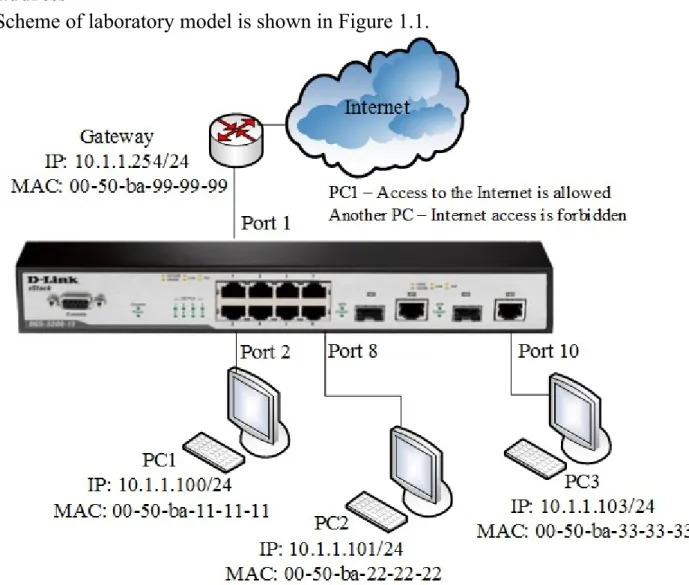
Scheme of laboratory model is shown in Figure 1.1.
Figure 1.1 – Network model for laboratory work
Task
Allow PC1 and PC2 users Internet access; the other users are deny. Users identified by MAC addresses of their computers.
Rules: Rule 1:
If the destination MAC address = Internet gateway MAC address and sourse MAC address = PC1 MAC address - permit;
If the destination MAC address = Internet gateway MAC address and sourse MAC address = PC2 MAC address - permit;
Rule 2:
If the destination MAC address = Internet gateway MAC address - deny; Rule 3:
Otherwise, the default to allow access all nodes.
Connect to the switch 1. Open Terminal
2. In Terminal Interface enter: minicom –s Choose Serial setup
Enter A dev/ttyS0 EC (bit rate 9600)F (No) Exit: Using command
reset config
Before performing the laboratory exercises necessary to replace these commands in the MAC address to the real MAC address of the workstation and the Internet gateway.
Rule 1
Create an access profile 10:
create access_profile ethernet source_mac FF-FF-FF-FF-FF-FF destination_mac FF-FF-FF-FF-FF-FF-FF-FF-FF-FF-FF-FF profile_id 10
Create a rule for profile 10 that allowing access to PC1 which connected to port 2, to Internet:
config access_profile profile_id 10 add access_id 11 ethernet source_mac 50-ba-11-11-11 destination_mac 00-50-ba-99-99-99 port 2 permit
Create a rule for profile 10 that allowing access to PC1 which connected to port 8, to Internet:
config access_profile profile_id 10 add access_id 12 ethernet source_mac 50-ba-22-22-22 destination_mac 00-50-ba-99-99-99 port 8 permit
Rule 2
Create access profile 20:
create access_profile ethernet destination_mac FF-FF-FF-FF-FF-FF profile_id 20
Create a rule for profile 20, that deny access to other users on the Internet: config access_profile profile_id 20 add access_id 21 ethernet destination_mac 00-50-ba-99-99-99 port 1-10 deny
Note: The new rule would prohibit passing frames containing the destination MAC address equal to the MAC address of an Internet gateway to all switch ports. If this rule must be applied to one of the ports in the configuration indicates a specific port that is connected to the station, the traffic that you want to block.
Execute by default
Check the created profiles ACL: show access_profile
1. Connect the station PC1 and PC2, as shown in Figure 1.1. Test the connection to the Internet gateway using command ping.
2. Connect another workstation or connect PC1 and PC2 to other switch ports and then try to access the Internet gateway.
3. Remove the rule from the access profile (for example, to disable the Internet from PC2):
config access_profile profile_id 10 delete access_id 12
4. Remove ACL the profile (for example, allows Internet access stations PC1 and PC2):
delete access_profile profile_id 10
1.3.2 Configuration of user’s access restriction to the Internet by IP-addresses
Figure 1.2 – Network model for laboratory work
Task
Permit the Internet access to users with IP-addresses from 10.1.1.1/24 to 10.1.1.63/24. Other users of the network 10.1.1.0/24, with addresses outside the permitted range, access to the Internet is deny.
Rules: Rule 1:
If the source IP-address = IP-addresses from the range: 10.1.1.1 - 10.1.1.63 (subnet 10.1.1.1/26) - permit;
Rule 2:
If destination MAC address= The Internet gateway MAC address - deny; Rule 3:
Otherwise, default allow access by everyone nodes.
Before executing the task, remove the last profile from previous task: delete access_profile profile_id 20
Make sure that no more profiles on the switch: show access_profile
Rule 1.
Create access profile number 10, allowing access to the subnet 10.1.1.0/26 (nodes 1 to 63):
create access_profile ip source_ip_mask
255.255.255.192 profile_id 10 Create a rule for access profile 10:
config access_profile profile_id 10 add access_id 11 ip source_ip 10.1.1.0 port 1-10 permit
Note: The new rule permits traffic to pass IP-subnet 10.1.1.0/26 to all switch ports. If this rule must be applied to one of the ports in the configuration indicates a specific port that is connected to the station, whose traffic should be permitted.
Rule 2
Create access profile 40:
create access_profile ethernet destination_mac FF-FF-FF-FF-FF-FF profile_id 40
1. Connect the equipment according with the scheme shown in Figure 1.2. Create a rule for access profile 40 that deny other stations connected to the Internet gateway:
config access_profile profile_id 40 add access_id 41 ethernet destination_mac 00-50-ba-99-99-99 port 1-10 deny
Rule 3
Permit all another: Execute by default
Check the created profiles: show access_profile
2. Connect workstations PC1 (address in the range 10.1.1.1-63/24) and PC2 (address in the range 10.1.1.64-253/24) to the switch. Test the connection to the ping Internet gateway
ping 10.1.1.254
3. Remove ACL profile (for example, profile 10). delete access_profile profile_id 10
Test the connection to the Internet gateway using ping command ping 10.1.1.254
1.4 Report content
Report on the implementation of laboratory work should include the following items: 1. Subject and purpose of the laboratory work
2. Block diagram of the network with the designation of ports, IP address, network mask interface of workstation and switch.
3. Order of the laboratory work performance (sequence of input commands with the relevant explanations). Graphic results of the commands.