Carrier Frequency Synchronization in OFDM-Downlink LTE Systems
Patteti Krishna1, Tipparthi Anil Kumar2, Kalithkar Kishan Rao3
1
Department of Electronics & Communication Engineering SVSIT, Warangal, AP, India
2
Department of Electronics & Communication Engineering SR Engineering College, Warangal, AP, India
3
Department of Electronics &Communication Engineering Vaagdevi College of Engineering
Warangal, AP, India
kpatteti@gmail.com, tvakumar2000@yahoomail.co.in, prof_kkr@rediffmail.com
ABSTRACT: Higher the data rates and spectrum efficiency of wireless mobile communications have been significantly improved over the last decade, such as 3GPP Long-Term Evolution (LTE) and terrestrial digital TV broadcasting which are sophisticatedly developed using OFDM. Orthogonal frequency division multiplexing (OFDM) is a modulation technique that achieves high data rates, increased bandwidth efficiency and robustness in multipath environments. However, OFDM has some disadvantages, such as sensitivity to channel fading, large peak to average ratio and sensitivity to frequency offset. The latter causes inter carrier interference (ICI) and a reduction in the amplitude of the desired subcarrier which results in loss of orthogonality. In this paper, the effects of frequency offset are studied in terms of loss of orthogonality. The main goals of this paper is to understand the effects of frequency offset on OFDM systems and to present frequency offset estimation techniques so that we can correct for their effects. The performance of each technique is compared under various conditions. The performance of the estimators is presented in terms of the mean square error (MSE) and Signals to noise ratio (SNR).
In this paper, we investigate carrier frequency synchronization in the downlink of 3GPP Long Term Evolution (LTE). A complete carrier frequency offset estimation and compensation scheme based on standardized synchronization signals and reference symbols is presented. The estimation performance in terms of mean square error is derived analytically and compared to simulation results.
Keywords: 3GPP-LTE, ICI, CFO, OFDM
Received: 12 March 2014, Revised 18 June 2014, Accepted 28 June 2014
© 2014 DLINE. All Rights Reserved 1. Introduction
of OFDMA is its vulnerability to Carrier Frequency Offset (CFO).Given a carrier frequency of 2.5 GHz, a typical frequency drift of 10ppm (10 × 106) of the local oscillator results in an offset of 25 kHz. In LTE, which employs a fixed subcarrier spacing of 15 kHz, such an offset corresponds to 1.67 subcarrier spacing. Synchronization for general OFDM systems has been investigated for example in [2–8]. The basic idea in these publications is to split the CFO into a Fractional Frequency Offset (FFO), an Integer Frequency Offset (IFO), and a Residual Frequency Offset (RFO), which can be estimated individually. In [2–4], a Cyclic Prefix (CP) based FFO estimator has been presented and the Cramer-Rao lower bound of this estimator has been derived in [8]. In order to expand the estimation range, an IFO estimator based on the maximum likelihood principle has been derived in [5]. The impact of RFO as well as RFO compensation schemes were investigated in [4, 6, 7]. Specifically for LTE, a synchronization concept was presented in [9]. However, the performance was only evaluated in terms of simulated Mean Squared Error (MSE). In this work, we present a entire chain of carrier frequency offset estimation blocks based on the standardized synchronization signals and reference symbols of LTE. Furthermore, we derive analytic expressions for the MSE of the CFO estimators. The paper is organized as follows. In Section II, the synchronization and reference signals of LTE are described. Section III explains our system model and the impact of CFO on an OFDM system. Results analysis is explain in Section IV. Finally we draw our conclusions in Section V.
2. Synchronisation and Reference Signals in LTE
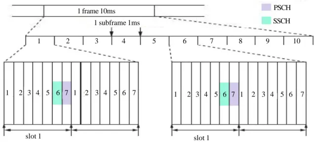
A radio frames in an LTE downlink transmission have a duration of Tframe = 10 ms.Each frame consists of 10 sub frames of equal length. Each sub frame contains two consecutive slots of time duration Tslot = 0.5 ms.The smallest scheduling unit is called one resource block which is a timefrequency grid of 12 subcarriers over Ns = 7 OFDM symbols for the normal CP length and Ns = 6 for the extended CP length. In the LTE downlink two kinds of signals can be utilized for synchronization at the receiver. Firstly, the dedicated synchronization signals, and secondly the cellspecific reference symbols.
2.1 Downlink Synchronization Signals
The LTE standard defines two synchronization signals, namely the primary (PSCH) and the secondary (SSCH). In FDD mode, these signals are located on the 62 subcarriers symmetrically arranged around the DC-carrier in the first slot in the sixth and seventh OFDM symbols of the first and the sixth sub frames, as shown in Figure 1.
Figure 1. Synchronization signals in LTE FDD downlink
Downlink synchronization for OFDM-based communication and broadcasting systems can be either preamble-based or pilot-based. The cellular system requires a process of cell searching in addition to synchronization and channel estimation. After initial synchronization, MS searches for the target BS with the best link connection among adjacent BSs, and continues to search for the possibility of handover. Depending on the standards in the cellular systems, slightly different terminologies are used for cell searching and downlink synchronization: preamble in PSS (Primary Synchronization Signal) and SSS (Secondary Synchronization Signal) in 3GPP LTE systems.
slot 1 slot 1
1 2 3 4 5 6 7 8 9 10
1 2 3 4 5 6 7 1 2 3 4 5 6 7 1 2 3 4 5 6 7 1 2 3 4 5 6 7 1 subframe 1ms
1 frame 10ms PSCH
3. Carrier Frequency Offset in OFDM
The baseband transmit signal is converted up to the pass band by a carrier modulation and then, converted down to the baseband by using a local carrier signal of the same carrier frequency at the receiver. In general, there are two types of distortion associated with the carrier signal. One is the phase noise due to the instability of carrier signal generators used at the transmitter and receiver, which can be modelled as a zero-mean Wiener random process. The other is the carrier frequency offset (CFO) caused by Doppler frequency shift fd . Let foffset denote their difference (i.e., foffset = fc− fc’). Meanwhile, Doppler frequency fd is determined by the carrier frequency fc and the velocity v of the terminal (receiver) as fd = v. fc
c
∆ f the speed of light, let us define the normalized CFO as a ratio of the CFO to subcarrier spacing ∆f, shown as ε =
, where c is the
of ε exists between transmitter and receiver, without any phase noise. The time-domain received signal can be written as foffset
. CFO
(1)Where X is the transmitted signal, H is channel matrix and additive white gaussian noise Z. yl [n] =1
N
Σ
N − 1
k = 0 H [k] Xl [l] e
j2π (k + ε) n / N
+ zl [n]
Figure 2. Effect of integer CFO on the received signal
If two identical training symbols are transmitted consecutively, the corresponding signals with CFO of are related with each other as follows:
ε =21π
Σ
k = 0N − 1y2 [n] = y1 [n] ej2πNε ↔ Y2 [k] = Y1 [k] ej2πε The CFO estimated as
tan−1⎧
⎩
⎨ in [[Y1 [k]. Y1 [k]]]
*
[Y1* [k]. Y1 [k]]
Although the range of CFO estimated by Equation (3) is π 2π |ε | ≤ = 1
2
zero value and then, averaged over the subcarriers. Note that this particular CFO estimation technique requires a special period, usually known as a preamble period, in which the consecutive training symbols are provided for facilitating the computation in Equation (3). In other words, it is only applicable during the preamble period, for which data symbols cannot be transmitted.
4. Results Analysis
The degradation of the SNR, Dfreq, caused by the frequency off-set, is approximated as Dfreq ≅ (π∆f T)2.
. Equation (3) is applied to the subcarriers with
non-Eb No
, where ∆f is the Xl [0]
Xl [1] Xl [2]
Xl [N − 2] Xl [N − 1]
Xl [N − 2] Xl [N − 1] Xl [0] Xl [1] Xl [2]
Xl [0 εi] Xl [1 −εi] Xl [2 − εi]
Xl [N − 2 − εi] Xl [N − 1 −εi] Xl [N − 2]
Xl [N − 1]
ej2πε l (N −2) / N
ej2πε l (N −2) / N
Xl [0] Xl [1] Xl [2]
ej2πε l 0 / N
ej2πε l 1 / N
ej2πε l 2 / N
N-point FFT (Receiver) N-point IFFT (Transmitter)
xej2πε l 2/ N
the frequency offset, T is the symbol duration in seconds, is the energy per bit of the OFDM signal and is the one-sided noise power spectrum density (PSD). The frequency offset has an effect like noise and it degrades the signal-to-noise ratio (SNR), where SNR is the
values, the degradation is less than for bigger SNR values as shown in Figure 6. The mean squared CFO estimation errors decrease as the SNR of received signal increases (see Figure 5.17). Performances of estimation techniques vary depending on the number of samples in CP, the number of samples in preamble, and the number of pilot tones, used for CFO estimation.
Figure 4. MSE of CFO estimation techniques
Figure 3. SNR degradation of frequency offset for differentEb values (5, 10, 15, 17 dB) No
5. Conclusion
In this paper, a CFO compensation scheme for 3GPP LTE is presented and evaluated. Simulation results show that the 0 5 10 15 20 25 30
SNR [dB] CFO Estimation 10−2
10−3
10−4
10−5
10−6
10−7
CP-based techniques Moose
Classen
MSE
10−7 10−8 10−9 10−10 10−11
10−12 10−13
10−14
10−15
0 0.05 0.1 0.15 0.2 0.25 0.3 0.35 0.4 0.45 0.5
15 db 17 db
10 db 5 db
SNR degradation (Dfreq) in dB
Eb
presented three stage scheme is sufficient to compensate even relatively large CFOs in slow fading scenarios. Compared to perfect synchronization, the performance loss is hardly noticeable. Since the synchronization and reference signals in the standard are not dedicated for carrier frequency synchronization but mainly used for cell search and channel estimation.
References
[1] 3GPP. (2008). Technical specification group radio access network; (E-UTRA) and (E-UTRAN); overall description; stage 2, Tech. Rep.
[2] Richard Van Nee, Ramjee Prasad. (2000). OFDM for Wireless Multimedia Communications, The Artech House Universal Personal Communications, Norwood, MA.
[3] Manolakis, K., Gutierrez Estevez, D. M., Jungnickel, V., Xu, W., Drewes, C. (2009). A closed concept for synchronization and cell search in 3GPP LTE systems, In: Proc. IEEE Wireless Communication and Networking Conference (WCNC), Budapest, Hungary.
[4] Speth, M., Fechtel, S., Fock, G., Heyr. (2001). Optimum receiver design for OFDM-based broadband transmission. II. a case study, IEEE Transactions on Communications, 49, p. 571–578, April.
[5] Toumpakaris, D., Lee, J., Lou, H. (2009). Estimation of integer carrier frequency offset in OFDM systems based on the maximum likelihood principle, IEEE Transactions on Broadcasting, 55, p. 95–108, March.