AUSTRALIAN JOURNAL OF BASIC AND
APPLIED SCIENCES
ISSN:1991-8178 EISSN: 2309-8414 Journal home page: www.ajbasweb.com
Open Access Journal
Published BY AENSI Publication
© 2016 AENSI Publisher All rights reserved
This work is licensed under the Creative Commons Attribution International License (CC BY). http://creativecommons.org/licenses/by/4.0/
To Cite This Article: Kei Eguchi, Kanji Abe, Sawai Pongswatd, Amphawan Julsereewong and Ichirou Oota., Design of a Parallel-Connected Symmetrical AC-AC Converter Designed by Using Switched Capacitor Techniques. Aust. J. Basic & Appl. Sci., 10(11): 24-31,
2016
Design of a Parallel-Connected Symmetrical AC-AC Converter Designed
by Using Switched Capacitor Techniques
1Kei Eguchi, 1Kanji Abe, 2Sawai Pongswatd, 2Amphawan Julsereewong and 3Ichirou Oota
1 Faculty of Engineering, Department of Information Electronics, Fukuoka Institute of Technology, Japan
2 Faculty of Engineering, Department of Instrumentation and Control Engineering, King Mongkut's Institute of Technology Ladkrabang,
Thailand
3 Department of Information, Communication and Electronic Engineering, National Institute of Technology, Kumamoto College, Japan
Address For Correspondence:
Kei Eguchi, Faculty of Engineering, Department of Information Electronics, Fukuoka Institute of Technology, 3-30-1 Wajiro-higashi, Higashi-ku, Fukuoka, 811-0295 Japan.
Tel: +81-92-606-3137; E-mail: [email protected]
A R T I C L E I N F O A B S T R A C T Article history:
Received 3 March 2016 Accepted 2 May 2016 published 26 May 2016
Keywords:
AC-AC converters,
Parallel connected converters, Switched capacitor circuits, Step-up/step-down converters, Symmetrical topology
In electric power applications, autotransformers are used to step-up / step-down single or three phase line voltages. The autotransformer has the usual magnetic core but only has one winding. Therefore, the autotransformer can offer no interference or disturbance isolation. However, due to the magnetic core and winding, the autotransformer is heavy and bulky. Furthermore, the autotransformer is difficult to achieve high power efficiency. In this paper, we propose a parallel-connected switched capacitor (SC) AC-AC converter with symmetrical topology. Unlike any transformer, the proposed converter requires no magnetic element. Therefore, the proposed converter can achieve light weight, small converter size, high power efficiency, and high input power factor. Furthermore, due to the parallel-connected symmetrical topology, the proposed converter can realize a large current output and a small output ripple. Concerning the proposed converter, operation principle, qualitative analysis and simulation evaluation are described. The simulation program with integrated circuit emphasis (SPICE) simulation demonstrates the feasibility and effectiveness of the proposed AC-AC converter.
INTRODUCTION
In electric power applications, auto-transformers are used to step-up / step-down single or three phase line voltages. The autotransformer has the usual magnetic core but only has one winding. Therefore, the autotransformer can offer no interference or disturbance isolation. However, due to the magnetic core and winding, the autotransformer is heavy and bulky. Furthermore, the auto-transformer is difficult to achieve high power efficiency. To overcome these problems, an inductor-less AC-AC converters have been designed by using switched capacitor (SC) techniques. Unlike any transformer, light weight and small converter size can be realized by the SC AC-AC converters, because no magnetic component is required.
Andersen et al. (2013) proposed the 0.5x step-down / 2x step-up AC-AC converter. In the conventional converter reported in (Lazzarin et al. 2012, 2013, Andersen et al. 2013), the AC input is converted directly by controlling bidirectional switches by two-phase clock pulses. Following this study, You et al. (2014) expanded Lazzarin’s AC-AC converter to realize the ratio of 1/4. As the conversion ratio of these SC AC-AC converter reported in (Lazzarin et al. 2012, 2013, Andersen et al. 2013, You et al. 2014) is limited, the topology of these AC-AC converters is simple. However, the conventional AC-AC converters reported in (Lazzarin et al. 2012, 2013, Andersen et al. 2013, You et al. 2014) is difficult to achieve high power efficiency and high input power factor.
In this paper, a parallel-connected SC AC-AC converter with symmetrical topology is proposed. Due to the parallel-connected topology, the proposed converter can realize large current output, small output ripple and high power efficiency. Furthermore, high power factor can be achieved, because the proposed converter has the symmetrical topology. To confirm the validity of the proposed converter, simulation program with integrated circuit emphasis (SPICE) simulations and theoretical analysis are performed.
The rest of this paper is organized as follows. In section 2, the circuit configuration of the proposed AC-AC converter is presented. In section 3, the property of the parallel-connected SC converter is analyzed by assuming a four-terminal equivalent circuit. Simulation results are shown in section 4. Finally, conclusion and future work are drawn in section 5.
C
1C
3S1
S2
S1
S2
C
2T
S1 S2t
t
T1 T2
V
inV
outFig. 1: Conventional SC AC-AC converter.
Circuit Configuration:
Conventional AC-AC Converter:
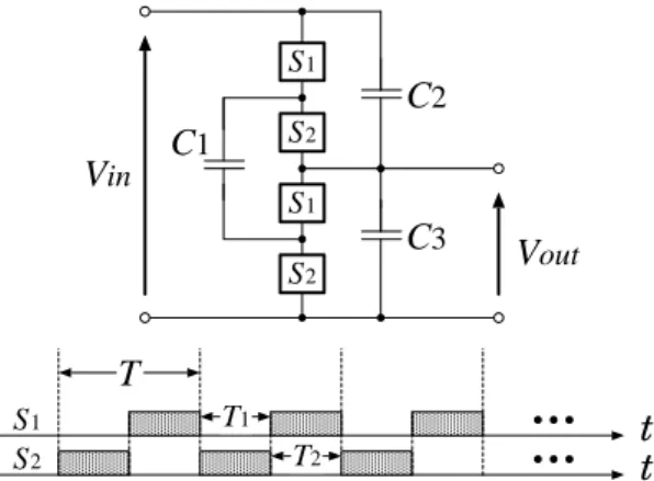
Figure 1 shows the conventional SC AC-AC converter proposed by Andersen et al (2013). The converter topology of Figure 1 is based on the SC DC-DC converter proposed by Hara et al (1997). The conventional AC-AC converter consists of four bidirectional switches and three capacitors, where bidirectional switches S1 and S2
are driven by non-overlapped two phase clock pulses. In Figure 1, the input AC voltage is divided by the capacitor C2 and C3. By changing the connection of the flying capacitor C1, the voltages of C2 and C3 are
averaged. Therefore, the conventional converter offers the following output:
in out v
v 2 1
= . (1)
Of course, as reported in (Lazzarin et al. 2012, 2013, Andersen et al. 2013, You et al. 2014), the conventional converter can achieve step-up conversion by swapping the input and output terminals. However, there is still room for improvement in the converter topology. Due to the flying capacitor, the conventional converter of Figure 1 is difficult to achieve high power efficiency and high input power factor.
Proposed Parallel-Connected AC-AC Converter:
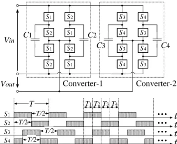
Figure 2 shows the proposed parallel-connected SC AC-AC converter. The proposed AC-AC converter consists of two converter blocks: converter-1 and converter-2. In the proposed AC-AC converter, the bidirectional switches are controlled by two phase clock pulses as shown in Figure 2. By shifting the phase of clock pulses in the converter blocks, the proposed AC-AC converter achieves small ripple noise.
In the converter block, the input AC voltage is divided by the capacitor C1 (or C3) and C2 (or C4). By
swapping the connection of C1 (or C3) and C2 (or C4), the voltages of C1 (or C3) and C2 (or C4) are averaged.
Therefore, the proposed converter offers the following conversion ratios:
in out v
v 2 1
Unlike the conventional converter of Figure 1, the proposed converter has no flying capacitors. Furthermore, as you can see from Figure 2, the proposed converter has a symmetrical topology.
Therefore, the proposed AC-AC converter can achieve not only fewer capacitors but also smaller SC resistance than the conventional AC-AC converter. Of course, by increasing the number of stages, the proposed AC-AC converter can enhance flexible conversion ratios.
C
1C
2V
inV
outT
T/2 S1S2
t
t
S1
S2
S2 S1
S1 S1 S2
S2
C
3C
4S4
S3
S3 S4
S4 S4 S3
S3
S3
t
S4
t
Converter-1
Converter-2
T1
T/2
T/2 T/2
T2T3T4
Fig. 2: Proposed SC AC-AC converter.
1 : m1
R
LV
outV
inI
inI
outR
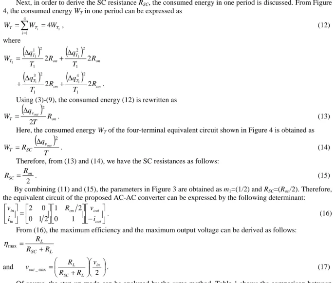
SCFig. 3: Four-terminal equivalent model.
Theoretical Model:
As an example, the characteristics of the proposed AC-AC converter are analyzed in a conversion ratio of 1/2 theoretically. In the theoretical analysis, the AC input is assumed as a staircase AC waveform in order to estimate the maximum power efficiency and the maximum output voltage. For the staircase AC waveform, the proposed AC-AC converter behaves like a DC-DC converter. Therefore, we can analyze the proposed AC-AC converter by using a four-terminal equivalent model shown in Figure 3, because it is known that an SC DC-DC converter can be expressed by a K-matrix (Eguchi et al. 2009). In Figure 3, Rsc is called the SC resistance and
m1 denotes the conversion ratio of an ideal transformer. In the theoretical analysis, these parameters are derived
by using instantaneous equivalent circuits.
Figure 4 shows the instantaneous equivalent circuits of Figure 2 in the conversion ratio of 1/2. In Figure 4,
Ron denotes the on-resistance of switches. In the steady state, the differential value of electric charges in Ck (k=1,
2, …, 4) satisfies the following equation:
0 4
1 = ∆
∑
=
i k Ti
q , (3)
where ΔqTik ((i=1, 2, …, 4) and (k=1, 2, …, 4)) denotes the electric charge of the k-th capacitor in State-Ti.
The interval of State-Ti satisfies the following conditions:
∑
= = 4 1
i i
T
T and
4
4 1
T T
T =L= = , (4)
where T is a period of the clock pulse and Ti (i=1, 2, …, 4) is the interval of State-Ti.
In State-T1, the differential values of electric charges in the input and output terminals, ΔqT1,vin and ΔqT1,vout,
are obtained as
State-T1 :
4 1 , 1 1
1v T T
T q q
q
in =∆ +∆
and , 1 2 3 4 1 1 1 1
1v T T T T
T q q q q
q
out =−∆ +∆ +∆ −∆
∆ , (5)
where 1 4
1
1 T
T q
q =∆
∆ and 2 3
1
1 T
T q
q =∆
∆ .
On the other hand, in State-T2, T3, and T4, the differential values of electric charges in the input and output
terminals are obtained as
State-T2 :
3 1 , 2 2
2v T T
T q q
q
in =∆ +∆
∆
and ∆qT2,vout =−∆qT12+∆qT22 −∆qT32+∆qT42, (6)
where 1 3
2
2 T
T q
q =∆
∆ and 2 4
2
2 T
T q
q =∆
∆ .
State-T3 :
3 2 , 3 3
3v T T
T q q
q
in =∆ +∆
∆
and ∆qT3,vout =∆qT13−∆qT23−∆qT33+∆qT43, (7)
where 1 4
3
3 T
T q
q =∆
∆ and 2 3
3
3 T
T q
q =∆
∆ .
State-T4 : ∆qT4,vin =∆qT24 +∆qT44
and , 1 2 3 4
4 4 4 4
4v T T T T
T q q q q
q
out =∆ −∆ +∆ −∆
∆ , (8)
where 1 3
4
4 T
T q
q =∆
∆ and 2 4
4
4 T
T q
q =∆
∆ .
Furthermore, the instantaneous equivalent circuit satisfies the following conditions:
4 3
2
1 T
T q
q =∆
∆ , 4 3
2
1 T
T q
q =∆
∆ , (9)
2 1
3
2 T
T q
q =∆
∆ , 2 1
3
2 T
T q
q =∆
∆ , 4 3 4 3 T T q
q =∆
∆ , 4 3
4
3 T
T q
q =∆
∆ , 2 1 4 1 T T q
q =∆
∆ and 2 1
4
1 T
T q
q =∆
∆ ,
because the proposed AC-AC converter has a symmetrical structure.
Fig. 4: Instantaneous equivalent circuits: (a) State-T1, (b) State-T2, (c) State-T3 and (d) State-T4.
Using (5) and (8), the average input current and the average output current can be expressed as
∑
= ∆ = ∆ = 4 1 , 1 i v T vin i in
in q
T T q i
and
∑
= ∆ = ∆ = 4 1 , 1 i v T v
out i out
out q
T T q
i . (10)
In (10), Δqvin and Δqvout are electric charges in vin and vout, respectively. Substituting (3)-(9) into (8), we
have the relation between the input current and the output current as follows:
out in i i 2 1 −
= . (11)
Next, in order to derive the SC resistance RSC, the consumed energy in one period is discussed. From Figure
4, the consumed energy WT in one period can be expressed as
1 4 4 1 T i T
T W W
W =
∑
i = =, (12)
where
( )
( )
on T on T T R T q R T qW 2 2
1 2 2 1 2 1 1 1 1 ∆ + ∆ =
( )
( )
onT on T R T q R T q 2 2 1 2 4 1 2 3 1
1 + ∆
∆
+ .
Using (3)-(9), the consumed energy (12) is rewritten as
(
)
on v T R T q W out 2 2 ∆= . (13)
Here, the consumed energy WT of the four-terminal equivalent circuit shown in Figure 4 is obtained as
( )
T q RW vout
SC T
2 ∆
= . (14)
Therefore, from (13) and (14), we have the SC resistances as follows:
2
on SC
R
R = . (15)
By combining (11) and (15), the parameters in Figure 3 are obtained as m1=(1/2) and RSC=(Ron/2). Therefore,
the equivalent circuit of the proposed AC-AC converter can be expressed by the following determinant:
− = out out on in in i v R i v 1 0 2 1 2 1 0 0 2
. (16)
From (16), the maximum efficiency and the maximum output voltage can be derived as follows:
L SC L R R R + = max η
and
+ = 2 max _ in L SC L out v R R R
v . (17)
Of course, the step-up mode can be analyzed by the same method. Table 1 shows the comparison between the proposed AC-AC converter and the conventional AC-AC converter. As Table 1 shows, the on-resistance of the proposed AC-AC converter is smaller than that of the conventional AC-AC converter. In other words, the proposed AC-AC converter can achieve higher power efficiency than the conventional AC-AC converter.
Table 1: Comparison of the SC resistances.
Conversion ratio 2 x 1/2 x
Proposed converter 2Ron
2
on R
Conventional converter 8Ron 2Ron
Parallel-connected conventional converter 4Ron Ron
Simulation:
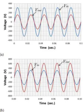
To investigate the characteristics of the proposed AC-AC converter, SPICE simulations are performed concerning the proposed AC-AC converter of Figure 2 and the conventional AC-AC converter of Figure 1. The SPICE simulations are performed under conditions that vin = 220V@50Hz, C1 = … = C4 = 33μF, Ron = 0.83Ω, T
= 10μs, and T1 = … = T4 = 5μs.
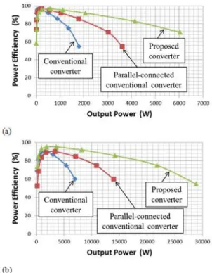
proposed AC-AC converter can achieve more than 80% efficiency. Of course, the power efficiency of the proposed AC-AC converter depends on the on-resistance of bidirectional switches, clock frequency, capacity values, and so on.
Figure 7 demonstrates the input power factor as a function of the output power. As Figure 7 shows, the input power factor of the proposed AC-AC converter is higher than that of the conventional AC-AC converter. Concretely, in the case of the 1/2x step-down conversion, the proposed AC-AC converter can improve power factor about 0.28 from the parallel-connected conventional converter when the output power is 3kW. The input power factor of the proposed AC-AC converter is more than 0.8 when the output power is higher than 0.65kW. On the other hand, in the case of the 2x step-down conversion, the proposed AC-AC converter can improve power factor about 0.08 when the output power is 10kW. The input power factor of the proposed AC-AC converter is more than 0.8 when the output power is higher than 2.5kW.
Fig. 6: Simulated power efficiency as a function of output power: (a) 1/2x step-down and (b) 2x step-up.
Fig. 7: Simulated input power factor as a function of output power: (a) 1/2x step-down and (b) 2x step-up.
Conclusion:
For electric power applications, a parallel-connected SC AC-AC converter has been proposed in this paper. The feasibility and effectiveness of the proposed AC-AC converter were confirmed by SPICE simulations and theoretical analysis. The results of this study are as follows:
2. In the case of the 1/2x step-down conversion, the proposed AC-AC converter can improve power factor about 0.28 when the output power is 3kW. On the other hand, in the case of the 2x step-down conversion, the proposed AC-AC converter can improve power factor about 0.08 when the output power is 10kW. As these results show, the proposed AC-AC converter can achieve higher power factor than the conventional AC-AC converter.
The experiment concerning the proposed AC-AC converter is left to a future study.
REFERENCES
Andersen, R.L., T.B. Lazzarin and I, Barbi, 2013. A 1-kW step-up/step-down switched-capacitor AC-AC converter. IEEE Trans. on Power Electronics, 28(7): 3329-3340.
Eguchi, K., I. Oota, S. Terada and T. Inoue2009. A design method of switched-capacitor power converters by employing a ring-type power converter. International Journal of Innovative Computing, Information and Control, 5(10 (A)): 2927-2938.
Eguchi, K., S. Pongswatd, K. Tirasesth, H. Sasaki and T. Inoue, 2010. Optimal design of a single-input parallel DC-DC converter designed by switched capacitor techniques. International Journal of Innovative Computing, Information and Control, 6 (1 (A)): 215-227.
Hara, N., I. Oota and F. Ueno, 1997. A continuous current switched-capacitor DC-DC converter with fixed-capacitors and a voltage averaging capacitor. Proc. of the 1997 International Symposium on Nonlinear Theory and its Applications, 1209-1212.
Lazzarin, T.B., R.L. Andersen, G.B. Martins and I. Barbi, 2012. A 600 W switched-capacitor AC-AC converter for 220 V/110 V and 110 V/220 V applications. IEEE Trans. on Power Electronics, 27(12): 4821-4826.
Lazzarin, T.B., M.P. Moccelini and I. Barbi, 2013. Direct buck-type AC-AC converter based on switched-capacitor. Proc of the 2013 Brazilian Power Electronics Conference, 27-31.
Terada, S., I. Oota, K. Eguchi and F. Ueno, 2004. A ring type switched-capacitor (SC) programmable converter with DC or AC input/ DC or AC output. Proc. of the 2004 IEEE Int. Midwest Symposium on Circuits and Systems, (1): pp. I-29-32.
Ueno, F., T. Inoue, I. Oota and I. Harada, 1993. Realization of a switched-capacitor AC-AC converter. Proc. of the 11-th European Conf. on Circuit Theory and Design, 1177-1180.