Easily installed automatic
extinguishing system
June 2007
Rambergveien 9Postboks 2014 3103 Tønsberg
Easily installed automatic
extinguishing system
Contents
Introduction . . . 5
Goals and principal function . . . 7
System configuration . . . 9
Activate alarm and extinguishing media . . . 9
Alarm to response personnel . . . 9
Manual activation/deactivation . . . 10
Prevention of unintentional activation . . . 10
Electrical supply . . . 10
Extinguishing system with water . . . 10
Extinguishing system with other extinguishing media . . . 10
Installation in the premises . . . 11
Important aspects . . . 11
Competence . . . 11
The “easy” installation of the system . . . 11
Reliance on the effect of the system . . . 11
Conditions for each installation . . . 13
Operating instructions . . . 13
Inspection, routine checks and maintenance . . . 13
Manufacturer’s documentation . . . 15
Test procedure . . . 17
Preface . . . 17
Test result acceptance requirements . . . 17
General requirements . . . 17
Test program . . . 19
Documentation and report . . . 20
Introduction
Healthcare policy in Scandinavia over the past 10 – 15 years has oriented towards improving conditions for people in need of care to be able to live in their own homes or adapted accommodation for as long as possible.
Recent statistics show a clear tendency towards an increase in the death rate of older people due to fire; almost 50% of people who die in fires are over the age of 60. The causes of death are asphyxiation, often caused by the extremely poisonous gas CO (carbon monoxide) which is generated by most fires, as well as the effects of heat from the fire. Life threatening conditions can arise after two to five minutes for people who cannot evacuate without assistance.
A new type of life saving extinguishing system has now been developed which can be installed in existing buildings (fire compartments) from which the occupants cannot evacuate without assistance and for which, for practical or financial reasons, safety measures involve the whole building. Tests conducted by SINTEF NBL a/s have shown that a correctly dimensioned water mist extinguishing system can safeguard life in a smaller fire compartment at least as well as a conventional residential sprinkler system, and in maintain control over the fire until personal trained in rescue and fire extinguishing can take measures.
This guide for the ”easily installed automatic extinguishing system” has been developed by the SRSA and the DSB and is based on, among other things, the tests carried out at SINTEF NBL a/s.
The guide has primarily been compiled so as to give manufacturers a common starting point from which to construct, test, install and further develop complete systems. Potential customers can also benefit from knowledge of the system requirements before deciding upon which system to buy, which in each individual case should be the one best suited to the particular circumstances. It can also provide information about systems using extinguishing media other than water.
It is at present not possible to produce standards for these systems, but some of the information has been taken from CEN/TS 14972:2006 ”Fixed firefighting systems – Watermist systems – design and installa-tion”, and for fire tests from Annex B ”Guidelines for developing representative fire test procedures for water mist systems”. It is possible, however, that parts of the guidance for ”Easily installed automatic extin-guishing system” will provide the starting point for the development of national standards.
The extinguishing system cannot be used as a measure to compensate for poor structural fire prevention. Neither can it substitute sprinkler systems (domestic sprinkler) in buildings requiring comprehensive, automatic extinguishing systems.
Goals and principal function
The “Easily installed automatic extinguishing system” is designed to gain control of the progress of the fire and thereby save the lives of people who are unable to evacuate their homes without assistance.
The extinguishing system should, in addition to giving a clear external alarm signal, be capable of maintai-ning the temperature and smoke poison below life threatemaintai-ning levels until trained personnel can reach the affected area and execute rescue and manual fire fighting.
The time required for response measures to take effect is different in each case and dependent upon the response time. Here response time implies the time between the alarm being given and response personnel becoming operational at the incident site.
The systems will perhaps not prevent injury or loss of life in all cases because of variations such as a person’s close vicinity to the outbreak of fire, e.g. fire in flammable clothing, fire source and material close to a person, a person’s disability etc. Preventive measures adapted to decrease prevalent fire risks should therefore always be assessed.
The principle functions of the extinguishing system should be tested according to the methods laid down in ”Test procedure”. Documentation on approved tests should be compiled and issued by a recognised/ accredited third party laboratory.
If minor deviations in an extinguishing system arise during a test or if major system components are changed during the process (improved/developed), the manufacturer can choose to repeat the test or in some way document that the extinguishing system will minimally be capable of extinguishing the described test fires. Such documentation should be submitted to a recognised/accredited third party laboratory for evaluation and a subsequent written report.
Extinguishing systems constructed on the basis of this guide are not approved by the authorities. It is the manufacturer which, through its documentation, shall guarantee functionality.
Products that are used for detection, alarm, firefighting, explosion or other circumstances shall be made for the purpose in a satisfactory manner and be continually maintained so as to function as expected. A docu-mented risk analysis shall be provided by the manufacturer before sale takes place. This shall include an overview of the dangers and problems that could cause undesirable incidents. Furthermore, information shall be included on the measures that have been assessed and applied in order to make the product suffi-ciently reliable and safe to use. Use and maintenance instructions shall be available in an understandable language.
Potential customers should nevertheless judge for themselves with respect to choice of manufacturer or solution on the basis of the need to:
• control the fire growth for a longer period (e.g. if the response time is uncertain) • extinguish or confine
• activate the extinguishing system quickly enough to control the fire in the immediate vicinity of an affected person
System configuration
The extinguishing system shall be configured, installed and inspected by the company which shall document that all the specified requirements are met.
The extinguishing system components, see ”Warning and alarm”, should be tested in accordance with accepted methods and their properties documented. If standard or accepted test methods are not available for specific components, the manufacturer should, through documentation, show that the component requi-rements are fulfilled.
National regulations may complement the installations.
All dimensioned parameters and other components required for the function of the system should be specified in the manufacturer’s drawings and system and installation instructions.
Activate alarm and extinguishing media
The start of a fire or of smoke (smoldering) should be detected by smoke detectors that meet the require-ments of EN 54 – 7 Smoke detectors - Point detectors using scattered light, transmitted light or ionization. This requires that a detected fire immediately alerts:
• the occupants
• people close by who can assist
• a 24-hour call centre that can alert emergency response personnel. Alarm transfer should be via a recog-nised, reliable method, possibly fulfilling national regulations.
The application of extinguishing media should then occur quickly and reliably. To prevent unwanted appli-cation, a slight delay time can be programmed in, but activation of extinguishing media should nevertheless occur while flames are at a minimal height. An extinguishing media that is activated by detectors should be part of the system that is described under ”Test procedure” in the fire tests.
Local conditions can determine how the extinguishing system is installed. See ”Residential installation” Crucial faults in the installation that could prevent function in case of fire shall:
• be clearly indicated in the system
• immediately and automatically alarm personnel in accordance with local procedures.
Alarm to response personnel
An activated detector should, in addition to giving a suitable alarm in the building, give an external alarm which is received by response personnel who can rapidly provide assistance.
• Here response personnel refers to personnel with sufficient training in the extinguishing system, rescue and fire fighting. This is organised locally.
10
Manual activation/deactivation
It should be possible to activate an extinguishing system that is activated by detectors manually also. If the system is sectioned it should be possible to activate these separately. The activation method should be clearly indicated.
It should be possible to deactivate the system manually (stop button).
Prevention of unintentional activation
There should be a system to prevent activation if a fault in the alarm unit should occur.
Deactivation of the system following unintentional activation should only be done in accordance with set procedures.
Electrical supply
An extinguishing system that is dependent upon an external electrical power supply should be connected to a circuit that does not supply rooms other than that which the system shall protect. The fuse should be marked “do not disconnect, automatic extinguishing system”. Other connections can be accepted on the grounds of a local risk assessment.
The system should not be connected via earth fault breakers/fault current relays.
Extinguishing systems that use batteries for important functions should have battery status indicators, or batteries should be replaced during checks, systematic or otherwise, and maintenance routines.
Extinguishing system with water
Any water quality requirements shall be stipulated by the manufacturer.
It should be easy to check that there is sufficient water in the system and that the water supply is under pressure.
It must not be possible to unintentionally close valves in the service piping system.
In a case of intentional closing of supply, notification of this should be routine and apply when the system is in operation and should be adapted to national or local directions. Documentation of the water supply capacity should be established through tests before the system is implemented (function test) or through tests at a recognised/accredited third party laboratory (system with tanks).
Extinguishing system with other extinguishing media
It should also be possible to apply functions and test procedures that are described in this guidance document to extinguishing systems that use extinguishing media other than water.
Installation in the premises
Important aspects
The system shall be installed in accordance with the manufacturer’s instructions.
The safe installation and use of the extinguishing system is limited to the conditions it is tested for. See section ”Test procedure”.
Expansion (extrapolation) to volumes greater than those described under “Evaluation of test results” should only occur on the basis of accepted calculation methods, be founded through tests and documented. Such documentation should be submitted to a recognised/accredited third party laboratory for evaluation presented in writing.
Before an extinguishing system is installed in a residence, a holistic evaluation (risk and vulnerability analysis) should be carried out. The following criteria should be taken into account in the evaluation and be clearly documented for each separate installation:
• number of rooms, fire-load density (flammability of furnishings)
• geometry of the room, ceiling height, volume, floor area, documented fire compartment layout • openings, ventilation conditions, air flows
• system operational time, response time for response personnel, accessibility, fire-fighting equipment • other circumstances in the room, occupants and surroundings that could result in unnecessary activation
of the system or cause it not to function as intended (e.g. smoking, abnormal fire load, function distur-bances).
Extinguishing nozzles shall be placed in accordance with the manufacturer’s instructions on the basis of the test results.
Competence
The personnel carrying out the holistic evaluation, installation and inspection should have the relevant competence as well as knowledge of the configuration of the extinguishing system, its limitations and possibilities.
The “easy” installation of the system
The installation and possible transfer of an extinguishing system should be planned to cause minimal distur-bance for occupants and should not involve time consuming activities in the accommodation or building.
Reliance on the effect of the system
impu-Conditions for each installation
Operating instructions
Easily understandable operating instructions explaining how the system works and how to use it shall be included for use by:
• Residents • Relatives
• Home-help personnel
• Maintenance personnel (caretaker) • Response personnel.
Inspection, routine checks and maintenance
Inspection
During its operational life the extinguishing system should be regularly checked in accordance with the manufacturer’s instructions or by personnel approved by the manufacturer.
The manufacturer’s final inspection instructions should ensure that the installation fulfils all the conditions, through the inspector verifying that:
• the installation performs the functions of the system as prescribed in this guide • the installation functions as projected, tested and described
• coverage and capacity are satisfactory, also with respect to possible changes to the accommodation • combining components function as they should (e.g. fire detector with external alarm is activated by the
extinguishing system)
• organizational procedures coordinate with the conditions for use (e.g. training, emergency response) Inspection personnel should have adequate knowledge of the system, products, fire science technological conditions etc.
A completed inspection should contain a report of what has been inspected, the inspection method and the results with notes on discrepancies that should be remedied immediately and those which are less urgent. A procedure for investigation into incidents shall be compiled; see the section on maintenance.
Routine checks
Routine checking entails simple daily, weekly or monthly checks of an installation following instructions given by the manufacturer. This can be carried out by home-help personnel, relatives, caretakers etc. who have sufficient knowledge to see that the system is working as laid down in the operation instructions. Example of what a routine check covers are ensuring that the installation is switched on, operative, that
14
Maintenance
Maintenance entails repair, replacement of parts, rectifying faults and service of the extinguishing system to ensure that it operates as prescribed. This is carried out as required on the basis of faults detected during routine checks following the manufacturer’s instructions.
Maintenance should be carried out by personnel with sufficient special knowledge or authorisation that is approved by the manufacturer.
Manufacturer’s documentation
Contents:
• Description of the system • Installation instructions • Summary of test results
• Directions for the individual installation including risk and vulnerability analysis
• Conditions covered by other requirements or standards (e.g. pressure vessels, extinguishing media toxi-city)
• Inspection, checks and maintenance procedures. • Competence requirements
Test procedure
The principal functions of the extinguishing system are based on the fact that the documentation for the conducted tests described in this section are compiled by a recognised/accredited third party laboratory.
Preface
The test procedure describes a method for the practical testing and verification of easily installed automatic extinguishing systems that can improve protection against fire for individuals that are unable to evacuate their homes without assistance. The test procedure describes various fire situations as well as demands for documentation that are considered necessary for the verification of the relevant type of extinguishing system. The test procedure is based on tests carried out by SINTEF-NBL during the autumn of 2005, existing test methods (IMO, UL, FM and CEN), and experience of similar extinguishing tests plus evaluations of the problem in question.
Test result acceptance requirements
The system shall minimally meet the following requirements as results of the fire tests using this method: • The average temperature for the two thermo-element trees in the room, over a period of one minute, at
a time five minutes after the first activation of the extinguishing system, must not exceed 100°C. • The CO dosage measured in the tests must not exceed 15,000 ppm/minute over a period of 20 minutes
following the first activation of the extinguishing system.
• The oxygen concentration in the room must not be less than 15% for longer than five minutes following the first activation of the extinguishing system.
These requirements are based on an evaluation of normal threshold values for that particular category of occupant with regard to the possibility of survival in a room exposed to an equivalent fire. These criteria do not apply to people that are directly affected by the actual fire in the immediate vicinity of the starting point of the fire.
General requirements
The system shall be installed in the test room according to the installation instructions from a knowledge-able company with a description of the positioning of the nozzles in relation to the geometry of the room. Written installation instructions shall be available prior to the test.
The system is tested with the given fires in the size of room (floor area, ceiling height) that it will be docu-mented for. The positioning of the nozzles shall relate to ceiling height and in relation to obstructions that may influence the distribution characteristics of the extinguishing media.
18
The results achieved by the particular system, in principle, only apply for the room size and ceiling height used in the tests. There is, however, the possibility to scale up conditions and results applying the method described in greater detail in ”Evaluation of test results”.
All the tests shall be compared for a room with quadratic floor area and a given ceiling height. The dimensions of the test room, including ceiling height, are stipulated by the supplier, and are governed by the size of room for which approval is being sought. One of three types of fire packet is placed in the test room; each of these represents a realistic fire situation which the particular type of extinguishing system is expected to cope with.
The fire packets consists of an open, accessible rapidly developing fire (sofa), a partially shielded fire with rapid development (simulated furniture), and a slow developing shielded fire (cooker fire).
The sofa fire packet is primarily based on specifications given in IMO Res.A800 (19), but with some practical simplifications and adaptations. The same applies for the furniture fire packet, which is essentially based on UL 1626, “Residential Sprinkler”. The kitchen fire packet has been developed during tests carried out by SINTEF-NBL during the autumn of 2005.
Test equipment is placed so that the test results cannot be affected by conditions such as wind, draught etc. The ambient temperature shall be in the range 20±5 °C.
Flammable material used in the tests shall be dry.
Instrumentation and registration
The test room and equipment shall have instrumentation with measurement points to measure temperature, as well as oxygen (O2) and carbon monoxide (CO) contents.
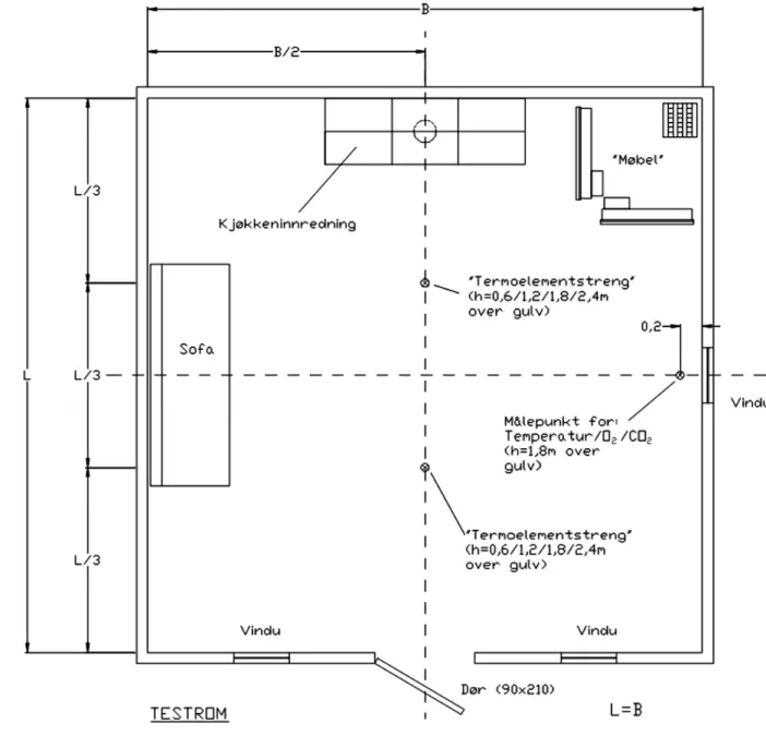
Sketches with dimensions and a more detailed description of measurement point positions are shown in figure 1.
All readings shall be taken at an interval of maximum two seconds, and all tests shall be filmed. To obtain the best possible documentation, it is suggested that IR filming be used as a complement to normal filming.
Temperature measurement
Temperature measurement is done using two thermo-element trees placed on poles straight in front of the door so that they divide the room into three, as seen from the door (see figure 1). Each thermo-element tree has four elements attached 0.6, 1.2, 1.8 and 2.4 metres above the floor. There are additional thermo-elements that measure the temperature 0.5 metres directly above each fire as well as in the actual fire source, plus a thermo-element at the measurement point for gas concentrations.
For each test the temperature outside the test room shall also be recorded in the fire test protocol. This measurement point shall be two metres directly in front of the door opening and 1.2 metres above the floor.
Gas concentrations
The measurement of O2 and CO contents is taken at a measurement point 200 mm in to the room, in the middle of the right wall as seen from the door, 1.8 metres above the floor.
For documentation of test conditions for each test, oxygen content shall be measured at a measurement point 2 metres straight outside the door and 1.2 metres above floor level.
Supply pressure of extinguishing media
The supply pressure of extinguishing media is measured at the main connection to the system after any equipment for pressure increase (pumps, pressure tanks etc.) and at the nozzle furthest from the main connection.
When pressure variations can arise at different points in the system, this shall be measured and documented via extra pressure measurement points for covering the areas concerned.
Extinguishing media flow rate
The flow rate of the extinguishing media is best measured using a flow meter placed at a specially provided point in the system. Alternatively the flow rate can be determined applying the measured k-factor and the measured supply pressure in the extinguishing system. In this case the k-factor shall be measured for the components that are included in the tests.
Test program
A test program has been compiled to include a total of six tests. Each test uses one of the fire packets described under ”Test equipment”.
Tests
The following tests shall be carried out using the system:
Test procedure
The pre-test temperature in the test room shall be 20±5 °C at all the measurement points.
Each test lasts 20 minutes from the first time the extinguishing system is activated irrespective of whether the fire is extinguished or not. Any fire or smoldering existing after this period is extinguished manually. In the case of closed door tests, the door must be closed within five seconds of the ignition of the last fire source. The furniture fire tests are started by lighting the heptane receptacle first, directly followed by the cotton wicks. The sofa fire tests are started by lighting the fire source in the sofa and the kitchen fire tests by connecting the hotplate.
Evaluation of test results
The system shall, as a starting point, minimally meet the requirements described under ”Test results” in this method.
The system is initially only certified for the room volume, ceiling height and configuration it is tested in. Test no. Fire object Door
1 Furniture Open 2 Furniture Closed
3 Sofa Open
4 Sofa Closed
5 Kitchen Open 6 Kitchen Closed
20
– Floor length changed ±20 %
– Distance from extinguishing nozzles to possible fire source changed ±20 %
Total room volume can be varied by ±50 %, providing that the supply of extinguishing media per m3 room
volume is scaled up or down proportionately. A prerequisite for evaluation of a given installation is that the distribution of extinguishing media equates to that in the test.
Documentation and report
The test results shall be documented in a report which shall meet the following minimum requirements: • Title
• Name and address of the test laboratory, including a description of the test procedure
• Unique identification of the report (e.g. serial number or similar), with the same identification on each page, the total number of pages and identification of the final page.
• Name and address of owner.
• Description of the tested system, including clear, unambiguous identification of its component parts. • Date for reception of equipment and components, as well as the dates and times of the various tests. • Description of test hall and test conditions as well as a description of the test equipment.
• Description of key data for identification of equipment and measurement instruments used in the tests, including important dimensions and descriptions of material consumed.
• Test results presented as ratios for important values in text or table format, as well as in the form of time against measured value graphs for all the readings taken.
• The following measured values and observations shall as a minimum be included: – Test start time.
– Time to ignition and time to system activation taken from the test start time. – Time(s) for possible activation of the system in intervals.
– Completion of test.
– Images of damage caused by the test.
– Temperature readings and values for O2 and CO in graph form. – Extinguishing system pressure and flow rates in graph form. – Number of nozzles/units triggered.
• Conclusions, including description of possible deviations from the test method. • Names and roles of test personnel.
• Name, role and signature of the person(s) responsible for the contents of the report.
Test equipment – sketches, dimensions, requirements and
key data
Test room
The test room is built with quadratic floor area, where length, width and ceiling height are dictated by the size of room for which approval is being sought. The room is built as a framework construction, with internal walls and ceiling of 13mm plaster board. The floor must be of non-flammable material. The room shall have a 900 x 2100 mm door at floor level centrally placed in one of the walls. It must be possible to
close the door. The room and door must be sealed to a degree that would meet normal residential standards. The test room shall have three 500 x 500mm windows for observation and filming, one each side of the door and one on the right side wall as seen from the door. The principal dimensions and schematic arran-gement of the room are shown in figure 1.
Prior to each test and the fitting of wall panels, the walls ceiling and floor must be free of water.
Figure 1: Principal dimensions and test arrangement in the test room.
Fire packet - Sofa
22
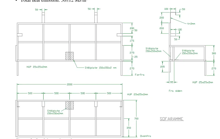
Steel frame
The sofa is built as a welded steel frame from 25 x 25 x 2 mm wall thickness square tube as shown in figure 2. The frame consists of a 700 x 2000 mm seat section and a 725 x 2000 mm backrest section. The seat and backrest both have three cross struts and one lengthways strut made of the same square tubing. The backrest and seat section are joined at a right angle and have a rectangular arm rest at each end. Both the seat and backrest have a 150 x 150 x 2 mm thick steel plate, directly under the ignition source to prevent this from burning through the mattress and falling onto the floor during a test. The seat and backrest assembly has two front legs, 270 mm long and two back legs 205 mm long. The backrest has four 50 mm wide hooks, as shown in figure 2, to prevent the cushion from falling forward during a test.
Mattresses
Plastic foam mattresses (PUR) with loose cotton covers shall be used. The density of the foam in the mattresses shall be approximately 33 kg/m3 and the cotton covers have a basis weight of 140 – 180 g/m2.
The mattresses and the covers shall not be flame proofed.
The plastic foam shall be tested in comparison to ISO 5660, ”Cone Calorimeter Test” applying the following test conditions:
• Heat radiation level: 35 kW/m2
• Horizontal placement of the test material • Protection of test object: 50 mm
• No test frame (retainer frame) • Criteria for test results:
• Time until ignition: 2-6 seconds
• Average heat emission 180 seconds after ignition, HRR, q180: 270±50 kW/m2
• Minimum effective combustion heat: 25 MJ/kg • Total heat emission: 50±12 MJ/m2
Ignition source
The fire is started using 10 mm thick asphalt impregnated, wind-resistant fibreboard. This is cut into 60 x 60 mm pieces which are assemble to form a 60 x 60 x 75 mm block (the final piece is split to give a thickness of 0.5 mm). Prior to the test the block is soaked with 120 ml of heptane and placed in a small plastic bag.
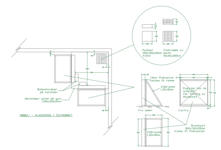
Fire packet – simulated furniture
The test arrangement consists of two plastic foam cushions and a stack of wood placed above a receptacle holding heptane and positioned in the back, right corner of the test room as seen from the door.
The cushions shall consist of two 100 mm thick pieces of plastic foam, unupholstered and of the type specified for the sofa fire packet. The cushions shall be 810 mm wide, 760 mm high and be glued onto a 12 mm thick board of untreated plywood using contact adhesive. The distance from the edge of the board to the plastic foam cushion is 30 mm at the bottom edge and 15 mm along the edge of each side. The sheets of plywood are 840 mm wide and 790 mm high and are securely bolted to the steel frames which hold them in an upright position. The plastic foam cushions and sheets of wood must be dry prior to the test. The cushions are placed 1000 mm out from each of the walls in corner. The two cotton wicks of approxi-mately 65 x 150 mm and dipped in heptane are placed at the position of the cushions’ closest lower corners. Each wick is placed on a brick as shown in figure 3.
The stack of wood consists of four layers, each with four 305 mm long, 40 x 40 mm pieces of spruce. The layers are position at right angles to each other, the weight of the pile is between 2.5 and 3.2 kg and the wood shall be dry prior to the test.
The receptacle for the heptane is 300 x 300 x 100 mm (l x b x h). Prior to the test this is filled with 0.25 litres of heptane on 0.5 litres of water, and the stack is placed on it. The heptane receptacle and the woodpile are placed in the corner of the room, 50 mm from each wall.
The two walls with the cushions and wood stack as well as the ceiling in the same area are clad with untre-ated, dry plywood approximately 4 mm thick. The sheets are mounted on the walls 2.4 meters out from the corner and the equivalent area of the ceiling.
24
Figure 3: Furniture simulation with heptane receptacle and wood stack.
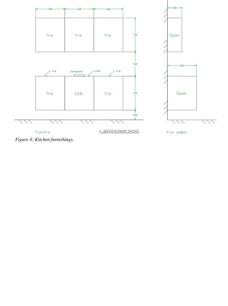
Fire packet - Kitchen
The packet represents a simple kitchen arrangement made of wood. It is 1800 mm wide and is divided into three sections of 600 mm each. The upper cupboards are 700 mm high and 300 mm deep. The lower cupboards are 700 mm high and 600 mm deep. The worktop is 900 mm above the floor. The distance between the worktop and the underside of the upper cupboards is 500 mm.
The fronts and the worktop are of solid pine made up of glued strips which are about 18 mm thick. The sides, tops and bottoms of the cupboards are of approximately 12 mm thick chipboard.
The middle section of the lower cupboard consists of a stove made of 2 mm thick sheet steel with a 2000 watt hot plate at the centre of the top panel. The overheating protection for the hot plate must be discon-nected if such is fitted.
A cast iron frying pan is placed on the hob. This is filled with 200 ml of soya oil with a self ignition tempe-rature of about 360 °C. Two pieces of wood, type “Crib 7” are placed in it. This wood is explained in: BS5852:2006; ”Methods of test for assessment of the ignitability of upholstered seating by smoldering and flaming ignition sources”.
Rambergveien 9 Postboks 2014 3103 Tønsberg
Telf.: 33 41 25 00
Faks: 33 31 06 60
[email protected] www.dsb.no
Tema
HR - ????