In-Situ
Observation of Crystal Alignment under a Magnetic
Field Using X-ray Diffraction
Takenori Kohama
1;*1, Hiroki Takeuchi
1;*1, Manabu Usui
1;*2, Jun Akiyama
1;*3,
Mun-Gyu Sung
1, Kazuhiko Iwai
1and Shigeo Asai
21Department of Materials, Physics and Energy Engineering, Nagoya University, Nagoya 464-8603, Japan 2Innovation Plaza Tokai Japan Science and Technology Agency, Nagoya 457-0063, Japan
The crystal alignment behavior of bismuth particles in the presence of an imposed static magnetic field was examinedin situby X-ray diffraction. Because the c-plane of a bismuth crystal is aligned perpendicular to the direction of a magnetic field, the temporal variation in the (110) peak intensity of bismuth was measured by X-ray diffraction to determine the crystal alignment. The alignment time decreased as the magnetic field strength increased. This tendency is similar to that calculated for the relaxation time. The difference in the magnetic susceptibility between the magnetically easy and hard axes is the driving force for the crystal alignment, and aggregation of the bismuth particles decreases this driving force. The effective difference in magnetic susceptibility for aggregated bismuth particles was estimated by measuring the alignment time of the particles under magnetic fields of various strengths. The estimated effective difference in magnetic susceptibility generally increases with a decreasing magnetic field strength. Furthermore, the interference to crystal rotation caused by the interaction between the induced current and the imposed magnetic field is negligible in this study. To decrease the strength of the magnetic field required for alignment of crystals, the number of small particles should be reduced. [doi:10.2320/matertrans.MI200719]
(Received June 12, 2007; Accepted August 24, 2007; Published October 25, 2007)
Keywords: crystal alignment, X-ray diffraction, magnetic anisotropy, in-situ observation, magnetic susceptibility
1. Introduction
A magnetic field can have useful functions, such as crystal alignment,1)levitation,2)separation,3)and flow control of an electrically conductive fluid. In particular, crystal alignment is an attractive tool for producing functional materials, because physical properties of materials, such as the electric, magnetic, thermal, and mechanical properties, can be con-trolled if these properties have an anisotropic nature. With the development of the technology of superconducting magnets, crystals of nonmagnetic, magnetically anisotropic materials such as metals,4–6)ceramics,7,8)and polymers9)can be aligned
by the imposition of a strong magnetic field. To form unidirectionally aligned crystals for a material with a magnetic anisotropy ofc< a, a combined process involv-ing the imposition of a magnetic field and the rotation of a sample has been proposed.9,10)By using this method, a bulk
form of hydroxyapatite with unidirectionally aligned crystals has been produced.11)A theoretical analysis for the optimi-zation of this process has been performed.12) Furthermore, crystal alignment of a tin–lead binary alloy primary phase in a magnetically preferred direction can be controlled by changing the duration of an imposed electric current and static magnetic field during solidification.13)For optimization
of these crystal-alignment processes, the rotation behavior of crystals suspended in a solvent in a magnetic field should be clarified.
We examined the in situ crystal-alignment behavior of bismuth particles in the presence of a static magnetic field by
in situx-ray diffraction (XRD) studies.
2. Experimental Details
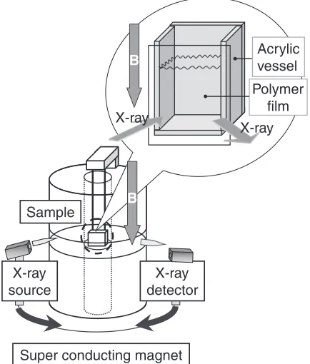
The experimental apparatus is shown in Fig. 1. Bismuth particles (2.67 g) were mixed with liquid polydimethylsilox-ane (4 mL) to form a slurry. The viscosity and density of the polydimethylsiloxane were 50 Pa.s and 1000 kg/m3, respec-tively. An acrylic vessel containing the slurry was placed in the bore of a superconducting magnet for the imposition of a vertical static magnetic field on the slurry. The size distribution of the bismuth particles used in this experiment is shown in Fig. 2. The mean diameter was 8.25mm. The
Sample
X-ray detector X-ray
source
B
Polymer film Acrylic vessel
X-ray
X-ray
B
Super conducting magnet
Fig. 1 Experimental apparatus.
*1Graduate Student, Nagoya University
*2Graduate Student, Nagoya University, Present address: IBIDEN Co.,
LTD, Ogaki 503-8604, Japan
*3Graduate Student, Nagoya University, Present address: Institute for
Molecular Science, Okazaki 444-8585, Japan
Special Issue on Structural and Functional Control of Materials through Solid-Solid Phase Transformations in High Magnetic Fields
[image:1.595.318.535.508.763.2]ratio of particles with diameters of less than 0.389mm, 1mm, and 20mmwere 1.0, 4.4, and 98 vol.%, respectively.
The crystallographic structure of bismuth can be consid-ered as a hexagonal structure, as shown in Fig. 3, and bismuth crystals show anisotropy in magnetic susceptibility. Because the magnetic susceptibility of bismuth in the direction of the a-axis is 1:77104 and that in the direction of the c-axis is1:24104, the c-axis must be parallel to the magnetic field direction. This means that the peak XRD intensity in a plane parallel to the c-axis increases on imposition of a vertical magnetic field in this experiment, because the X-ray direction is in a horizontal plane, as shown in Fig. 1.
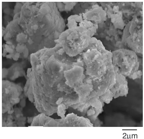
[image:2.595.304.548.70.306.2]The effective difference in magnetic susceptibility of the bismuth particles used in this experiment must be small in comparison with that of a single crystal, because the bismuth particles with nonspherical shapes aggregate, as shown in Fig. 4.
The XRD results in the presence and absence of a magnetic field are shown in Fig. 5. The (110) peak is intensified by the imposed magnetic field, whereas the (104) peak is
sup-pressed. Therefore, the (110) intensity of the bismuth crystal was chosen as an index of the crystal alignment, and its temporal variation was measured for various strengths of the magnetic field. The (110) peak angle, which was 39.6in the absence of the magnetic field, changed slightly on imposition of the field. We therefore searched for the peak angle between 39.4and 39.8in 0.01increments: this search took
about 30 s. The results measured in magnetic fields of 0, 1, and 2 T are shown in Fig. 6. The (110) peak intensity did not change with time, although it showed a small fluctuation in the absence of the magnetic field. On the other hand, the intensity of the (110) peak measured in a 1 T magnetic field increased gradually with time and it reached a plateau after a certain time. That is, the bismuth particles in the polydime-thylsiloxane rotate to the magnetically preferred direction. The alignment time in this experiment was defined as the period from the insertion of the sample into the bore of the magnet to the time at which the (110) peak intensity reached 90% of its maximum value. This time is indicated in Fig. 6 by the horizontal line showing 90% of the maximum value.
diameter/m
cumulati
v
e ratio /
-frequenc
y /
-10-7 10-6 10-5
0 0.05 0.1 0.15
0 0.5 1
10-4
Fig. 2 Size distribution of bismuth powder.
c
a
Fig. 3 Crystallographic structure of bismuth.
2
µ
m
Fig. 4 SEM picture of bismuth particles.
90 2θ /degree
Intensity , a.u.
70
30 50
(104)
(110)
(110)
(104)
Without magnetic field
With 1T magnetic field
[image:2.595.64.277.72.199.2] [image:2.595.63.275.245.491.2] [image:2.595.321.532.341.508.2]The driving force for sedimentation of the bismuth particle is the difference in density between the bismuth particles and polydimethylsiloxane, which can be expressed as follows.
Fg¼ ðBipolymerÞgVBi ð1Þ where g is the acceleration of gravity,VBiis the volume of bismuth particles,Biis the density of bismuth, andpolymeris the density of polydimethylsiloxane, respectively.
This force is calculated as2:311011N for a particle with a mean diameter of 8.25mm. Because the (110) peak intensity does not change in the absence of a magnetic field, sedimentation of the bismuth particles in this experiment can be neglected.
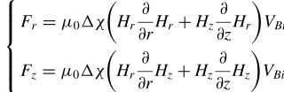
In the presence of the magnetic field, the magnetization force affects the motion of the bismuth particles. The following equations are used to evaluate the magnetization force.
Fr¼0 Hr
@
@rHrþHz
@ @zHr
VBi
Fz¼0 Hr
@
@rHzþHz
@
@zHz
VBi
8 > > > < > > > :
ð2Þ
whereris the radial direction,zis the axial direction,0 is the magnetic permeability in a vacuum, andis difference in magnetic susceptibility between bismuth and polydime-thylsiloxane, respectively.
The magnetization force is therefore proportional to the difference in magnetic susceptibility between the bismuth particles and the polydimethylsiloxane. The magnetic sus-ceptibility of the polydimethylsiloxane is neglected in the calculation, because the magnetic susceptibility of polymers is usually of the order of10614)which is small in comparison
with that of bismuth. The calculated forces for 8.24-m m-diameter bismuth particles in the radial and axial directions are Fr¼1:751013N and Fz¼9:731013N,
[image:3.595.78.264.71.328.2]respec-tively, when the strength of the magnetic field is 3 T. The magnetization forces can therefore be ignored in this experi-ment, since these forces are smaller than the force caused by the density difference.
Figure 7 shows the relation between the maximum value of the (110) peak intensity detected by XRD and the strength of the magnetic field. Because the maximum value has a positive correlation with the number of aligned particles, the number of aligned particles increases between the 0 and 1.5 T; however, the additional effect of the magnetic field on the number of aligned particles appears to be slight at magnetic fields of more than 1.5 T. Figure 8 shows a plot of the alignment time against the strength of the magnetic field. The alignment time decreases with increasing magnetic field strength. In particular, it decreases markedly between the 1 T and 2 T. The alignment time at fields of more than 2 T may be weakly dependent on the strength of the magnetic field, but this is not clear from this experiment. This tendency agrees with that for the maximum magnitude, shown in Fig. 7. Therefore, almost all the bismuth particles in the vessel rotate to the magnetically preferred direction, and the rotation time is not strongly affected by the magnetic field over a certain strength of magnetic field. The critical strength in this experiment is around 2 T.
3. Discussion
The law of conservation of angular momentum for a spherical single crystal suspended in a solvent with viscosity
can be expressed as follows:
µ
0H=0T
Intensity / cps
1T
330s
2T
70s
0
100
200
300
400
500
Time/s
100
200
300
400
100
200
300
400
100
200
300
400
0
0
0
Fig. 6 Time variation of Bi(110) intensity.
3.0
0 1.0 2.0
µ0H/T
Intensity / cps
100200 300 400
0
Fig. 7 Maximum Bi(110) intensity under different magnetic field strength.
3.0
0 1.0 2.0
0 100 200 300 400
alignment time / s
µ0H / T
[image:3.595.319.535.75.210.2] [image:3.595.321.534.253.392.2] [image:3.595.82.242.576.628.2]2 5R
5d 2
dt2 þ8R 3d
dtþ 4 15R
5 02H2
d
dt
¼2R
3
3 0H
2sin 2 ð3Þ
whereH,R,t,,,, andare the magnetic field strength, crystal radius, time, crystal density, the angle between the magnetically easy axis of the crystal and the magnetic field direction, the electric conductivity, and the difference in magnetic susceptibility between magnetically easy axis and magnetically hard axis, respectively.
The inertial term is dominant during the initial stages of crystal rotation. The effective time of the inertial term, teff, is
estimated by equating the inertial term and the viscous term.
teff ¼
R2
40 ð4Þ
The effective time is calculated to be 11010s for a spherical bismuth crystal under our experimental conditions. The inertial term can therefore be neglected.
The temporal variation of the angle is derived from eq. (3) as follows, when the inertial term is neglected.15)
tan¼tan0exp t
ð5Þ
¼30þR
2 02H2 502H2
0 ð6Þ
where 0 is the initial angle between the magnetic field direction and the magnetically easy axis and is the relaxation time for the crystal alignment, respectively.
The relaxation time is calculated by using eq. (6) and compared with the measured alignment time. The results are shown in Fig. 9. The relation between the magnetic field strength and the measured alignment time is similar to the relation between the magnetic field strength and the calculated relaxation time, although the measured alignment time is longer than the calculated relaxation time under the same strength of magnetic field. This is because the definition of the relaxation time is different from that of the measured alignment time. Actually, the thirty times increase in the value of the relaxation time agrees well with the measured alignment time, as shown in Fig. 9. The relaxation time in the case where the electric conductivity is zero was also calculated. The calculated curve is identical to the curve in which the electric conductivity is considered, so the effect of the induced electric current on the crystal alignment can be neglected in this experiment.
The average angle between the direction of the magnetic field and the c-axis, immediately after the imposition of the magnetic field is calculated to be one radian, by using equation (7).
i¼ Z =2
0
sind Z=2
0
sind
¼1 ð7Þ
The effective magnetic susceptibility difference is then estimated from eqs. (5) and (6), by assuming that the final and initial angles are 1(0.017 radians) and 57.3(1 radian),
respectively. The results are listed in Table 1. The estimated effective magnetic susceptibility difference decreases rough-ly with the increase in the magnetic field strength. This is because only particles with a large difference in magnetic susceptibility align in the magnetically preferred direction under a weak magnetic field, whereas particles with a small magnetic susceptibility difference also align in the magneti-cally preferred direction under a strong magnetic field. Actually, the effective magnetic susceptibility difference is relatively small when the (110) peak intensity, shown in Fig. 7, is relatively large, whereas the magnetic susceptibility difference is relatively large when the (110) peak intensity is relatively small.
The ratio of the magnetization energy caused by the magnetic susceptibility difference to the thermal disturbance, Xis indicated as follows:
X¼1
20H 24
3r 3
kBT ð8Þ
where kB is the Boltzmann constant and T is the absolute temperature.
This ratio was calculated for various strength of the magnetic field and various crystal sizes at a temperature of 298 K. The magnetic susceptibility differences adopted in the calculation were5:3105for a bismuth single crystal and5:3106 for the bismuth particles, because the estimated effective magnetic susceptibility difference of the bismuth particles is roughly one tenth that of single crystalline bismuth in a magnetic field strength in the range 1–3 T, as shown in Table 1. The results are shown in Fig. 10. In the case of a magnetic susceptibility difference of 5:3105 and a bismuth particle diameter of 8.25mm, the magnetization energy is much larger than the thermal disturbance. The magnetization energy is dominant even for a bismuth particle diameter of 8.25mmand a magnetic susceptibility difference of5:3106. The ratio is calculated at 268 when the particle diameter is 1mm, the magnetic field strength is 1 T, and the magnetic susceptibility difference is 5:3106. However,
100 200 300 400
alignment time / s
0 1 2 3
µ
0H/Tcal. (τ)
measured
cal.(30τ)
[image:4.595.68.273.75.184.2]Fig. 9 Comparison of alignment time between measured one and calcu-lated one.
Table 1 Estimated magnetic susceptibility difference of the bismuth particles.
0H/T ðÞ
0.5 2:05105
1 5:13106
1.5 5:57106
2 6:05106
[image:4.595.302.549.94.171.2]some particles do not align in the magnetically preferred direction under our experimental conditions, as mentioned in above. Therefore, the probability of an anglebetween the magnetic field direction and the magnetically easy axis was calculated for various crystal sizes at a magnetic suscepti-bility difference of5:3106.16)The angle scattering range
increases markedly as the particle size decreases, as shown in Fig. 11. Because the proportion of particles smaller than 0.389mmis 1% and of those smaller than 1mmis 4.4% in this experiment, some of these small particles are in a nonaligned state from the viewpoint of the (110) peak detection in the XRD. These nonaligned small particles reduce the maximum value of the (110) peak intensity. The angleconcentrates by increasing the magnetic field strength under the magnetic susceptibility difference of5:3106, as shown in Fig. 12. This is the reason why the maximum value of the (110) peak intensity and the alignment time are nearly saturated at magnetic fields of more than 2 T. These results show that the small-sized particles should be reduced to decrease the strength of the magnetic field necessary for the crystal-alignment process.
4. Conclusion
By using XRD, we examined the alignment behavior of bismuth particles crystals in order to elucidate their rotational
behavior when suspended in a solvent in a static magnetic field. The followings are the main results that we obtained.
# The effective difference in magnetic susceptibility of aggregated particles can be estimated by measuring the alignment time of the particles in a magnetic field. # The difference in magnetic susceptibility depends on
the magnetic field strength.
# The small-sized particles should be reduced to decrease the magnetic field strength necessary for the crystal-alignment process.
Acknowledgement
This research was partially supported by Iron and Steel Institute of Japan and JSPS Asian Core Program ‘‘Construc-tion of the World Center on Electromagnetic Processing of Materials’’.
REFERENCES
1) S. Li, K. Sassa, K. Iwai and S. Asai: Mater. Trans.45(2004) 3132– 3129.
2) K. Iwai and S. Asai: Modeling and Simulation in Materials Science and Engineering3(1995) 473–484.
3) Y. Tanaka, K. Sassa, K. Iwai and S. Asai: Tetsu to Hagane81(1995) 1120–1125.
4) H. Morikawa, K. Sassa and S. Asai: Mater. Trans. JIM39(1998) 814– 818.
5) M. Tahashi, M. Ishihara, K. Sassa and S. Asai: Mater. Trans.44(2003) 285–289.
6) M. Usui, K. Iwai and S. Asai: ISIJ Int.46(2006) 859–863.
7) T. Suzuki, Y. Sakka and K. Kitazawa: J. Cera. Soc. JP.109(2001) 886– 890.
8) Y. Sakka and S. Suzuki: J. Cera. Soc. JP.113(2005) 26–36. 9) T. Kimura: Polymer Journal.35(2003) 823–843.
10) J. Akiyama, M. Hashimoto, H. Takadama, F. Nagata, Y. Yokogawa, K. Sassa, K. Iwai and S. Asai: Mater. Trans.46(2005) 203–206. 11) J. Akiyama, M. Hashimoto, H. Takadama, F. Nagata, Y. Yokogawa, K.
Sassa, K. Iwai and S. Asai: Mater. Trans.46(2005) 2514–2517. 12) J. Akiyama, H. Asano, K. Iwai and S. Asai: J. Japan Inst. Metals71
(2007) 108–112.
13) M. Usui, K. Iwai and S. Asai: ISIJ Int.46(2006) 859–863. 14) M. Yamato: Kobunshi Ronbunshu61(2004) 433–441.
15) T. Sugiyama, M. Tahashi, K. Sassa and S. Asai: ISIJ Int.43(2003) 855–861.
16) K. Kitazawa:new magneto-science, (Industrial Publishing & Consult-ing, Inc., Tokyo, 2002).
0.1 1 100
102
104 106
kB
T
µ0H/T
10
6
− = 5.3×10 ∆
m 2R = 1µ
−6
= 5.3×10 ∆
m 2R = 8.25µ
5
−
= 5.3×10 ∆
m 2R = 8.25µ
(1/2)
µ0
∆χ
(4/3)
π
r
3
H
2
χ
χ
[image:5.595.64.277.76.229.2]χ
Fig. 10 Ratio of Magnetic energy difference to thermal disturbance.
2R =0.389µm 2R =1µ m
2R =8.25µm
µ
0H=1Tθ
/degree20 10
0
Probability/-0.02
0.01
0 0.015
0.005
θ
µ
0HFig. 11 Probability of angle, between magnetic field direction and magnetically easy axis under different crystal size.
θ
/degree20 10
0
2R =0.389 µm
µ
0H =3Tµ
0H =2Tµ
0H =1T0.01
0 0.015
0.005
θ
µ
0H[image:5.595.319.536.77.228.2] [image:5.595.62.277.272.427.2]