Corrosion of CrN-Coated Steels in Liquid Pb-Bi
Yuji Kurata and Masatoshi Futakawa
Japan Atomic Energy Agency, Tokai-mura, Ibraki 319-1195, Japan
Corrosion tests of CrN-coated steels were conducted in liquid lead-bismuth (Pb-Bi) at 450C and 550C for 3000 h to investigate the
applicability of CrN coating to a liquid Pb-Bi environment. CrN coatings on F82H (Fe-8Cr-2W-0.3V-0.04Ta-0.1C) and 316SS exhibited good compatibility in liquid Pb-Bi during corrosion test at 450C. The CrN coating layer suffered heavy damage such as cracking and spalling, and
showed no effectiveness as a protective layer in corrosion test at 550C. Nickel and chromium in 316SS dissolved into Pb-Bi through the
damaged coating layer at 550C. It is considered that stresses caused by the difference of thermal expansion coefficients between CrN and steels
led to cracking and spalling of the CrN coating through corrosion attack by liquid Pb-Bi at 550C. [doi:10.2320/matertrans.48.519]
(Received October 11, 2006; Accepted January 15, 2007; Published February 25, 2007)
Keywords: CrN coating, lead-bismuth, corrosion, compatibility, cracking, dissolution
1. Introduction
Liquid lead-bismuth (Pb-Bi) has been studied as a spallation target and a coolant of an accelerator driven system (ADS)1–3) for the transmutation treatment of
long-lived radioactive wastes and as a coolant of a fast critical reactor. One of difficulties to apply Pb-Bi to nuclear systems is the corrosiveness of liquid Pb-Bi to structural materials. For this reason studies on corrosion of structural steels in liquid Pb-Bi have been made.4–15) In the present design of ADS, inlet and outlet temperatures of liquid Pb-Bi coolant are 330C and 430C, respectively. Efforts have been made to reduce the temperature of fuel cladding tubes since the maximum temperature of the outer surface of fuel cladding tubes attains to about 600C.
Recently, ceramic coatings such as CrN and TiN have been developed for the purpose of their application to nuclear systems. Since CrN and TiN coatings produced by PVD ion-plating method are compact, hard and adhesive to substrate, they are expected to be used as materials for instruments which need wear and corrosion resistance.16,17)Pre-stressed
steels coated with TiN, CrN and DLC (diamond like carbon) were exposed to flowing liquid Pb-Bi at 350C.15)However,
corrosion data at higher temperatures have not been reported for these coating materials. The CrN coating has a possibility as a protective film for high temperature corrosion in liquid Pb-Bi because its heat resistance is high.16,18)Furthermore, the pin-hole density of the CrN coating is lower than that of the TiN coating16,17)and neutron irradiation data of the CrN
film have been obtained.16)
The purpose of the present paper is to investigate the applicability of the CrN coating to a liquid Pb-Bi environ-ment at 450C and 550C.
2. Experimental
Specimens used in this study were CrN-coated F82H martensitic steel and austenitic 316SS. F82H (Fe-8Cr-2W-0.3V-0.04Ta-0.1C) steel is a reduced-activation one devel-oped for nuclear fusion reactors. The size of corrosion specimens was 15mm30mm2mm, and a hole of 7.2 mm diameter for installation was made at the top of the
specimen. The CrN film was coated on F82H and 316 steels by a cathodic arc ion-plating method at Japan Coating Center Co, Ltd. This method can produce compact and uniform coatings with low pin-hole density.16,17) The substrate
temperatures were kept around 400C and the film thickness
was controlled to about 6mmby treating time.
The corrosion tests were conducted in liquid Pb-Bi using the static corrosion apparatus shown in Fig. 1. Components of the apparatus contacting liquid Pb-Bi were made of quartz. As received eutectic Pb-Bi (45Pb-55Bi) of 7 kg was used in each test. Corrosion tests were conducted at 450C and 550C for 3000 h, respectively. The Pb-Bi was melted in a pot under Ar gas environment. Ar gas of 99.9999% purity was used as a cover gas over the liquid Pb-Bi. PbO was formed on the surface of the liquid Pb-Bi and corrosion tests were made under oxygen-saturated conditions. Oxygen saturation concentration was estimated to be 3:210 4 mass% at 450C and1:210 3mass% at 550C using the
equation in the literature.4)
Test specimens were cleaned in silicone oil at about 170C
after the corrosion tests to remove Pb-Bi adhering to the surface of the specimens. However, there was adhesive Pb-Bi left on some parts of the specimen surface. Analyses were
250 φ110 90 Thermocouple Furnace Ar gas Pot (Quartz) Corrosion Specimen (15x30x2t) Unit:mm Pb-Bi
[image:1.595.316.539.578.765.2]made using an optical microscope and a scanning electron microscope (SEM) with energy dispersion X-ray (EDX) for the specimen plated with copper to protect coating and corrosion films during polishing.
CrN-coated F82H and 316SS were heated in Ar gas at 550C for 20 h to investigate whether the CrN coating splits
or not on account of only stresses caused by the difference of thermal expansion coefficients between CrN and the metal. The surface of the CrN-coated steels before and after heating was observed using a laser microscope.
3. Results and Discussion
3.1 Corrosion test at 450C
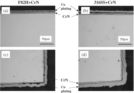
Figure 2 shows optical micrographs of cross sections of CrN-coated F82H and 316SS specimens after corrosion test in liquid Pb-Bi at 450C for 3000 h. As shown in this figure,
the CrN coating films on both steels were sound and proof against corrosion attack at 450C. Neither cracking nor
spalling in CrN coating layers was found both at the flat parts (Fig. 2(a) and (b)) and at the corner parts (Fig. 2(c) and (d)) for F82H and 316SS specimens.
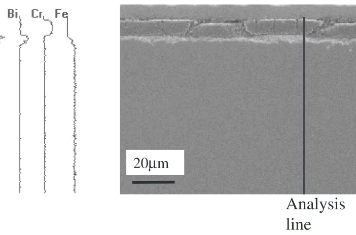
Figure 3 shows the result of line analysis by EDX for the cross section of the CrN-coated F82H after corrosion test at 450C. Peaks of Cr and N are found at the coating layer.
Dissolution of Cr and Fe into liquid Pb-Bi through the coating layer is not observed. As shown in Fig. 4, dissolution of Ni, Cr and Fe through the coating layer is also not recognized in CrN-coated 316SS after corrosion test at
450C. The CrN coating on 316SS is proof against corrosion
attack by liquid Pb-Bi at 450C.
3.2 Corrosion test at 550C
Figure 5 shows optical micrographs of cross sections of CrN-coated F82H and 316SS specimens after corrosion test in liquid Pb-Bi at 550C for 3000 h. As indicated in Fig. 5(a),
there exist large cracks going through the coating layer on F82H steel in corrosion test at 550C. Decohesion or spalling
of the CrN coating layer occurs due to formation of large cracks at the near corner parts of F82H and 316SS specimens (Fig. 5(c) and (d)). Pb and Bi penetrated through the large cracks and corrosion attack of liquid Pb-Bi to F82H steel proceeds under the coating layer. Grain boundary corrosion is recognized at the part where the CrN coating on F82H steel peeled off at 550C (Fig. 5(c)). As shown in Fig. 5(b), a
degraded layer was formed under the CrN coating even at the parts where the CrN coating remained on 316SS specimen. The degraded layer is a ferrite layer formed in austenitic 316SS. The formation of the ferrite layer was reported for 316SS specimens without coating in corrosion tests at 550C.8,9) The thickness of the ferrite layer formed in
316SS is about 115mmat the part where the coating spalled off (Fig. 5(d)) while it is about 55mmat the part where the coating remained (Fig. 5(b)).
Peaks of Cr and N are observed at the coating layer with large cracks for CrN-coated F82H specimen after corrosion test at 550C as shown in Fig. 6. Peaks of Pb and Bi, which entered through the large cracks, are also found under the
50
µ
m
50
µ
m
Cu
plating
CrN
(c)
(d)
Fig. 2 Optical micrographs of cross sections of specimens after corrosion test in liquid Pb-Bi at 450C for 3000 h. (a) and (c) CrN-coated
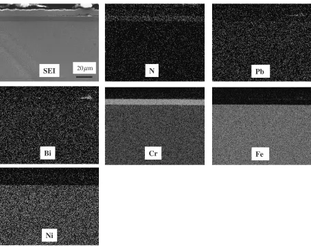
[image:2.595.70.526.74.390.2]coating layer. Figure 7 shows the result of element mapping for the cross section of CrN-coated 316SS after corrosion test at 550C. It seems that dissolution of Cr and N from the coating layer into liquid Pb-Bi does not occur since there
exist peaks of Cr and N at the coating layers of F82H and 316SS after corrosion test in liquid Pb-Bi at 550C for 3000 h. Under the coating layer, selective dissolution of Ni and Cr produce a ferrite layer where Pb and Bi penetrate.
Analysis
line
20
µ
m
Fig. 3 Line analysis of the cross section of CrN-coated F82H after corrosion test at 450C.
N
SEI
20µPb
Bi
Cr
Fe
Ni
m
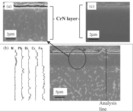
[image:3.595.105.491.70.306.2] [image:3.595.71.524.342.701.2]Dissolution of Ni and Cr occurs even at the parts where the coating on 316SS remained in appearance after corrosion test at 550C. Figure 8 shows SEM images and the result of line
analysis by EDX for the cross section of CrN-coated 316SS after corrosion test at 550C with a SEM image of CrN-coated 316SS after corrosion test at 450C. Concentrations of Pb and Bi are high at the white parts according to the line
analysis (Fig. 8(b)). There exist white streaks and lamps containing Pb and Bi in the CrN coating layer in Fig. 8(a) and (b) while they are not observed in the CrN coating layer after corrosion test at 450C as shown in Fig. 8(c). The white
streaks run perpendicular to the coating surface. Peaks of Cr and N are also recognized at the coating layer of 316SS after corrosion test at 550C.
50
µ
m
50
µ
m
Ferrite
layer
Ferrite
layer
Cu
plating
(c)
(d)
CrN
Grain
boundary
corrosion
Fig. 5 Optical micrographs of cross sections of specimens after corrosion test in liquid Pb-Bi at 550C for 3000 h. (a) and (c) CrN-coated
F82H, (b) and (d) CrN-coated 316SS.
Analysis
line
20
µ
m
[image:4.595.71.523.73.381.2] [image:4.595.138.489.432.664.2]3.3 Cracking of the coating layer and corrosion
As described in 3.1, there was no crack in the CrN coating and corrosion attack was prevented by the coating layer in corrosion test at 450C. However, we observed
through-coating cracks and spalling of the through-coating layer in corrosion test at 550C. The following two causes are considered in
cracking of the coating layer in corrosion test at 550C: 1)
cracking due to stress generated by the difference of thermal expansion coefficients between CrN and steels and 2) cracking due to corrosion attack against the CrN coating under tensile stress conditions in liquid Pb-Bi. The CrN coating used in this study was achieved under the condition where compact and good coating was produced at around 400C. Compressive stresses develop in the CrN coating
layer at room temperature as a result of difference of the thermal expansion coefficients between CrN and the metals. At the corrosion test temperature of 450C, developed
stresses would be negligible or small in the coating layer. On the other hand, stresses developed in the coating layer would be tensile at the corrosion test temperature of 550C.
The stress generated in the CrN coating layer can be calculated using data of material properties on the simple assumption that only the thin CrN layer is stressed uniformly. The following data of materials properties were used for calculation: thermal expansion coefficients are 2:310 6
(K 1),1610 6(K 1) and1210 6(K 1) for CrN, 316SS and F82H, respectively. Young modulus of CrN is 400 GPa.
The substrate temperature in coating was assumed to be 400C. In the case of CrN-coated 316SS, the compressive
stress of 2100 MPa generates in the coating layer at 15C and
the tensile stress of 820 MPa generates at 550C. In the case
of CrN-coated F82H, the compressive stress is 1500 MPa at 15C and the tensile stress is 580 MPa at 550C. It was
reported that the estimated compressive stress in the CrN coating layer on steels was about 2000 MPa at room temperature by means of X-ray stress measurement.16)This value is close to our result obtained by simple calculation.
The tensile stresses generally produce cracks running perpendicular to the coating surface. CrN-coated steels were heated in Ar gas at 550C for 20 h to investigate whether
cracking of the CrN layer occurs or not by heating up to 550C. Figure 9 shows the photographs of the surface of
CrN-coated F82H: (a) as received, (b) after corrosion test in liquid Pb-Bi at 550C for 3000 h and (c) after heating in Ar
gas at 550C for 20 h. Cracks were observed on the surface of
the CrN coating layer in Fig. 9(b) while no crack was found on the surface of the specimen after heating in Ar gas at 550C as shown in Fig. 9(c). On this basis, it is found that the
CrN coating does not split only due to the tensile stress generated by heating up to 550C.
Cracks running perpendicular to the coating surface are found in Figs. 5 and 6. It is considered that these cracks were formed and grown as a result of corrosion attack by liquid Pb-Bi against the CrN coating layer under the high tensile-stress
µ 50
SEI
Ni
N
Pb
Bi
Cr
Fe
m
condition. It is necessary to examine wetting of liquid Pb-Bi to the CrN coating layer when formation and growth of cracks are considered in liquid Pb-Bi. According to surface observation of specimens after corrosion tests at 450C and
550C, the surface of the CrN coating was wetted by Pb-Bi at
both temperatures. Further study is need for the wetting of grain boundaries of the CrN coating layer while it is an interesting item from the microscopic understanding of crack formation and growth in liquid Pb-Bi. Furthermore, streaks
containing Pb and Bi have been formed perpendicular to the surface in the coating after corrosion test at 550C as
typically shown in Fig. 8(a) and (b). The streaks were also found in the coating of F82H after corrosion test at 550C. In
the case of CrN-coated 316SS, diffusion of Ni and Cr through the streaks in the coating would accelerate ferritization.
The CrN coating showed corrosion resistance in the corrosion test at 450C while cracking and spalling of the coating occurred under a liquid Pb-Bi environment at 550C.
(a)
(b)
(c)
100µm 100µm 100µm
Fig. 9 Photographs of the surface of CrN-coated F82H: (a) as received, (b) after corrosion test in liquid Pb-Bi at 550C for 3000 h and (c)
after heating in Ar gas at 550C for 20 h.
Analysis
line
5
µ
m
2
µ
m
2
µ
m
(b)
[image:6.595.71.525.67.449.2] [image:6.595.72.525.511.625.2]corrosion test at 550C. The main cause of cracking is
considered to be corrosion attack by liquid Pb-Bi against the CrN coating layer under the high tensile-stress condition developed by the difference of thermal expansion coefficients between CrN and metals. For this reason, optimization of coating parameters such as increasing the substrate temper-ature may extend the applicable tempertemper-ature range of the CrN coating.
4. Conclusions
The main results obtained in this study are summarized as follows:
(1) CrN coatings on F82H (Fe-8Cr-2W-0.3V-0.04Ta-0.1C) and 316SS exhibited good compatibility in liquid Pb-Bi during corrosion test at 450C for 3000 h.
(2) The CrN coating layer suffered heavy damage such as cracking and spalling, and showed no effectiveness as a protective layer in corrosion test at 550C. Ni and Cr in
316SS dissolved into Pb-Bi through the damaged coating layer at 550C.
(3) The main cause of cracking is considered to be corrosion attack by liquid Pb-Bi against the CrN coating layer under the high tensile-stress condition developed by the difference of thermal expansion coefficients between CrN and metals. Optimization of coating parameters such as increasing the substrate temperature leads to a possibility of extending the applicable temperature range of the CrN coating.
Acknowledgements
The authors are grateful to Dr. H. Oigawa for his encouragement of the present study.
1) T. Mukaiyama, T. Takizuka, M. Mizumoto, Y. Ikeda, T. Ogawa, A. Hasegawa, H. Takada and H. Takano: Progress in Nucl. Energy38 (2001) 107–134.
2) A Roadmap for Developing ATW Technology—A Report to Congress, US DOE/RW-0519 (1999).
3) K. Tsujimoto, T. Sasa, K. Nishihara, H. Oigawa and H. Takano: J. Nucl. Sci. Technol.41(2004) 21–36.
4) B. F. Gromov, Y. I. Orlov, P. N. Martynov and V. A. Gulevsky: Proc. of Heavy Liquid Metal Coolants in Nucl. Technol. HLMC’98, October 5– 9, 1998, Obninsk, Russia (1999) pp. 87–100.
5) G. S. Yachmenyov, A. Ye. Rusanov, B. F. Gromov, Yu. S. Belomytsev, N. S. Skvortsov and A. P. Demishonkov: Proc. of Heavy Liquid Metal Coolants in Nucl. Technol. HLMC’98, October 5–9, 1998, Obninsk, Russia, (1999) pp. 133–140.
6) G. Mueller, G. Schumacher and F. Zimmermann: J. Nucl. Mater.278 (2000) 85–95.
7) Ph. Deloffre, F. Balbaud-Celerier and A. Terlain: J. Nucl. Mater.335 (2004) 180–184.
8) G. Benamati, C. Fazio, H. Piankova and A. Rusanov: J. Nucl. Mater. 301(2002) 23–27.
9) Y. Kurata, M. Futakawa and S. Saito: J. Nucl. Mater.343(2005) 333– 340.
10) Y. Kurata, M. Futakawa and S. Saito: J. Nucl. Mater.335(2004) 501– 507.
11) M. Kondo, M. Takahashi, T. Suzuki, K. I. shikawa, K. Hata, S. Qiu and H. Sekimoto: J. Nucl. Mater.343(2005) 349–359.
12) J. Zhang, N. Li, Y. Chen and A. E. Rusanov: J. Nucl. Mater.336(2005) 1–10.
13) L. Soler, F. J. Martin, F. Hernandez and D. Gomez-Briceno: J. Nucl. Mater.335(2004) 174–179.
14) T. Furukawa, G. Mueller, G. Schumacher, A. Weisenburger, A. Heinzel, F. Zimmermann and K. Aoto: J. Nucl. Sci. Technol.41(2004) 265–270.
15) H. Glasbrenner and F. Groeschel: J. Nucl. Mater.356(2006) 213–221. 16) N. Kitagawa, I. Ando, S. Okabe and Y. Tukada: Shigen-to-Sozai
(J. Jpn. Inst. Mining Processing)115(1999) 399–404.
17) A. Kawana, H. Ichimura, Y. Iwata and S. Ono: Surface & Coating Technol.86–87(1996) 212–217.