fi % fi
investigated. Electron backscattering diffraction (EBSD) was performed to analysis the orientation of the stray grains. The experimental results suggest that the formation of the stray grains are significantly affected by the external magneticfield. The modification of dendrite morphology demonstrates the existence of thermoelectric magnetic effect on dendrite scale. It is implied that the thermoelectric magnetic force (TEMF) gives rise to the pinch-off of the sidebranches. When the fragments form, they will become the souce of the stray grains. Moreover, free dendritic fragment will rotate in melt and tend to align the©310ªcrystallographic axis along the direction of the magneticfield. This is because of the magnetic torque induced by the anisotropic susceptibility of¡-Al crystal. [doi:10.2320/matertrans.MG201601]
(Received August 12, 2015; Accepted December 2, 2015; Published January 22, 2016)
Keywords: directional solidification, stray grain, aluminum alloys, dendritic growth, high static magneticfield, thermoelectric magnetic force
1. Introduction
To exploit the anisotropic properties of crystals, directional solidification (DS) technology is widely utilized for manu-facturing components with columnar or single crystal structure that align a particular crystallographic axis to the growth direction.1)However, due to the disturbance in liquid and/or solid phases, defects often emerge during the DS process.2) Among these crystalline faults, stray grain (also called misaligned grain or spurious grain) is a misorientation imperfection that not only breaks the integrity of matrix, but also forms high angle grain boundaries which is sensitive for crack initiation.3)On the other hand, the randomly orientated stray grains would overgrow the well aligned crystals, leading to undesired orientation after solidification.4,5) Consequently, the origin of the stray grains has drawn great research attention in order to eliminate this defect in practical production.69)
Recently, the application of a high static magneticfield in the area of casting brings about a promising method to tailor microstructures. A crystal with magnetic anisotropy will align the easy magnetization axis, e.g., the axis of maximum magnetic susceptibility, to the direction of the magnetic
field.10)Therefore, a combination of the high static magnetic
field and DS would produce columnar or single crystal com-ponents with desired orientation.1113)However, it is hither to in lack of experimental study for stray grain formation during DS process under the high static magneticfield.
The purpose of this paper is to investigate the effects of the high static magneticfield on stray grain formation during DS of metallic alloy. The Al-4.5 mass%Cu alloy samples grown form ©100ª single-crystal seeds were directionally solidified at various experimental conditions. This single phase alloy is selected by the following reasons: i) The liquid in the mushy zone is enriched in rejected Cu solute and denser than bulk liquid. In positive temperature gradient, the solute gradient will stabilize the interdendritic melt. Therefore, the effect of
magneticfield can be better evaluated; ii) the¡-Al crystal is paramagnetic so that influence of magnetization would be mitigated; iii) the electrical transport properties of Al-Cu Alloys are well-known.
2. Experimental Procedure
Al-4.5 mass%Cu alloy was prepared by melting pure aluminum (99.99%) and copper (99.999%) in an induction furnace under the protection of high purity argon. The melted metal was casted into a cylindrical graphite mold. Alloy rods with dimensions of 3 mm in diameter and 150 mm in length were obtained by cutting the ingot. Then the rods were placed into high purity corundum tubes for DS experiment.
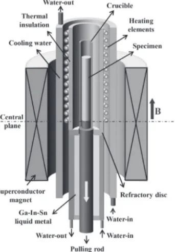
The details of the Bridgman apparatus in the high magnetic
field are shown in Fig. 1. The superconducting magnet can produce an axial static magnetic field with an adjustable intensity up to 6 T. The heating element is a cylindrical silicon carbide tube. Temperature gradient is controlled by adjusting the temperature of the hot zone. DS was conducted by pulling the crucible assemblies downward. All alloy rods were directionally solidified without magnetic field at first. The axial orientation near the end of solidified rod was examined. If the dendrite array was the©001ªcrystallographic direction, the rod was selected as a seed. Then, the seed was place into the corundum and carefully positioned in the furnace to ensure that only part of it melted in order to preserve the axial©001ªorientation. The crucible assemblies were solidified again under various temperature gradients and magneticfields at afixed pulling rate (v=50 µm s¹1). After desired length solidified, quenching was carried out by quickly withdrawing the specimen into a water-cooled cylinder containing Ga-In-Sn liquid metal.
The transverse sections of the solidified samples were mechanically ground and electrolytic polished. Microstruc-tures were revealed by Leica DM6000 optical microscope (OM) after etching in a dilute HF solution (0.5% HF). Electron back-scattering diffraction (EBSD) measurements were carried out using an Apollo 300 SEM microscope equipped with an Oxford Nordlys detector. The recording and +1Graduate Student, Shanghai University
indexing of the pseudo-Kikuchi lines was performed by the software Channel5 from HKL Technology.
3. Results
[image:2.595.337.516.70.388.2]3.1 Observation of stray grains in DS samples
Figure 2 shows transverse microstructures and orientations of the samples directionally solidified under various magnetic
fields at the temperature gradient of 27 K cm¹1. Under the magnetic fields of 0 and 2 T, the axial orientations of the dendrite arrays locate around ©001ª direction and no stray grains emerge (Fig. 2(a) and (b)). In the magneticfield of 4 T, two stray grains occur (marked 2 and 3 in Fig. 2(c)). When the magnetic field increases to 6 T, four misaligned grains (marked 2, 3, 6 and 7 in Fig. 2(d)) are observed. The orientations of grains marked 2, 6 and 7 lie closely to©310ª direction. These results indicate that stray grains are inclined to form in higher magnetic fields (>2 T). Figure 3 exhibits the grain morphology on the longitudinal sections correspond to Fig. 2(a) and (d). Without magnetic field, the ©001ª dendrite trunks are well aligned to the temperature gradient. In the presence of 6 T magnetic field, stray grains appear at the edge of the mould wall. The favored growth direction of the stray grains is not parallel to the heatflow. On the other hand, the sidebranches in the region between the two primary trunks become quit irregular than that of no magnetic field. Figure 4 presents the transverse sections of the samples directionally solidified at higher temperature gradients under 6 T magnetic field. When the temperature gradient increases to 65 K cm¹1and 101 K cm¹1, the formation of stray grains is suppressed and the dendrite arrays exhibit axial ©001ª orientation inherited from seed. The results suggest that the formation of misaligned grains is not favored at higher temperature gradient if the intensity of magnetic field is
fixed.
3.2 Evolution of stray grains during DS
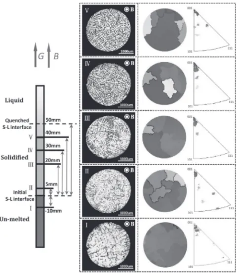
To examine the evolution of the stray grains, OM observation and EBSD analysis at different distances along the growth direction of a sample were performed. The results are shown in Fig. 5. In section I, it could be observed that the orientation of the seed crystal is ©001ª crystallographic direction. The small size grains with random orientation at the edge of the seed crystal are due to the freezing of melt fell into the gap between the seed and crucible wall. At initial pulling stage, four stray grains appear in section II. These
Fig. 2 Transverse microstructures of directionally solidified samples under different magneticfields: (a) 0 T, (b) 2 T, (c) 4 T, (d) 6 T. The temperature gradient isG=27 K cm¹1. The stray grains are outlined by dash lines and their orientations are shown in the corresponding inverse polefigures. The direction of the inverse polefigures refers to the magneticfield.
Fig. 3 Longitudinal microstructures of the directionally solidified samples: (a) without and (b) with a 6 T magneticfield. The temperature gradient is
G=27 K cm¹1. The stray grains are outlined by dash lines. Fig. 1 Schematic diagram of directional solidification apparatus in the high
[image:2.595.85.256.72.318.2] [image:2.595.318.534.468.602.2]grains are randomly oriented and have no orientation relationship with the seed. As growth proceeds, these stray grains are overgrown by [001] dendrites from the seed and only one stray grain survives in section III. However, at the distance of 30 mm from initial solid-liquid interface (section IV), a new stray grain colored yellow emerges near the center of the cross-section. Finally, in section V, several stray grains are observed at the perimeter of the sample. These experimental results show that the stray grains in the later growth stage of the sample is not linked to the anomaly grains formed at the beginning of solidification.
3.3 Orientation relationship between the stray grains and dendrite array
It is noted that the orientation of the new formed stray grains in the upper section of the sample are not totally random, but tend to align their ©310ª crystallographic axis to the magnetic field (Fig. 2(c) and (d)). With the aim of exploring the origin of these grains, grains 4 and 6 in Fig. 2(d) are selected to identify the orientation relationship. Figure 6(a) shows the position of the two grains in the cross section of the sample. As can be seen, the dot of [001] dendrite trunk direction of grain 4 is in the center of the ©001ªpole
figure; the points that represent the [100] and [010] secondary arms are located at the circumference. The overlapping of pole points of grain 4 and 6 in the blue circle indicates that grain 6 stems from the secondary arm of grain 4 (see Fig. 6(b)). Meanwhile, the points in ©013ª pole figure shows the orientation change of the stray grain as marked by the blue arrows. One of the pole points of the grain 6 lies on the center of ©013ª pole figure (see Fig. 6(c)). This means that ©310ª direction of grain 6 aligns to the direction of magneticfield.
4. Discussions
During DS, the existence of inoculants in melt often leads to heterogeneous nucleation of stray grains.14,15) Since the samples are obtained by melting high purity alloy, the precipitation of these particles is not favored. Besides, the heterogeneous nucleation would happen on mould wall, especially at the beginning of DS process. Stanford et al.7)
pointed out that this grain defects occurred only over a distance of 2 mm in the growth direction; after this distance no further nucleation is observed. This is agreement with our observation that the number of misaligned grains is decreased as the solidification front advanced from section II to III (see Fig. 5). From Fig. 5, we can alsofind that the stray grains in section IV have no orientation relationship with the defect grains in section II. It can be concluded that the stray grains formed under high static magnetic field is not due to the heterogeneous nucleation. On the other hand, the detachment of dendrite arms is accepted for stray grain formation.16,17)As mentioned above, the EBSD analysis suggests that the stray grains initiate from the secondary arms. Secondly, the size of some stray grain (grain 3 in Fig. 2(c)) is comparable with the diameter of the secondary arm. At last, in the presence of the high magnetic field, the sidebranches in the interdendritic region are seriously distorted (Fig. 3(b)). Therefore, it is suggested that the high magneticfield exerts great impact on the sidebranches and promotes the detachment.
Fig. 4 Transverse microstructures of directionally solidified samples under different temperature gradients: (a) 65 K cm¹1, (b) 101 K cm¹1. The intensity of magneticfield isB=6 T. The direction of the inverse pole
figures refers to the magneticfield.
[image:3.595.66.271.69.241.2] [image:3.595.302.546.70.162.2] [image:3.595.50.290.305.581.2]The pile-up of rejected solute has been proved to trigger sidebranch fragmentation.18) Since distribution of solute element is affected by convective mass transport, the detachment behavior of sidebranch would be affected by the fluid flow. When a conductive crystal grows in DS assemblies, the difference of Seebeck coefficients between the solid and liquid phases will induce thermoelectric currents (TEC). When a static magnetic field is imposed, the Lorentz force is created by the interaction of the TEC and the field. This is the thermoelectric magnetic effect. The Lorentz force will drive melt motion, i.e., the thermoelectric magnetic convection (TEMC).19) If the columnar dendrite well aligns to the magneticfield, the TEMC is a vortex and
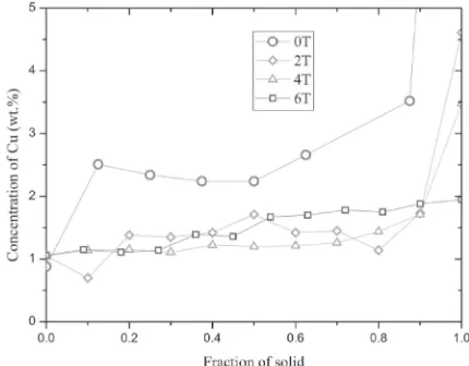
[image:4.595.128.467.70.201.2]flows in the plane perpendicular to the primary trunk. Figure 7 shows the dendrite morphologies in the trans-verse sections without and with a 6 T magnetic field at the temperature gradient of 27 K cm¹1. The TEMC causes high-order sidebranch in upstream direction to grow faster than the downstream side, which lead to a pinwheel-like pattern.20) This morphology change proves the existence of the TEMC around the columnar dendrite and the TEMC is not damped up to 6 T magnetic field. The stirring effect by the TEMC could reduce the solute build-up. To confirm this, Energy Dispersive Spectrometer (EDS) was applied to measure the solute microsegregation in interdendritic region. The meas-urements were carried out along secondary dendrite arms in the transverse sections. As shown in Fig. 8, the interdendritic solute accumulation is reduced in magnetic field. Therefore, the likelihood of fragment formation due to solute enrichment is reduced by the TEMC.
The mechanical loading also plays a substantial role in dendrite fragmentation.21) As mentioned above, due to thermoelectric magnetic effect, Lorentz force exists in solid. We term the Lorentz force acted on solid “thermoelectric magnetic force (TEMF)”. The amplitude of the TEMF is written as:22)
fTEMF¼· ·L·SfL
LfLþ·SfSðSsSLÞGB ð1Þ
where ·S, ·L are the electric conductivities of the solid and liquid phases; fS,fL the solid and liquid fractions;SSand SL are the Seebeck coefficients of the solid and liquid phases, respectively,Bis the magneticfield andGis the temperature gradient. When the columnar dendrite well aligns to the direction ofG, the thermoelectric current in the primary trunk
is nearly parallel toBand no Lorentz force is generated. On the other hand, the thermoelectric current around the primary trunk is not parallel to the magneticfield. This is proved by the existence of the TEMC. The secondary dendrite arms in mushy zone will suffer the TEMF. The integrity of these forces could impose a torque on the columnar dendrite. Since the TEMF is a body force, the magnitude of the torque is proportional to the volume of the sidebranches. The volume of a fully developed secondary arm is:
V1¼ ³d2
2
L1 ð2Þ
where d and L1 are the diameter and the length of the secondary dendrite arm, respectively. L1 is equal to half of primary dendrite spacing. For a fixed pulling speed, L1 is written as:
L2¼k1G1=2 ð3Þ
where k1is a constant number for a fixed pulling rate. The number of the secondary arms n could be expressed as
n=4L0L2¹1. TheL0 is the length of mushy zone:
L0¼T G1 ð4Þ
where the¦Tis the temperature interval between the solidus and the liquidus. The secondary arm spacingL2is:2)
Fig. 7 Evolution of the tertiary sidebranch in the plane perpendicular to the primary trunk: (a) without and (b) with a 6 T magneticfield. The samples were directional solidified atG=27 K cm¹1.
Fig. 8 Microsegregation profiles of the Al-4.5 mass%Cu alloys under various magneticfields. The samples were directional solidified atG=
[image:4.595.318.533.253.421.2]L2 ¼k2G2=3 ð5Þ
Wherek2is the constant number for afixed pulling rate. The force acted on the secondary arms is:
F¼fTEMFV ¼nfTEMFV1 ð6Þ
The torqueMton the primary trunk is:
Mt¼FD2 ð7Þ
whereDis the diameter of the primary trunk. The maximum shear stress¸maxis:
¸max¼16M³D3t ð8Þ
As a result, the primary trunk would be twisted by this shear stress.
In dendrite network, further twisting of the columnar dendrite will be impeded by the neighboring dendrites or crucible wall. Then, the TEMF imposed on the whole columnar dendrite will concentrate and induce bending moment M2 in secondary dendrite arms. This bending moment is expressed as:
M2¼FL1 ð9Þ
For afixed pulling rate, this bending moment is proportional toBG¹5/3as deducing from above by using the relationship
D=d=0.31L2.23) Finally, the secondary arm can be pinched-off to form stray grain. This is the reason why strays are preferred to form as the intensity of magneticfield enhanced (Fig. 2), while not be favored for high temperature gradient (Fig. 4). This mechanism is schematically illustrated in Fig. 9.
When the fragments are formed, they will not settle to the bottom of the interdendritic region due to an upwardflow.24) This flow is a counter flow of the TEMC. As the fragments
floated in melt, they will undergo a magnetic torque¥caused by the magnetic anisotropy of the aluminum crystal:25)
¼2®» 0B
2Vsin 2ª ð10Þ
where "» the difference of the susceptibilities of two crystallographic directions,®0the permeability in a vacuum,
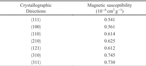
B magnetic field, V the volume of the crystal, ª the angle between the magnetic field B and the crystallographic direction of the greatest susceptibility. If the crystal can rotate freely, its crystallographic axis of largest susceptibility will align to the direction of the magnetic field. Zhu26) measured the magnetic susceptibility of various crystallo-graphic axes of aluminum crystal (shown in Table 1) and found that the ©310ª direction exhibited the maximum magnetic susceptibility. This result illustrates why the stray grains usually align the ©310ª direction along the magnetic
field.
5. Conclusions
The formation behaviors of stray grains in directionally solidified Al-4.5 mass% Cu alloys under an axial high magnetic field are studied. The following conclusions could be made.
(1) The emergence of stray grains during DS is associated with the detachment of secondary dendrite arms. The number of stray grains is significantly affected by the intensity of magnetic field and temperature gradient. Low temperature gradient and high magnetic field is favored for stray grain formation.
(2) The application of high magnetic field could alter the
[image:5.595.127.468.70.237.2]Fig. 9 Schematic illustration of the bending moment in the secondary dendrite arm: (a) the primary trunk is twisted by the torque which arises from the TEMF acted upon the columnar dendrite; (b) and (c) the impediment of further twisting of the columnar dendrite leads to a bending moment in a secondary arm.
Table 1 The magnetic anisotropy of pure aluminum crystal.26)
Crystallographic Directions
Magnetic susceptibility (10¹6cm3g¹1)
©111ª 0.541
©100ª 0.561
©110ª 0.614
©210ª 0.625
©121ª 0.612
©310ª 0.745
[image:5.595.306.549.313.424.2]crucible wall arises bending moment on secondary arms and leads to fragmentation.
(4) After the fragments are formed, they will align their ©310ªdirection to magnetic field due to the maximum value of magnetic susceptibility in this crystalline direction of¡-Al crystal.
Acknowledgments
This work is supported by the National 973 Project (No. 2011CB610404), the Shanghai Committee of Science and Technology (No. 13DZ1101102, 13521101102 and 14521102900), and the Natural Science Foundation of China (No. 51404148 and 51401116).
REFERENCES
1) B. Chalmers:Principles of Solidification, (John Wiley & Sons, New York, 1964) pp. 116120.
2) W. Kurz and D. J. Fisher:Fundamentals of Solidification, (Trans Tech Publications, Switzerland, 1986) pp. 79.
3) J. P. Poirier: Creep of Crystals: High-Temperature Deformation Processes in Metals, Ceramics and Minerals, (Cambridge University Press, New York, 1985) pp. 170171.
4) X. B. Meng, Q. Lu, X. L. Zhang, J. G. Li, Z. Q. Chen, Y. H. Wang, Y. Z. Zhou, T. Jin, X. F. Sun and Z. Q. Hu:Acta Mater. 60(2012) 39653975.
9) Y. Z. Zhou:Scr. Mater. (2011) 281284.
10) Z. H. I. Sun, X. Guo, M. Guo, J. Vleugels, O. Van der Biest and B. Blanpain:J. Alloy. Compd.551(2013) 568577.
11) C. Gerber, D. Anselmetti, J. G. Bednorz, J. Mannhart and D. G. Schlom:Nature350(1991) 279280.
12) Y. Kawase, Y. Nakamura, T. Izumi, K. Murata and Y. Shiohara:Phys. C 357360(2001) 673676.
13) X. Li, Z. M. Ren, G. H. Cao, Y. Fautrelle and C. Esling:Acta Mater.59 (2011) 62976307.
14) H. Jung, N. Mangelinck-Noel, C. Bergman and B. Billia:J. Alloy. Compd.477(2009) 622627.
15) D. A. Pineda and M. A. Martorano:Acta Mater.61(2013) 17851797. 16) K. A. Jackson, J. D. Hunt and D. R. Uhlmann: Trans. Metall. Soc.
AIME263(1966) 149.
17) H. Yasuda, I. Ohnaka, K. Kawasaki, A. Suglyama, T. Ohmichi, J. Iwane and K. Umetani:J. Cryst. Growth262(2004) 645652. 18) D. Ruvalcaba, R. H. Mathiesen, D. G. Eskin, L. Arnberg and L.
Katgerman:Acta. Mater.55(2007) 42874292. 19) J. A. Shercliff:J. Fluid. Mech.91(1979) 231251.
20) R. Tönhardt and G. Amberg:J. Cryst. Growth194(1998) 406425. 21) S. Ananiev, P. Nikrityuk and K. Eckert:Acta Mater.57(2009) 657
665.
22) P. Lehmann, R. Moreau, D. Camel and R. Bolcato: Acta Mater.46 (1998) 40674079.
23) Y. Miyata, T. Suzuki and J. I. Uno:Metall. Mater. Trans. A16(1985) 17991805.
24) A. Kao and K. Pericleous: Int. Conf. on Modeling of Casting, Welding and Advanced Solidification Processes33(2012) p. 012045. 25) T. S. Suzuki, T. Uchikoshi and Y. Sakka:Sci. Technol. Adv. Mater.7
(2006) 356364.