Early-Stage Recrystallized Grains in Copper Single Crystals Deformed in Tension
along
<
111
>
Direction
Tatsuya Okada
1, Hirofumi Tai
2,*and Minoru Tagami
11Institute of Science and Technology, Tokushima University, Tokushima 770–8506, Japan
2Graduate School of Advanced Technology and Science, Tokushima University, Tokushima 770–8506, Japan
The objective of the present study was to characterize early-stage recrystallization in copper single crystals. Two crystals with different front surfaces, i.e., {110} or {112}, were deformed in tension along the <111> direction to a tensile strain of 0.2. The deformation was uniform without deformation bands. Thin disk specimens prepared from the deformed <111>{110} and <111>{112} crystals were heated in a high vac-uum to a set temperature with a holding time of 10 s, and subsequently observed. This process was repeated by raising the heating temperature for each step until the first detection of recrystallized grains. In all specimens, recrystallization was found after annealing at almost the same temperature, about half of the melting point in the absolute temperature scale. Each recrystallization aggregate was composed of a pair of major recrystallized grains with a coherent twin boundary. Small annealing twins were detected inside the larger recrystallized grains but not in the smaller grains. The present results suggest that recrystallization in copper begins with the formation of pairs of twin-related recrystallized grains, followed by the introduction of annealing twins. [doi:10.2320/matertrans.M2016455]
(Received December 20, 2016; Accepted January 30, 2017; Published March 3, 2017)
Keywords: copper, single crystal, tensile deformation, recrystallization
1. Introduction
In a face-centered cubic (FCC) metal single crystal de-formed in tension along a tensile axis lying within the stereo-graphic triangle, the initial slip occurs in the primary slip sys-tem having the largest Schmid factor. As the deformation proceeds, the crystal rotates so that the tensile axis moves
to-wards the <001>-<111> line in the stereographic triangle,
where the conjugate slip system is activated. For a special
tensile axis, e.g., <1 4 10> or <110>, the secondary slip
sys-tem operates in narrow bands to form non-uniformly de-formed regions such as kink bands and bands of secondary
slip1–7). On the other hand, when FCC metal single crystals
are deformed in tension along the <111>, <112> or <001>
direction, multiple glide occurs, where slip systems having the same Schmid factor operate to the same degree from the
initial stage of deformation8–10). As a result, the orientation of
such crystals is practically unchanged from the initial one. Since the rotation of the crystal is negligibly small, a non-uni-formly deformed region is not introduced.
It was reported that work-hardening behaviors of
alumi-num <111>, <112> and <001> crystals are totally different
at room temperature9,10). The nominal tensile stress is the
largest in the <111> crystal followed by the <112> crystal. In
contrast, in the <001> crystal, the stress is apparently
saturat-ed at the nominal tensile strain of 0.1 and larger. This differ-ence is not accounted for by the number of activated slip
sys-tems because eight slip syssys-tems are activated in the <001>
crystal and this is the largest number among these crystals. It is presumed that the work-hardening of the three
multi-ple-glide orientations reflects the difficulty/ease of cross-slip.
Dielh et al.11) calculated the values of τ
c/τp as a function of
the tensile axis for FCC single crystals, where τp is the shear
stress imposed on the primary slip plane and τc is that on the
cross-slip plane. The τc/τp takes the largest number, +1 for
the <001> tensile axis, implying that cross-slip is promoted
in the <001> crystal. The τc/τp is 0 for the <112> axis. It is
expected that cross-slip is the most suppressed in the <111>
crystal because τc/τp takes the smallest number, -1. Tagami et
al.10) discussed the morphological features of slip lines on the
surface and dislocation microstructures in the interior with
respect to the difficulty/ease of cross-slip in aluminum single
crystals of multiple-glide orientation. In the <111> crystal in
which cross-slip is the most suppressed, the dislocation mi-crostructure is composed of a fine cell structure with high-dis-location-density cell walls. The slip morphology is character-ized by finely wavy slip lines as a result of frequent short-dis-tance slip. In contrast, because of the promoted
cross-slip in the <001> crystal, the interior is composed of large
cells with low-dislocation-density cell walls and the surface slip lines clearly show large-step cross-slip. The dislocation microstructures directly affect the recrystallization behaviors in post-deformation annealing. When aluminum single crys-tals of multiple-glide orientation deformed to a tensile strain
around 0.2 were simultaneously annealed, the <111> crystal
was the first to recrystallize, at the annealing temperature of
0.84TM, where TM is the melting temperature in the absolute
temperature scale. The <112> crystal did not recrystallize
un-til 0.94TM, and no recrystallized grain was found in the
<001> crystal even after annealing at 0.97TM.
Compared to the studies on tensile deformation and recrys-tallization of aluminum single crystals, fewer studies have been carried out on copper. One of the reasons is the com-plexity of recrystallized microstructures in copper. For in-stance, the identification of primary recrystallized grains is not easy due to the existence of annealing twins. To overcome
this difficulty, Kato et al.12) carried out annealing experiments
using thin disk specimens prepared from copper single
crys-tals deformed in tension along the <110> direction. They
were successful in detecting early-stage recrystallized grains at the boundary between the deformation matrix and the band of secondary slip. In the present study, we applied their
tech-nique to <111> copper single crystals. As evident from the
*
Graduate Student, Tokushima University, Present address: TADANO Ltd., Takamatsu 761–0185, Japan
aluminum single crystals of multiple-glide orientation, the
work-hardening is the largest for the <111> crystal due to the
suppression of cross-slip. In addition, the cross-slip in copper is more suppressed than that in aluminum because of its low-er stacking fault enlow-ergy. Thlow-erefore, highlow-er-density accumula-tion of dislocaaccumula-tions is expected in copper single crystals
de-formed in tension along the <111> direction, which leads to
recrystallization at relatively lower temperatures in the post-deformation annealing.
The objective of the present study was to characterize the
recrystallized grains formed in copper <111> crystals. We
repeatedly heated thin disk specimens in a high vacuum until early-stage recrystallization was detected.
2. Experimental Procedures
Two samples for tensile deformation were prepared by spark-cutting from copper single crystals grown with the Bridgman method. The purity of the material was
99.99 mass%. The front surfaces of the samples were {110}
and {112}. In the following, the samples are referred to as
<111>{110} and <111>{112}, combining the tensile
direc-tion <111> and front surface notations. After mechanical
pol-ishing, the front surface was finished by electro-polishing in a solution of 30 vol% phosphoric acid in ethanol. As schemati-cally shown in Fig. 1(a), the gauge portion of the samples was
4 × 12 × 4 mm3. A tensile strain of 0.2 was applied at room
temperature with the initial strain rate of 3 × 10⁻⁴ s−1. Slip
lines on the front surface were observed with a scanning elec-tron microscope (SEM). The crystallographic orientation was measured from the electron channeling pattern (ECP). The
electron microscope used for the SEM/ECP analysis was a
JEOL JSM-6400 SEM.
The deformed samples were cut in half along their thick-ness by spark-cutting and subsequently thinned by mechani-cal polishing to a thickness of 0.14 mm. After the surface damage layers were removed by electro-polishing, disk-shaped specimens, 0.12 mm thick and 3 mm in diameter,
were cut from the thinned samples with a mechanical punch. The specimen preparation procedures are schematically shown in Fig. 1(b). The disk specimens were annealed on the heating stage of a transmission electron microscope (TEM) in
a high vacuum with a pressure lower than 2 × 10⁻⁴ Pa. In the
present study, the TEM was used as a high-vacuum furnace. We used thin disk specimens for annealing because the tem-perature was expected to be uniform within a specimen of very small volume. Heating was maintained for 10 s after the stage temperature reached the desired value. This short-term annealing prevented excessive growth of recrystallized grains. It was possible to observe the annealed specimen subsequent-ly by SEM without an etching process owing to the absence of an oxide layer on the surface. We repeated the combination of heating by TEM and subsequent observation by SEM, rais-ing the temperature for each annealrais-ing step until the first de-tection of recrystallized grains. The orientation distribution around the recrystallized grains was analyzed using electron back-scattered diffraction (EBSD) data taken using a TSL
OIM system. The electron microscope used for the SEM/
EBSD analysis was a JEOL JSM-5800 SEM.
3. Results
3.1 Initial orientation
Stereographic projections of <111>{110} and <111>{112}
samples are presented in Fig. 2(a) and (b), respectively. The
Fig. 1 (a) Schematic of a single-crystalline sample for tensile deformation. Tensile axis (T.A.) is parallel to the <111> direction. (b) The deformed sample was cut in half along its thickness and thinned. The disk-shaped specimens for annealing were cut from the thinned sample.
[image:2.595.342.511.421.762.2] [image:2.595.83.254.553.743.2]deviations of the tensile axis and front surface from their
ide-al orientation were less than 1 . Four {111} slip planes (P1 to
P4) and six <110> slip directions (D1 to D6) are represented
using triangular and elliptic symbols, respectively, in Fig. 2.
A bar on the top of a number, e.g., D¯3 , shows that the
direc-tion is opposite that of a number without the bar. Schmid fac-tors of 12 slip systems represented by the combination of slip plane and direction are listed in Table 1.
3.2 Deformation
Both <111>{110} and <111>{112} samples were
uniform-ly deformed without the formation of deformation bands. SEM images taken at the middle of the gauge portion of the
samples are presented in Fig. 3. From the SEM/ECP
analy-sis, it was confirmed that the deviation of the crystallographic orientation from the initial one was less than 2 . In both
sam-ples, slip lines did not fit the traces of slip planes. This is presumably due to fine-scale repeated cross-slips much finer than the resolution of these micrographs.
3.3 Recrystallization in <111>{110} sample
Annealing was carried out for three disk specimens
pre-pared from the deformed <111>{110} sample. A specimen
was heated to a set temperature with holding time of 10 s on the TEM heating stage, naturally cooled down to room tem-perature, and subsequently observed by SEM. This process was repeated by raising the annealing temperature for each step until the first detection of recrystallized grains. In all three disk specimens, recrystallization was first found after
the annealing at 633 K (0.47TM). Recrystallized grains did
not appear as an independent single grain, but always formed an aggregate of several recrystallized grains. Since the objec-tive of the present study was to examine recrystallization at its
early stage, the SEM/EBSD analysis was carried out on the
disk specimen in which the smallest recrystallization
aggre-gates (< 100 μm) were found. Here, we present the results for
a recrystallization aggregate composed of two major recrys-tallized grains with a twin boundary and annealing twins.
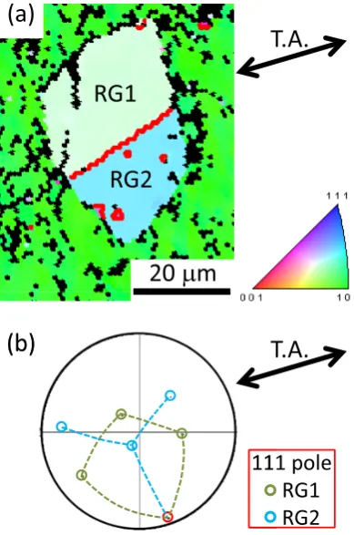
An inverse-pole-figure orientation map of the
recrystal-lized <111>{110} sample is presented in Fig. 4(a); the
color-ing is based on the orientation of the disk surface. As evident from the color key in the figure, the green background clearly shows that the surface of the matrix is practically unchanged
from the initial {110} plane. In the construction of the
orienta-tion map, we only used data having credibility indices higher than 0.1. The black points in the matrix with low credibility indices presumably correspond to regions of high dislocation density because distorted EBSD patterns leading to analytical errors are likely to be obtained from such regions. The recrys-tallization aggregate consists of two major recrystallized grains, i.e., RG1 and RG2. In the orientation map, boundaries between the regions of ∑3 relationship (e.g., 60 rotation
around a <111> axis) are represented by thick red lines.
Hence, the boundary between RG1 and RG2 is a ∑3 bound-ary. The 111 pole figure constructed from the orientation data of RG1 and RG2 is presented in Fig. 4(b). The common 111 pole of the two grains is represented by a red circle. It is sug-gested that the boundary between RG1 and RG2 is a coherent
twin boundary from the fact that the trace of the {111} plane
corresponding to the common 111 pole (red circle in Fig. 4(b))
agrees with the ∑3 RG1/RG2 boundary in Fig. 4(a). In
addi-tion to the ∑3 boundary between RG1 and RG2, several red lines surrounding small areas are observed inside RG1 and RG2. They are presumably annealing twins and can be ex-pected to grow as the annealing continues, leading to the for-mation of a more complex aggregate of recrystallized grains, often observed in well-developed recrystallized microstruc-tures in copper.
3.4 Recrystallization in <111>{112} sample
Annealing was carried out for three disk specimens
pre-pared from the deformed <111>{112} sample. A combination
of heating on the TEM stage and subsequent observation by SEM was repeated, raising the annealing temperature for each step until the recrystallized grains were first detected at 623 K (0.46TM). We should note that in spite of the different Table 1 Schmid factors of slip systems.
Slip plane Slip direction <111>{110} crystal <111>{112} crystal
P1 D1 0.28 0.28
D3 0.28 0.28
D4 0 0
P2 D2 0 0
D4 0 0
D5 0 0
P3 D2 0 0
D3 0.28 0.26
D6 0.28 0.27
P4 D1 0.27 0.27
D5 0 0
D6 0.27 0.26
[image:3.595.54.289.297.751.2] [image:3.595.46.291.298.466.2]sample surface, recrystallization occurred at almost the same
annealing temperature in both <111>{110} and <111>{112}
samples. Recrystallized grains appeared as aggregates. In the following, we report on the recrystallization in one of the disk specimens, in which the smallest recrystallization aggregates
(< 100 μm) were found.
An inverse-pole-figure orientation map of the
recrystal-lized <111>{112} sample is presented in Fig. 5(a) with
color-ing based on disk surface orientation and points with low
credibility indices (< 0.1) presented as black. The purple
background clearly shows that the surface of the matrix is
practically unchanged from the initial {112} plane. There are
two pairs of major recrystallized grains, i.e., RG3/RG4 and
RG5/RG6. The 111 pole figures for the pairs are presented in
Fig. 5(b) and (c). In the pole figures, the common 111 pole for
both grains is drawn with a red circle. As with the RG1/RG2
boundary in Fig. 4, it appeared that the ∑3 boundary in each pair was a coherent twin boundary. Annealing twins, i.e., small areas surrounded by a red line, are recognized only in-side the larger grains, i.e., RG5 and RG6. No annealing twin is found in the smaller RG3 and RG4.
3.5 Orientation relationship
Comparing the orientations of paired recrystallized grains, we notice that the coherent twin boundary in each pair is al-most perpendicular to the sample surface. Among the three pairs, the largest deviation from the perpendicular position is
found in the boundary between the RG5/RG6 pair [Fig. 5(c)]
but less than 10 . It is suggested that the coherent twin bound-ary between the major recrystallized grains is chosen so that
the boundary area is minimized.
The orientations of the six recrystallized grains observed in the present study were compared with those of their matrixes, paying attention to the orientation relationship described by a
rotation about low-index axis, i.e., <001>, <011> or <111>.
Two recrystallized grains, i.e., RG2 in the <111>{110}
sam-ple and RG3 in the <111>{112} sample, showed a <001>
-ro-tation relationship with the matrix. The ro-ro-tation angle was 30 for RG2 and 20 for RG3. The 001 pole figures for RG2 and RG3 are presented in Fig. 6(a) and (b), respectively. Other grains did not have an orientation relationship that could be described by rotation about a low-index axis.
The orientation relationships in the present results differ from those in uniformly deformed aluminum single crystals. In aluminum single crystals annealed as a bulk sample, 70% Fig. 5 (a) SEM/EBSD inverse-pole-figure orientation map of the area
con-taining two pairs of major recrystallized grains (RG3/RG4 and RG5/ RG6) in the annealed <111>{112} specimen. The 111 pole figures are presented in (b) RG3/RG4 and (c) RG5/RG6. The common 111 pole is represented by a red circle.
[image:4.595.323.522.68.526.2] [image:4.595.71.266.69.363.2]to 80% of recrystallized grains had <111>-rotation relation-ships with the matrix, and the rotation angles were in the
range of 20 to 50 9,10). For aluminum, detailed analyses of
many recrystallized grains have led to the proposal of a dislo-cation model of recrystallization at the intersection of slip
bands13). Although the present results suggest that the lower
stacking fault energy and the resultant extended dislocations in copper play an important role in determining the rotation axes, we reserve final judgment as to whether the present re-sults are essential to copper until analysis of orientation data for a much larger number of recrystallized grains at the early stage.
4. Discussion
In the present study, we found three recrystallization agggates that were composed of pairs of twin-related major re-crystallized grains. The paired rere-crystallized grains of similar size were bounded by a coherent twin boundary, and small annealing twins were observed in the larger grains. On the other hand, the smaller grains, i.e., RG3 and RG4, did not contain annealing twins. The above results suggest that at the early stage of recrystallization in copper, a pair of twin-relat-ed grains is formtwin-relat-ed, and annealing twins are subsequently introduced with the growth of recrystallized grains.
From an energetic viewpoint, the introduction of disloca-tion-free recrystallized grains into a plastically deformed ma-trix is similar to the inclusion problem in the micromechan-ics. The present recrystallization problem can be resolved into the following steps. First, a part is virtually cut from the dislocated matrix. Then the part is made dislocation-free and
rotated with respect to the matrix about an axis (e.g. <100>
axis in the present case) by an angle of 20 or 30 . Finally, the part is brought back into the hole from which the part was cut. The above process produces the increase in elastic strain en-ergy.
The elastic strain energy of the inclusion composed of twin-related grains for an iron inclusion in a copper matrix
was calculated by Mura et al.14) They clearly showed that the
strain energy associated with martensite transformation is re-duced by the introduction of a twinned structure into an iron inclusion. Compared to the single-domain martensite inclu-sion, the strain energy is reduced by more than 30% by the introduction of the first twin. The strain energy is further re-duced by the introduction of additional twinned structures,
although the energy reduction becomes smaller14). Similarly,
in the recrystallization in copper, it is expected that a pair of twin-related recrystallized grains is energetically more favor-able than a single independent grain. More strain-energy re-duction is expected by the further introre-duction of annealing twins parallel to the original twin boundary. In another study of a copper single crystal deformed in tension along the
<110> direction, a recrystallization aggregate composed of
three pairs of twins, each parallel to the other, was found at the boundary between the deformation matrix and the band of
secondary slip12).
We should be careful in applying the elastic energy argu-ment of martensite transformation of a spherical inclusion inside an infinite matrix to the present recrystallization prob-lem because in our case recrystallization occurs at the sur-face, resulting in only semi-spherical recrystallized grains, and the strain energy calculation was made on the assumption of elastic isotropy. However, the elastic theory provides a new perspective on the early stage of recrystallization.
5. Summary
Annealing experiments were carried out for thin disk
spec-imens prepared from <111>{110} and <111>{112} copper
single crystals deformed in tension. In all specimens, post-an-nealing recrystallization was first observed at almost the same temperature, about half of the melting point. Crystallographic orientation was analyzed for three pairs of major recrystal-Fig. 6 The 001 pole figures represent the orientation of (a) RG2 in the
[image:5.595.80.255.70.551.2]lized grains with the SEM/EBSD method. The paired recrys-tallized grains had a coherent twin boundary, i.e., a ∑3 (111) boundary. Small annealing twins were found inside only the larger recrystallized grains; no annealing twins were observed in the smaller recrystallized grains. The above results suggest that recrystallization in copper begins with the formation of pairs of twrelated recrystallized grains, followed by the in-troduction of annealing twins.
REFERENCES
1) R.W.K. Honeycombe: J. Inst. Met. 80 (1951–52) 45–56.
2) K. Higashida, J. Takamura and N. Narita: Mater. Sci. Eng. 81 (1986) 239–258.
3) F. Inoko and K. Kashihara: Mater. Sci. Forum 113–115 (1993) 139– 144.
4) K. Kashihara, M. Tagami and F. Inoko: Mater. Trans., JIM 37 (1996)
564–571.
5) J.A. Wert, X. Huang and F. Inoko: Proc. R. Soc. Lond. A 459 (2003) 85–108.
6) T. Okada, X. Huang, K. Kashihara, F. Inoko and J.A. Wert: Acta Mater.
51 (2003) 1827–1839.
7) J.A. Wert, K. Kashihara, T. Okada, X. Huang and F. Inoko: Philos. Mag. 85 (2005) 1989–2006.
8) T. Takeuchi: Trans. JIM 16 (1975) 629–640.
9) K. Kashihara, M. Tagami, T. Okada and F. Inoko: Mater. Sci. Eng. A
291 (2000) 207–217.
10) M. Tagami, K. Kashihara, T. Okada and F. Inoko: Mater. Trans. 42 (2001) 2013–2020.
11) J. Diehl, M. Krause, W. Offenhäuser and W. Staubwasser: Z. Metallk.
45 (1954) 489–492.
12) S. Kato, K. Ootsubo, T. Ueki and T. Okada: J. Jpn. Inst. Met. Mater. 77 (2013) 101–106.
13) F. Inoko, K. Kashihara, M. Tagami and T. Okada: Mater. Trans. 51 (2010) 597–606.