Multiscale Characterization of a Polycrystalline Aggregate Subjected
to Severe Plastic Deformation with the Finite Element Method
Ikumu Watanabe
1and Daigo Setoyama
21National Institute for Materials Science, Tsukuba 305–0047, Japan 2TOYOTA Central R&D Labs., Inc., Nagakute 480–1118, Japan
The heterogeneous deformation of a polycrystalline aggregate under severe plastic deformation was reproduced with finite element anal-ysis by using single-crystal plasticity to characterize the evolution process of the heterogeneity. Finite element analyses of a periodic polycrys-talline aggregate were carried out to simulate the deformation process corresponding to the multi-pass equal-channel angular extrusion process, which reached over 250% of the macroscopic logarithmic accumulated plastic strain. The numerical results were analyzed from multi-scale perspectives: the macroscopic response, evolution of the crystallographic orientation, and deformation state of the microstructure. This study addressed the importance of finite element discretization to reproduce the heterogeneous deformation of a polycrystalline aggregate, including that of the inside grains, which is a key element for investigating the underlying fine-graining mechanism.
[doi:10.2320/matertrans.MH201514]
(Received March 15, 2016; Accepted May 12, 2016; Published June 24, 2016)
Keywords: finite element analysis, crystal plasticity, severe plastic deformation, texture
1. Introduction
Fine-graining is currently a recognized strategy for im-proving the material properties in metals. It differs from the conventional materials design methodology by only adding alloy elements. A standard approach to fabricating fine-grain metals is to impose a severe plastic deformation (SPD) to a metallic material. This is typically done by shape-preserving deformation processes, such as equal-channel angular extru-sion (ECAE)1,2), high-pressure torsion (HPT)3), and accumu-lative roll bonding (ARB)4,5). Hence, fine-graining is a strate-gy for process-oriented material research and development.
Computer-aided engineering (CAE) technologies, of which the finite element (FE) method is representative, have been employed to simulate and optimize metal-forming processes in industry. These computational approaches have been ap-plied to SPD processes6–8). Recently, CAE technologies have also been applied to investigating the deformation mecha-nism at the micro-scale. FE analysis using a constitutive mod-el of a single crystal, which is commonly known as the crystal plasticity finite element method (CPFEM), has drawn a great deal of attention as a cross-disciplinary research field be-tween mechanics and metallurgy9,10). Advanced crystal plas-ticity models have been developed to describe the strengthen-ing effect of fine-grainstrengthen-ing on the basis of dislocation theo-ry11,12). In addition, polycrystal plasticity models have been coupled with homogenization theories and the constitutive model of a single crystal to estimate the evolution of a crys-tallographic texture corresponding to a metal-forming pro-cess. Homogenization theories are classified according to the resolution of the microstructural representations. Mean-field theories13,14) and self-consistent theories15,16) are based on full-analytical and semi-analytical homogenization theories in which the crystal grains are modeled as a homogeneous body. Beyerlein et al.17–19) applied a self-consistent theory to investigate the evolution of the crystallographic texture under the ECAE process. They pointed out that a standard self-con-sistent theory has conceptual limitations with regard to the reproducibility of the crystallographic texture after
multi-pass ECAE; a grain co-orientation model20) is required to ob-tain a better deformed texture within the framework of self-consistent theories. Within computational discretization approaches based on the homogenization theory, of which the FE method is representative, the deformation state of the mi-crostructure is considered in addition to the macroscopic re-sponse and evolution of the crystallographic texture21,22). Here, the heterogeneous deformation of the inside grains is explicitly treated. The interaction between neighboring grains leading to grain co-orientation behavior can be considered within such computational discretization approaches to de-scribe the morphology of the polycrystalline aggregate, in-cluding the inside crystal grains. However, fine discretization of the inside grains is definitely required in order to discuss the deformation mechanism caused by heterogeneous defor-mations in the microstructure, such as grain sub-division and fine-graining. Although such computational approaches have the potential to characterize the heterogeneous deformation process of a microstructure subjected to SPD, application studies on SPD problems in this field remain an issue owing to the high computational costs.
This study used computational simulations of a polycrys-talline aggregate subjected to SPD to investigate the hetero-geneous deformation of the microstructure, including inside grains, and its evolution from multiscale perspectives: the macroscopic response, evolution of the crystallographic ori-entation, and deformation state of the microstructure. First, numerical simulations corresponding to multi-pass ECAE were carried out to reproduce the evolution of the deformed microstructure; the macroscopic deformation state of sin-gle-pass ECAE was repeatedly imposed upon a polycrystal-line aggregate to obtain a deformation microstructure having over 250% of the macroscopic logarithmic accumulated plas-tic strain. The difference between the B and C routes of ECAE was addressed. Finally, the reproducibility of the heteroge-neous deformation of inside grains by using a FE model dis-cretized with a fine mesh was considered.
Bridging the microstructure and bulk property is a classical research field in continuum mechanics, where the bulk prop-erty is estimated from averaging the state of the microstruc-ture. In such homogenization approaches, the microstructure is modeled as a representative volume element (RVE), or a representative part of the objective microstructure. In compu-tational approaches22,23), the RVE is usually assumed to be a periodic microstructure, and the boundary value problem of the RVE is formulated as
ΩY
P :∇Yη(1)dΩY=0 ∀η(1)∈Wperiodic, (1)
where Y is the coordination system on a micro-scale, P is the first Piola–Kirchhoff stress, η(1) is the variation in the period-ic displacement u(1), dΩ
Y denotes the differential volume of
the overall RVE ΩY, and Wperiodic is the Sobolev space of the periodic function. The displacement field (w) on a micro-scale is defined as w = ¯H Y + u(1), where ¯H is the macroscopic dis-placement gradient. Then, the disdis-placement gradient (H) on a micro-scale is given as
H=∇Yw= ¯H+∇Yu(1), (2)
where ∇Y is the gradient operator. The macroscopic stress is
defined as the volume average of the corresponding micro-scopic variable in the overall RVE.
¯P := 1 ΩY ΩY
PdΩY. (3)
Following the definition of periodicity and eq. (2), the dif-ference in displacements at points A and B that satisfies the periodicity is written as follows:
wA−wB = ¯H(YA−YB). (4)
Equation (4) relates the macroscopic displacement gradient ¯H to the displacement field w on a micro-scale. By using eqs. (3) and (4), FE analysis of the periodic microstructure is carried out by controlling the macroscopic displacement gra-dient ¯H or macroscopic stress ¯P .
2.2 Constitutive model of a single crystal
The heterogeneity of a polycrystalline aggregate is defined by the anisotropy of a crystal grain and its orientations. The anisotropic mechanical behavior of a crystal grain is charac-terized by an elastoplastic constitutive model of a single crys-tal.
2.2.1 Constitutive model of a single crystal
In metallic materials, the elastic deformation is generally small enough that the elastic response can be regarded as lin-ear. Anisotropic linear elasticity can be employed to describe the elastic deformation. Based on the multiplicative
decom-For the plasticity of a single crystal, the anisotropic plastic deformation is characterized by slip systems dependent on the crystal structure. The yield function of the α-th slip sys-tem is defined in a strain-rate-independent format as follows:
φ(α) :=|τ(α)| −q(α)≤0, (6)
where τ (α) is the stress norm and q(α) is the relevant yield stress, including the plastic hardening. The stress norm, which is generally called the resolved shear stress, is defined at the intermediate configuration as
τ(α) := FeTFeˆS : s(α)0 ⊗m(α)0 (7) where s(α)
0 and m(α)0 represent the slip direction vector and nor-mal vector, respectively, of the slip surface of the α-th slip system at the intermediate configuration. nslip is the number of the slip systems. For the plasticity of a single crystal, the crystal lattice does not rotate with the slip deformation. Then, the vectors of the slip system at the current configuration can be denoted as s(α) = Fes(α)
0 and m(α) = Fe−Tm(α)0 . Here the fol-lowing evolution equation of the plastic deformation gradient Fp is employed:
˙Fp Fp−1=
nslip
α=1
γ(α)sign τ(α) s0⊗m0, (8)
where γ(α) is a plastic flow of the active slip system α. The slip history variable is defined as the time integration of the flow, that is,
ξ(α)= t
0 γ
(α)dt ∀α∈[1,n
slip]. (9)
In this study, the yield stress, or critical resolved shear stress, was defined phenomenologically as a nonlinear func-tion of the slip history variables ξ(1),· · ·, ξ(nslip) :
q(α):=τ(α) 0 +δτ(α)
1−exp
−h
(α) 0 δτ(α)
nslip
β=1 Ωαβξ(β)
, (10)
where τ(α)0 , δτ(α), h(α)0 , and Ωαβ are material constants.
In this study, exponential mapping using the evolution law of the elastic/plastic deformation gradient and a generalized inverse matrix on an implicit stress-update algorithm were employed for efficient and robust FE simulations23,24). 2.2.2 Model settings
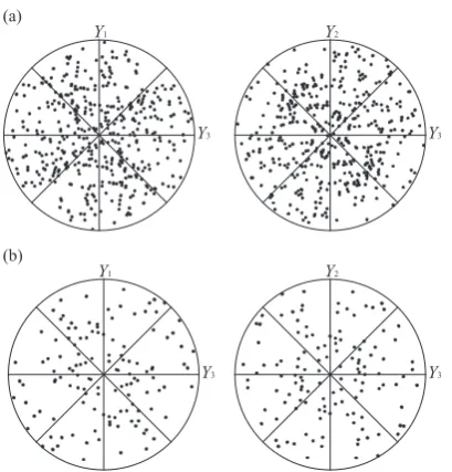
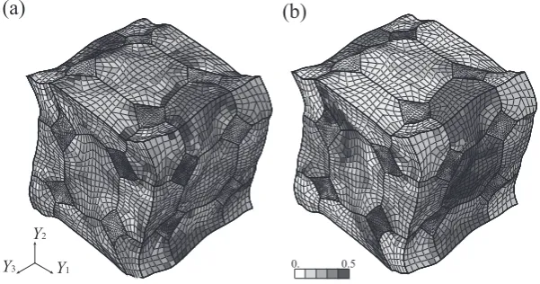
were discretized into 4320 elements (80 elements per grain) and 37,807 elements (2160 elements per grain), respectively. The crystallographic orientations of each grain were provided in a random fashion. The objective material was assumed to be pure copper composed of face-centered cubic (FCC) crys-tals. The initial pole figures of {111} are also shown in Fig. 2, which contains the number of points of crystal grains and the slip planes. The FE model (b ), which had the same structure as model (b) and was discretized into 1280 elements (80 ele-ments per grain), was prepared for comparison.
For the elastic constitutive model, the elastic constants at room temperature were taken from a database25) as follows:
ˆ
Ce1111=170,000.MPa, Cˆe1122=120,000.MPa,
ˆ
Ce1212=75,000.MPa (11)
For the plasticity, the material constants of eq. (10) were de-termined on the basis of experimental data on wire-drawing26) as follows:
τ(0α) =30.MPa, δτ(α)=180.MPa, h(0α)=70.MPa (12)
Here, the interaction matrix Ωαβ between slip systems is de-fined as two parts: self-hardening (α = β) and latent hardening (α ≠ β). The range of the ratio of the self-hardening and latent hardening coefficients is known to be [1.0, 1.4] for FCC
crys-tals27). Then, the following values were assumed for Ω αβ :
Ωαα =1.0, Ωαβ=1.1 (ifα β) (13)
Note that the above material constants were determined to reproduce the experimental stress–strain curve of the objec-tive materials phenomenologically because the constituobjec-tive model and material constants do not consider the macroscop-ic response of a polycrystalline aggregate and all mmacroscop-icro- and nanoscopic mechanisms.
Figure 3 shows the stress–strain responses of the single crystal when uniaxial tensile stresses are applied in three dif-ferent directions. The equivalent strain is defined as
ε∗:= 2 3dev
1 2ln FF
T : dev 1
2ln FF
T . (14)
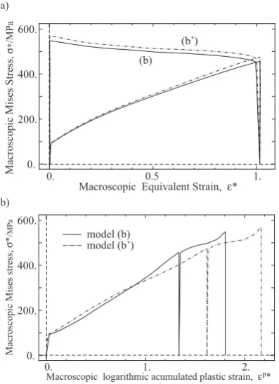
Based on the above constitutive model and material con-stants, FE analyses were carried out on models (a) and (b ) to evaluate the macroscopic initial anisotropy. Macroscopic uni-axial tensile stresses were applied in the three orthogonal di-rections. Figure 4(a) shows the macroscopic equivalent stress–strain curves. Although the same material constants were employed in both simulations, the macroscopic harden-ing behaviors were different. In general, these macroscopic responses converged with an isotropic response as more crys-tal grains were considered.
FE analyses of macroscopic uniaxial tensile stress for
Y1-direction were also carried out on Models (b) and (b ), which had the same morphology, to investigate the effect of the discretization. As shown in Fig. 4(b), the fine-mesh model (b) provided a slightly softer response than the coarse mesh model (b ), which is a well-known feature of a standard FE Fig. 1 Finite element models of the periodic polycrystalline aggregate. (a) 54 grains, 4320 elements, (b) 16 grains, 34,560 elements.
Fig. 2 Initial pole figures of {111} of finite element models (Fig. 1). (a) 54 grains, (b) 16 grains.
[image:3.595.146.443.71.200.2] [image:3.595.69.274.234.448.2] [image:3.595.324.526.240.365.2]formulation28). The results converged with a true solution to the mathematical problem when the finer mesh was used for the discretization.
The number of elements, FE formulation, degrees of free-dom, and performance of the interpolation function are essen-tial to describing the mechanical behavior. In our previous studies29,30), FE model (a) was confirmed to basically be suf-ficient to evaluate the macroscopic averaged response. How-ever, the macroscopic response was only one of the analysis objectives. Depending on the objective, convergence should be confirmed from not only the macroscopic viewpoint but also the microscopic viewpoint, such as regarding the defor-mation state and stress distribution of the microstructure. Considering the computational cost, it is not easy to develop a fully converged FE model in practice. In the current state, the discretization of FE model (b) was our best effort in the following simulations.
3. Finite Element Simulations of Polycrystalline Aggre-gate Subjected to Severe Plastic Deformation
SPD corresponding to multi-pass ECAE was imposed on the FE model of a periodic polycrystalline aggregate (Fig. 1(a)) to examine the evolution processes of the micro-structure.
3.1 Numerical simulations
The macroscopic displacement gradient corresponding to an orthogonal ECAE was repeatedly imposed on the FE mod-el for the simulations. The deformation state of an orthogonal ECAE can be described as a simple shear deformation. Then, the macroscopic displacement gradient can be described as
¯H=
0 0 0 0 0 0
γ 0 0
, (15)
where γ is the imposed simple shear strain. Based on the re-sults of the FE simulation of the corresponding ECAE sys-tem, γ was estimated to be 2.1, which is about 1.05 of the equivalent strain. A single pass of the ECAE is defined as the macroscopic displacement gradient (15) being imposed on the periodic polycrystalline aggregate shown in Fig. 1(a) and the macroscopic stress being released during the unloading process. Based on the single-pass simulation, the multi-pass simulation involves rotating and repeatedly imposing the macroscopic displacement gradient of (15). The billet was ro-tated 90◦ and 180◦ around the extruding direction (i.e., Y
3 -di-rection) during each pass on routes B and C, respectively.
3.2 Results and discussion
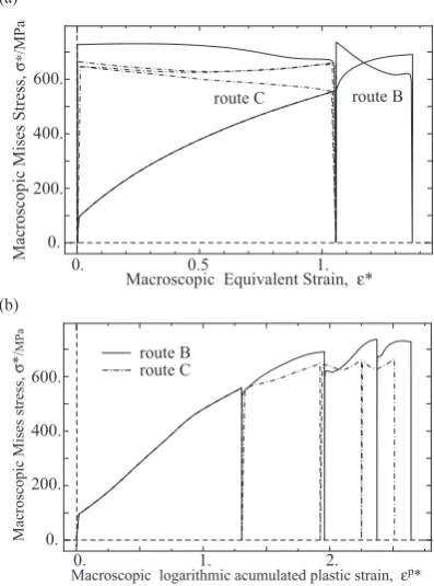
Figure 5(a) shows the resulting macroscopic equivalent stress–strain curves. The macroscopic equivalent strain be-came almost zero after four passes on route B and two and four passes on route C. To evaluate the amount of imposed strain, the macroscopic accumulated plastic strain was de-fined as the volume average of the logarithmic accumulated plastic strain:
εp∗:= 1 ΩY ΩY
ln[1+ξ]dΩY, (16)
where the accumulated plastic strain ξ is defined as
ξ:=
nslip
α=1
ξ(α), (17)
Fig. 4 Macroscopic equivalent stress–strain curves of polycrystalline ag-gregates for the macroscopic uniaxial tensile stress. (a) Effect of number of grains, (b) Effect of discretization.
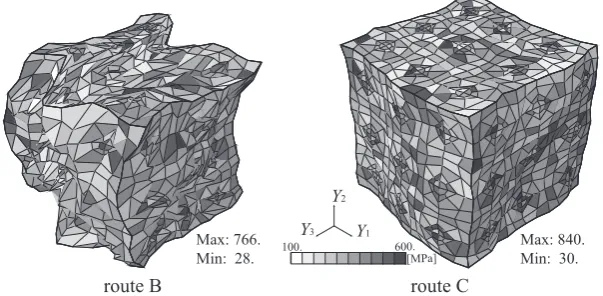
[image:4.595.71.272.72.348.2] [image:4.595.326.525.75.343.2]that is, the accumulated plastic strain ξ represents the amount of the inelastic strain at the crystal scale. Based on the above defined variable, the macroscopic responses in Fig. 5(a) were redrawn as shown in Fig. 5(b) to reflect the relationship be-tween the macroscopic equivalent stress and macroscopic ac-cumulated plastic strain, which reached over 250% of the logarithmic strain. Figure 5(b) indicates that route B was more effective at imposing the plastic strain than route C. Fig-ure 6 and Fig. 7 depict the deformation states and distribu-tions of the equivalent stress and accumulated plastic strain of the microstructures after four-pass ECAE. Even though the macroscopic stress was almost zero in both cases, a relatively high stress remained in the microstructure. The deformation states were completely different between routes B and C. In the case of route B, the microstructure was deformed in a complicated manner, and the accumulated plastic strain was distributed homogeneously by the imposition of different macroscopic strain modes at each pass. In the case of route C, in the other hand, the shape of the microstructure was pre-served even after four-pass ECAE, and the accumulated plas-tic strain was distributed locally because of the monotonic macroscopic strain modes. Note that further deformation analysis of multi-pass ECAE would possibly lose computa-tional accuracy, especially for route B, because the deformed FE model of route B contains distorted elements, as shown in Fig. 6 and Fig. 7.
Figure 8 graphs the evolution of crystallographic orienta-tions as a density plot. This was used to analyze the
heteroge-neous deformation states, where the horizontal axis is the extrusion direction. In experimental work18), the texture of the simple shear strain was observed after every pass of ECAE. Figure 8 clearly shows that the crystallographic tex-ture of the simple shear strain appeared with the first and sec-ond passes on route B and first and third passes on route C. However the texture was weak on the other passes, which in-volved a reversed strain. Li et al.18) reported the same tenden-cy with the standard self-consistent model; the grain co-rota-tion behavior contributed to obtaining the texture during the ECAE pass with the reversed strain. This implies that the heterogeneous deformation of the polycrystalline aggregate was inadequately represented–that is, the discretization of the Fig. 6 Deformation state and equivalent stress distribution of microstructure after four-pass ECAE.
Fig. 7 Deformation state and accumulated plastic strain distribution of microstructure after four-pass ECAE.
[image:5.595.147.449.76.224.2] [image:5.595.149.447.270.416.2] [image:5.595.313.541.453.592.2]4.1 Numerical simulations
Similar to the work presented in the previous section, the macroscopic deformation corresponding to two-pass ECAE on route C was imposed on a FE model, as shown in Fig. 1(b). For comparison, the same calculation was carried out with the coarse-mesh model (b ).
caused by the discretization of the microstructure.
[image:6.595.70.269.295.569.2]Figure 11 shows the states of the crystallographic orienta-tion {111}. Figure 12 indicates the intensity of pole figure Fig. 11 along the horizontal line, which is normalized with the average values of overall pole figures. The fine mesh mod-el provided the smoother distribution of the density in these pole figures. That is, the coarse mesh model has still a short-age of the ability to express the heterogeneous deformation state. In this context, the crystallographic texture of simple shear was observed in the case of the fine mesh, even after the second pass of route C. Figure 13 shows the distributions of the nominal vector component of the {111} slip plane as the corresponding data from the microscopic perspective. These
[image:6.595.316.540.374.448.2]Fig. 10 Deformation state and accumulated plastic strain distribution of the microstructure after two-pass ECAE on route B. Fig. 11 Evolution of pole figure of {111} with multi-pass ECAE.
Fig. 12 Comparison of intensity of pole figure along horizontal line of Fig. 11.
[image:6.595.312.541.478.559.2] [image:6.595.152.447.613.771.2]values were continuously distributed through the original grain boundary, which represents the interaction effect be-tween the crystal grain and grain co-rotation behavior. These results are consistent with those of the previous study18), which addressed the importance of the grain co-rotation. Thus, we conclude that fine discretization is conceptually re-quired to represent the heterogeneous deformation at the mi-cro-scale. However, such computations are expensive. For reference, the simulation of the fine-mesh model consumed a CPU time of about 2.0 × 10⁶ s.
5. Conclusions
We carried out FE analyses to reproduce the heterogeneous deformation after multi-pass ECAE where a large amount of macroscopic logarithmic accumulated plastic strain was im-posed on a polycrystalline aggregate. The numerical results were analyzed from multi-scale viewpoints, where the under-lying mechanism of the macroscopic response was explained on the basis of the evolution of the crystallographic texture and the deformation state of the microstructure. Based on the results, computational discretization methods have the poten-tial to deal with the deformation process by explicitly consid-ering the interaction effect between crystal grains. However, massive computational efforts are required to carry out prac-tical simulations using an FE mesh that is sufficiently fine to reproduce the heterogeneity of the deformed microstructure.
This study demonstrated the difficulty with setting up FE models of a microstructure. Obviously, it would be more dif-ficult to validate the numerical simulations by using advanced constitutive models11,12). A method to validate simulations and models should be established in this field. The simulation in this study can be used as a benchmark for FE mesh valida-tion.
Acknowledgement
This research was supported by Grants-in-Aid for Scientif-ic Research on Innovative Areas Bulk Nanostructured Met-als (No. 23102513 and No. 25102711) and Young Scientists (No. 15K18205).
REFERENCES
1) V.M. Segal: Mater. Sci. Eng. A 271 (1999) 322–333.
2) M. Furukawa, Z. Horita, M. Nemoto and T.G. Langdon: J. Mater. Sci. 36 (2001) 2835–2843.
3) A. Zhilyaev and T. Langdon: Prog. Mater. Sci. 53 (2008) 893–979. 4) Y. Saito, H. Utsunomiya, N. Tsuji and T. Sakai: Acta Mater. 47 (1999)
579–583.
5) N. Tsuji, Y. Saito, S.-H. Lee and Y. Minamino: Adv. Eng. Mater. 5 (2003) 338–344.
6) H.S. Kim: Mater. Sci. Eng. A 328 (2002) 317–323.
7) S.C. Yoon, Z. Horita and H.S. Kim: J. Mater. Process. Technol. 201 (2008) 32–36.
8) T. Inoue, A. Yanagida and J. Yanagimoto: Mater. Lett. 106 (2013) 37– 40.
9) M. Gotoh: Int. J. Numer. Methods Eng. 12 (1978) 101–114.
10) F. Roters, P. Eisenlohr, L. Hantcherli, D.D. Tjahjanto, T.R. Bieler and D. Raabe: Acta Mater. 58 (2010) 1152–1211.
11) T. Ohashi, M. Kawamukai and H. Zbib: Int. J. Plast. 23 (2007) 897– 914.
12) I. Watanabe, D. Setoyama, N. Iwata and K. Nakanishi: Int. J. Plast. 26 (2010) 570–585.
13) G.I. Taylor: J. Inst. Met. 62 (1938) 307–324.
14) J.F.W. Bishop and R. Hill: Philos. Mag. 42 (1951) 414–427. 15) R. Hill: J. Mech. Phys. Solids 13 (1965) 89–101.
16) R.A. Lebensohn and C.N. Tome: Acta Metall. Mater. 41 (1993) 2611– 2624.
17) I.J. Beyerlein and L.S. Toth: Mater. Sci. Eng. A 345 (2003) 122–138. 18) S. Li, I.J. Beyerlein, D.J. Alexander and S.C. Vogel: Acta Mater. 53
(2005) 2111–2125.
19) I.J. Beyerlein and L.S. Toth: Prog. Mater. Sci. 54 (2009) 427–510. 20) C.N. Tome, C.T. Necker and R.A. Lebensohn: Metallurgical and
Mate-rials Transactions A33 (2002) 2635–2648.
21) R. Becker: Acta Metall. Mater. 39 (1991) 1211–1230.
22) I. Watanabe and K. Terada: Int. J. Mech. Sci. 52 (2010) 343–355. 23) C. Miehe, J. Schroder and J. Schotte: Comput. Methods Appl. Mech.
Eng. 171 (1999) 387–418.
24) K. Terada and I. Watanabe: Comput. Mech. 40 (2007) 497–511. 25) G. Simmons, W. Herbert, Single Crystal Elastic Constants and
Calcu-lated Aggregate Properties. MIT Press, Cambridge, 1971.
26) J.G. Sevillano, P. Van Houtte and E. Aernoudt: Prog. Mater. Sci. 25 (1980) 69–412.
27) U.F. Kocks: Metallurgical and Materials Transactions 1 (1970) 1121– 1143.
28) E.A. de Souza Neto, D. Peric, D.R.J. Owen, Computational Methods for Plasticity: Theory and Applications. John Wiley & Sons Ltd., Hoboken, NJ, 2008.
29) K. Terada, I. Watanabe and M. Akiyama: Int. J. Multiscale Computa-tional Engineering 4 (2006) 445–460.
[image:7.595.146.447.71.229.2]30) I. Watanabe, K. Terada, E.A. de Souza Neto and D. Peric: J. Mech. Phys. Solids 56 (2008) 1105–1125.