crack propagation does not increase even by strain reduction and temperature increase, since cavity formation is suppressed by viscous defor-mations of grain interior. Fatigue crack propagation rate is controlled only by strain energy which is the driving force for crack propagation. As a result, the rate of crack propagation and the number of crack initiation cycles can be assessed by ΔJ, not by strain rate and temperature.
[doi:10.2320/matertrans.MD201504]
(Received December 2, 2015; Accepted February 4, 2016; Published April 8, 2016)
Keywords: Lead-free solder, Bi-Sn eutectic alloy, Fatigue crack propagation, Strain rate, deformation mechanism, Temperature dependence, J-integral
1. Introduction
Following the regulatory restriction in place on the use of lead-containing solders, Sn-Ag-Cu alloys have now been caught on as the mainstream in surface mount soldering of electronics devices. however, Sn-Ag-Cu solders have higher melting points than the conventional Sn-Pb solder, posing a problem that necessitates an increase in soldering tempera-ture accordingly. In association with the continued and last-ing micronization and high densification of electronics devic-es, the realization of low temperature surface mounting process with low thermal load is essential and the develop-ment of lead-free solders with low melting points is required. In the situation, a Bi-Sn eutectic alloy is drawing attention as one of the alloys that can satisfy the above requirements. The melting temperature of Bi-Sn eutectic alloy is as low as 139 C so that low temperature soldering with Bi-Sn solder allows for reduction in thermal load to the peripheries of mounted components1). And, even for reducing environmental load during the mount processing, practical soldering with the im-plementation of Bi-Sn eutectic solder is desired2). Mechani-cal characteristics of a Bi-Sn eutectic alloy are represented by strain rate sensitivity. In high strain rate range, the alloy ex-hibits a brittle behavior while it exex-hibits a superplastic phe-nomenon in which an elongation at failure becomes 1000% when tensioned at low strain rates3). For the practical use, comprehension of the alloy s strain-rate dependence that af-fects fatigue reliability is necessary. Resent study clearly shows that the low cycle fatigue crack initiation life of a Bi-Sn eutectic alloy is greatly affected by temperature and strain rate4,5). However, in the problematic fatigue life of electronics devices mounted, the number of cycles is mostly spent for crack propagation. So, elucidating crack growth behavior of a Bi-Sn eutectic alloy becomes important. The detail is not known because of experimental difficulty. So, with a focus on micro fatigue cracks of Bi-Sn eutectic alloy, effects of strain rate and temperature on fatigue crack growth were
investigat-ed in this study.
2. Experimental
2.1 Specimen
Bi-42mass%Sn solder paste (Senju Metal Industry: L20-BLT5-T8F) was used in this study. Single edged notched (SEN) specimen shown in Fig. 1 was employed for fatigue crack propagation test. The specimen was fabricated by fol-lowing method. The solder paste was spread in the groove made on a brass flat bar, and the solder was molten and solid-ified in the groove. Then, the specimen was shaped by cutting out by machining from the brass flat bar. The soldering was done at +50 K above the melting temperature in nitrogen at-mosphere. The notch was processed by a precision wire saw. Lastly, the specimen was mirror-finished by machine polish-ing. Figure 2 shows the secondary electron image of the spec-imen. White contrast area is Bi phase and black contrast area is Sn phase in Fig. 2. The average distance between phases was about 2.8 μm.
2.2 Fatigue crack propagation test
Fatigue crack propagation test was performed by a dis-placement controlled pulsating tensile-tensile low cycle fa-tigue test. The controlled wave form was a symmetric triangle wave; test temperatures were two levels of 298 K and 371 K; the total strain range was 0.75%; and strain rates were three levels of 1 × 10⁻²/sec, 1 × 10⁻³/sec and 1 × 10⁻⁴/sec. For a
*
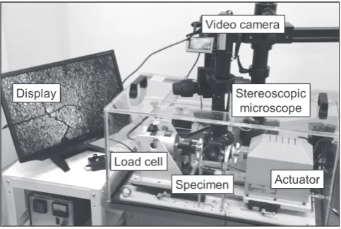
[image:1.595.305.548.688.770.2]certain specimen, the strain range levels of 0.5% and 1% were added to obtain more comprehensive results. For a fatigue test machine, a micro load fatigue test machine with the adoption of a piezo actuator shown in Fig. 3 (Saginomiya Seisakusho: LMH207-20) was used. For displacement measurements, a capacitance type displacement sensor mounted on a jig near the specimen was used; and the values measured by the sen-sor were used for controlling the actuator. Test temperature was controlled by a ceramic heater installed inside the speci-men fixing jig and the operating temperatures were main-tained with the deviations of ±2 K during the test by a ther-mocouple fixed on the specimen fixing jig. For crack length measurements, motion video was recorded through the test by a stereomicroscope (Leica: Z16 APO) installed on the up-per part of the fatigue test machine. Crack lengths were mea-sured in the range where the effects of bending deformation concomitant with ligament width reduction in the specimen by crack growth does not become prominent, because the SEN specimen was used in this study. The fatigue crack prop-agation rate was computed by a quadratic polynomial approx-imation. A fatigue crack propagation testing machine was shown in Fig. 3.
2.3 Assessment of fatigue crack propagation rate by fracture mechanics parameters
In this study, cyclic J-integral, ΔJ, commonly adopted as a parameter of elasto-plastic fracture mechanics was used. J in-tegration is the propagation force expressed with the field of stress or displacement apart from a crack tip. ΔJ is defined by the Eq. (1).
∆J=
Γ
ψ(∆εi j)dy−∆Ti∂∆ui
∂x ds (1) Where, Γ is the integration path advancing in the anticlock-wise direction around a crack tip, ΔTi is the path surface vec-tor, Δui is the displacement vector along Γ, ds is the incremen-tal length along Γ, and ψ is the quantity relating to the strain energy density. There is no simplified equation for ΔJ for the SEN specimen, so ΔJ was obtained by Finite Element Analy-sis (FEA). The analyAnaly-sis model was 1/2 symmetric with the employment of an eight-node quadrilateral plane strain ele-ment created for each crack length (shown in Fig. 4). In the region of 20 × 20 μm around crack tips in the analysis model, the element was divided into squares with each side 2 μm. The ANSYS ver.15.0 solver was used. On the assumption that the shape of cyclic stress-strain curve is similar to the process of tensile loading of the hysteresis loop, ΔJ was computed by the method of quadrupling the J-integration obtained from the analysis of the 1/4 cycle tensile loading process6) based on the cyclic stress-strain curve proposed by Asada, et al – that is, Eq. (2) was used6).
∆J=4JFEM (2)
where, JFEM is the J integral of tensile loading process ob-tained from FEA. FEA was elasto-plastic analysis and for the constitutive equation, the yield function shown in Eq. (3) and the non-linear hardening rule (Chaboche model) shown in Eq. (4) were used.
f =(σ, εp)=σ¯ −A3 (3)
˙ χ=2
3 2
i=1
A1ε˙p−A2χi˙p (4)
where, χ is the back stress rate, ˙ ε is the inelastic strain rate, χ ˙ is the back stress, ˙p is the accumulated inelastic strain rate, and A2 and A3 are the constants. Material properties used for
Fig. 2 Secondary electron image showing as-solidified microstructure.
Fig. 3 Appearance of fatigue crack propagation testing machine.
[image:2.595.49.290.67.251.2] [image:2.595.305.549.69.226.2] [image:2.595.48.290.297.459.2]curve in Fig. 6 tends to decline with decreasing strain rate and increasing temperature, when compared with in the same strain range. And the number of cycles at crack initiation from the notch increases with strain rate reduction and tem-perature increase. In common structural materials and solder alloys, it is generally known that with decreasing strain rate and increasing temperature, fatigue crack initiation life tends to become short and fatigue crack propagation rate tends to increase7–11). The trend of strain rate and temperature depen-dence of Bi-Sn eutectic alloy was quite opposite to that gen-erally observed in structural materials and other solder alloys which is an interesting finding. However, at 371 K, 1 × 10⁻⁴/s, 0.75%, despite a decrease in strain rate, the fatigue crack initiation life was short and the rate of micro fatigue crack growth was accelerated. This was caused by micro-structure coarsening by strain-inducing grain growth.
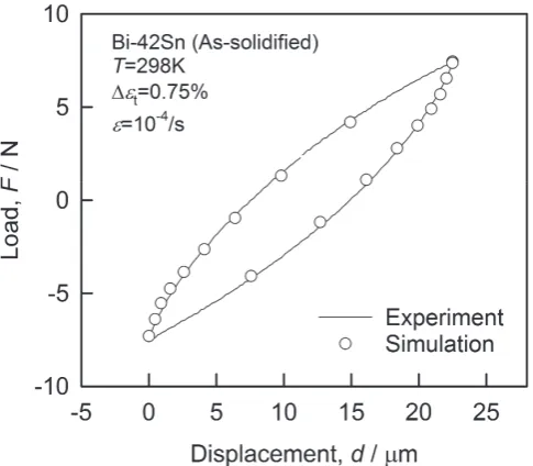
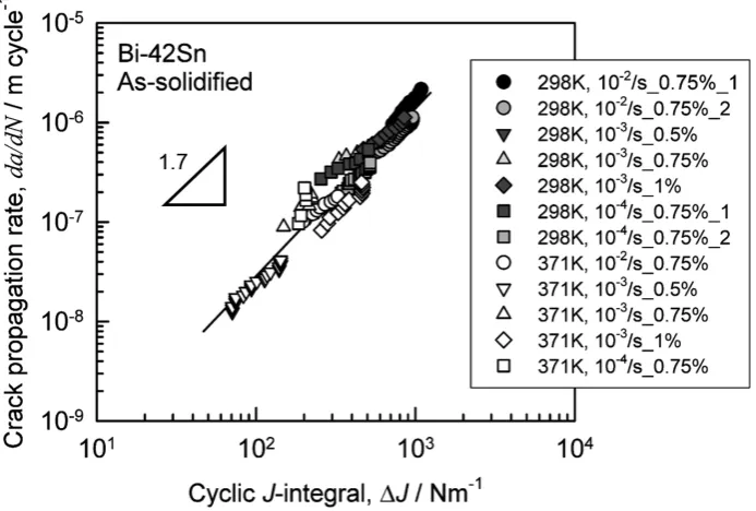
Figure 7 shows the relationship between fatigue crack propagation rate and ΔJ of Bi-Sn eutectic alloy. The rate of fatigue crack propagation tends to increase with an increase in the ΔJ, while the relationship between ΔJ and fatigue crack Fig. 5 Load-displacement hysteresis loops obtained from experiment and
FEA.
[image:3.595.117.476.484.771.2]propagation rate is of linear with a straight line under any experimental condition in Fig. 7. The crack propagation rate obeys Dowling-Begley law shown in Eq. (5).
da
dN =C1∆JC2 (5)
where C1 and C2 are the material constants. C1 and C2 were determined to be 8 × 10⁻¹² and 1.7 respectively.
This result has clarified that it is possible to assess the fa-tigue crack propagation rate in a Bi-Sn eutectic alloy by ΔJ, not by strain rate and temperature, which indicates that the fatigue crack propagation rate of a Bi-Sn eutectic alloy is not dependent on temperature and strain rate, and is dependent
only on strain energy, suggesting the number of fatigue crack initiation cycles is also dependent on strain energy.
Figure 8 shows the relationship between the number of cy-cles at fatigue crack initiation and inelastic strain energy den-sity ΔW, where N0 is the number of cycles when the crack length is zero, which was obtained by extrapolating the crack propagation curve shown in Fig. 6 into the zero crack length. ΔW was computed by FEA, and average value in the region of 10 × 20 μm in front of the notch. N0 has a power law relation-ship shown in Eq. (6) with ΔW.
N0=C3∆WC4 (6)
where, C3 and C4 are the material constants. As shown in
Fig. 7 Relationship between crack propagation rate and ΔJ at 298 K under each condition.
[image:4.595.126.473.72.306.2] [image:4.595.122.474.354.588.2]Fig. 8, the relationship between N0 and ΔW mostly takes the form of a straight line under any experimental condition. In this study, C3 and C4 were found to be 427.7 and −0.73 re-spectively. Thus, it was clarified that fatigue crack initiation life as well as fatigue crack propagation rate was dominated by ΔW, not by strain rate and temperature.
4. Discussion
In high temperature fatigue in metal materials, generally crack initiation life decreases with decreasing strain rate and increasing temperature8,9). However, in a Bi-Sn eutectic alloy, when compared with in the same strain range, fatigue crack initiation life becomes long with decreasing strain rate and increasing temperature and fatigue crack propagation rate is lowered. Moreover, fatigue crack initiation life and fatigue crack propagation rate are dominated only by inelastic strain energy density. In other words, decreased strain rates and in-creased temperatures are not harmful to the rate of high tem-perature crack growth in a Bi-Sn eutectic alloy. The strain-stress curve obtained from the static tensile testing is shown in Fig. 9. It is clear from the illustration that decreasing strain rate and increasing temperature substantially decrease the flow stress. Generally, creep deformation mechanism is dis-cussed using following equation.
˙
ε=A3σnexp(−Q/RT) (7)
where ε is the strain rate, n is the stress exponent, Q is the ˙ activation energy, R is the gas constant, T is temperature and A3 is material constant. The stress exponent depends on the deformation mechanism. Eq. (7) is rewritten as:
˙
εexp(Q/RT)=A3σn (8)
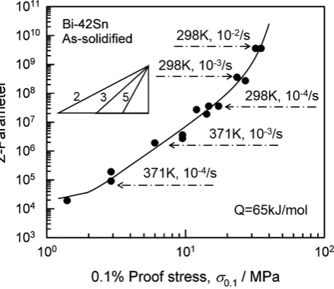
The left side of Eq. (8) is often called the temperature-com-pensated strain rate or the Zener-Hollomon parameter, Z12). Z is given as:
Z=ε˙·exp(Q/RT) (9) In order to compare the data measured at different
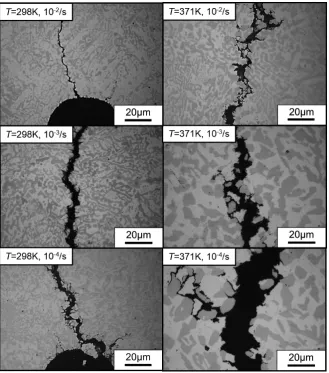
[image:5.595.49.297.68.281.2] [image:5.595.310.547.71.276.2]tectic alloy, Sn forms a Bi-dissolved solid solution. This Sn solid solution, called as a Class I solid solution has been re-ported that huge elongation is observed in the low Z region, without requiring the grain boundary sliding, by the solute atmosphere dragging mechanism16,17). And as for Bi, which is not a Class I solid solution, it has been reported that at high temperature the number of active sliding systems increases and the deformation capability of grain interior is enhanced18). In fatigue deformation in the low Z region in Bi-Sn eutectic alloy, the deformations of Sn solid solution and Bi behave as the concomitant mechanisms of grain boundary sliding. And cavity formation and growth at grain boundary triple points do not seem to be marked. As the Z lowers, the strain energy that drives fatigue crack propagation decreases. Because of this, it is considered that if cavity formation and growth are not prominent, fatigue crack propagation rate decreases with a decrease in strain rate and an increase in temperature. Thus, when compared with in the same strain range, fatigue crack initiation life increases with a decrease in strain rate and an increase in temperature. However, like the condition of 371 K, 1 × 10⁻⁴/s, 0.75%, if microstructure become coars-ened, the concomitant mechanisms are thought to have fewer effects on suppressing cavities, increasing fatigue crack prop-agation rate by grain boundary sliding.
5. Conclusions
(1) The micro fatigue crack propagation rate in a Bi-Sn eu-tectic alloy, when compared with in the same strain range, decreases with a decrease in strain rate and an increase in temperature. This is an opposite trend to the effect of strain rate and temperature observed in common high temperature fatigue fractures.
(2) The deformation mechanism of a Bi-Sn eutectic alloy becomes grain boundary sliding in the low Z region. Howev-er, due to cavity formation being suppressed by viscous de-formations of grain interior, fatigue crack propagation does not increase even by strain reduction and temperature in-crease.
(3) Fatigue crack propagation rate is controlled only by strain energy which is the driving force for crack propagation. As a result, the rate of crack propagation and the number of crack initiation cycles can be assessed by ΔJ, not by strain rate and temperature.
Acknowledgments
[image:6.595.134.464.69.443.2]We are grateful to Mr. Yoshitaka Toyoda, Senjyu Metal In-dustry Co. LTD., for providing solder paste.