Effects of Forming Conditions of Roll Offset Method on Sectional Shape
at the Corner of Square Steel Pipe
+Takuo Nagamachi
1, Takefumi Nakako
2and Daisuke Nakamura
21Institute of Technology and Science, University of Tokushima, Tokushima 770-8506, Japan 2Steel & Technology Development Laboratories, Nisshin Steel Co., Ltd., Sakai 592-8332, Japan
Square steel pipes are reshaped from welded round pipes by roll-forming. Effects of the roll diameter on the cross-sectional size of the square steel pipe were investigated by experimentation and three-dimensionalfinite element simulation. When the top roll diameter is greater than that of the side roll, then the width of a corner part of the formed pipe is greater than the height. The square steel pipe was formed by offsetting the small roll to the upstream side to make the width and height of a corner part equal. The offsetting result is affected by the longitudinal contact distance between a roll and a pipe. The geometric contact length and relative offset, the offsetting distance/geometric contact length, were defined. The optimum value of the relative offset was clarified, which increased with the expansion of the contact length of a top roll, the roll gap and the round pipe wall thickness. [doi:10.2320/matertrans.P-M2013815]
(Received August 31, 2012; Accepted June 8, 2013; Published August 2, 2013)
Keywords: roll forming, square steel pipe, roll diameter, offset,finite element (FE) simulation
1. Introduction
Square steel pipes, normally produced by roll forming, are used widely as structural elements of buildings and machines. In the forming process, a roll set consisting of a top and bottom pair and a side pair, is generally arranged. Then several roll sets are connected tandemly. A circular pipe is pushed into the virtually square-shaped calibers of the center of the roll set. Bent corners and re-bent sides are formed in the cross section of the circular pipe. Finally the circular pipe is changed into a square pipe. On this subject, Kiuchiet al.1)
have conducted a series of experimental studies. To date Onoda et al.2)reported an experimental investigation based
on their numerical analyses.
When designing a roll-forming machine for production of square steel pipes, the diameter of the paired top and bottom rolls is usually set as larger than that of the side roll pair. Thereby interference is avoided between the roll axes driven by electric motors. The authors have conducted experiments and FE simulations for top and bottom rolls with diameters larger than those of side rolls.3)Results show the following:
(1) the width of the formed pipe becomes smaller than its height, (2) it is therefore necessary to performfinish forming with a small increment of reduction to obtain a real square pipe, (3) the width of the corner is larger than its height, (4) offset forming in which roll pairs with smaller diameter are offset in the upstream direction is effective to produce pipes with equal width and height of the corner part.
In this study, extended forming experiments and FE simulations are conducted to verify the results of offset forming in our previous report. We were able to ascertain the offset conditions to provide a sound corner shape are verified by examining the effect of the diameter ratio of top-bottom rolls to those of side one, reduction from circular pipe to square one and the initial thickness of the circular pipe, on relationship between amount of the offset and the geometry at the corner.
2. Experiment and Analysis
Figure 1 presents a schematic view of the forming process used in this study. Hydraulic cylinder pushes the circular pipe into square-shaped roll calibers consisting of four roll sets. After passing roll sets, the square steel pipe is discharged
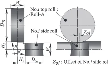
finally. No rolls are driven in this process. Roll names and their dimensions are presented in Fig. 2 and Table 1. Rolls from A to D listed in the table have different diameters respectively. Three combinations of top and bottom rolls and side rolls, A-B, A-C and A-D, were investigated in a previous
Fig. 1 Schematic illustration of forming processes.
Fig. 2 Notations of roll dimensions. +This Paper was Originally Published in Japanese in J. JSTP 52(2011)
10781082.
[image:1.595.313.540.466.616.2] [image:1.595.331.521.656.771.2]study.3) Two combinations of B-C and C-D are added for
further examination of the effect of diameter ratioDTi/DSion
the cross-sectional size at the corner.
Here, geometric contact lengths are shown in Fig. 3 as a parameter representing diameter and configuration of rolls. These values ati-th process,LTiandLSi, might be calculated
using the following equations for top and bottom rolls and side rolls, respectively.
LTi¼
ffiffiffiffiffiffiffiffiffiffiffiffiffiffiffiffiffiffiffiffiffiffiffiffiffiffiffiffiffiffiffiffiffiffiffiffiffiffiffiffiffiffiffiffiffiffiffiffiffiffiffiffiffiffiffiffiffiffiffiffiffiffiffiffiffi
DTi
2
2
D2TiHi1þHi
2
s
ð1Þ
LSi ¼
ffiffiffiffiffiffiffiffiffiffiffiffiffiffiffiffiffiffiffiffiffiffiffiffiffiffiffiffiffiffiffiffiffiffiffiffiffiffiffiffiffiffiffiffiffiffiffiffiffiffiffiffiffiffiffiffiffiffiffiffiffiffiffiffi
DSi
2
2
DS2iHi1þHi
2
s
ð2Þ
Nomenclature is presented in Fig. 2 and Table 1. For No. 1 process (i=1), Hi¹1=H0=d0/2 (radius of the circular
pipe).
Table 2 presents mechanical properties obtained from tensile tests with a test piece. This is cut from a circular tube with the initial thickness t0 of 2.11 mm, which is
equivalent to a STK400 galvanized steel tube.
The experimental apparatus places limits on experimental conditions. 2.11 mm on initial thickness t0, 21.4% on
reduction ri and 7.5 mm on offset Zoi. For conditions of t0 heavier than 2.11 mm, r3 larger than 23.3% and roll
combinations except A-B, FE simulation is employed. This is conducted separately at each stand using a static implicit scheme applied to transient elasto-plastic analysis. Other
details of the analysis are the same as those described in the previous report.3) The domain for FE simulation is divided into hexahedral elements with eight nodes. Three elements are allocated in the thickness direction. The total number of elements is approximately 15,000 to 20,000 and 0.12 was assumed for the coefficient of Coulomb friction. Mechanical property of a circular pipe with initial thickness
t0 between 1.06 and 4.23 mm is assumed to be the same
as that shown in Table 2. A general-purpose code of DEFORM-3D Ver. 6.1 was used for calculation. It took for 12 to 24 h in one forming stand on a PC with a Core 2, 3.0 GHz processor.
3. Results and Discussions
3.1 Influence of diameter ratio of top and bottom rolls to side rolls
[image:2.595.45.291.73.429.2]Althoughfinal dimensions of the cross-section that passed through three stands are important, the pipe that passed only the No. 1 stand and No. 1 and No. 2 stands were evaluated to make clear the effects of upstream deformations on cross-sectional dimensions of thefinal product. The nomenclature for cross-sectional dimensions of the formed pipe is shown in Fig. 4. The peripheral part that made contact with the roll is defined as the side, and that which made no contact with it as the corner, while the boundary between these two parts as the shoulder. The width and the height of the corner (between two shoulders) are designated assxand syrespectively; sais
the average of these two.
Figure 5(a) demonstrates the average sa versus diameter
ratio of top and bottom rolls to that of side rollsDTi/DSiand
Fig. 5(b) deviation of sy from sa, (sy¹sa)/sa. Ratio of the
thickness to the outer diameter t0/d0 is 3.9% and reduction
r3 is 19.6%. sa for every stand keeps almost constant for
increasing DTi/DSi. Whereas, (sy¹sa)/sa decreases with
increasing DTi/DSi and becomes negative, namely sx>sy
forDTi/DSi>1.0. This status is expressed as“corner droop”.
This occurrence can be explained by contact conditions between the pipe and the roll,3) as follows. Because of the
difference in roll diameters between the top and bottom pair and the side pair, lengths of longitudinal contact differ
Table 1 Path schedules.
(a) Roll gap
Square pipe A/mm
No. 1 process No. 2 process No. 3 process
H1/mm r1/% H2/mm r2/% H3/mm r3/%
43.5 23.70 12.2 22.38 17.1 21.72 19.6
42.5 23.39 13.4 21.95 18.7 21.22 21.4
41.5 23.08 14.5 21.51 20.3 20.72 23.3
Reductionri=(d0¹2Hi)/d0
(b) Roll dimension
Process No.i
DTi,DSi/mm
R/mm W/mm Roll-A Roll-B Roll-C Roll-D
No. 1 161.5 104.5 81.0 54.0 97.50 40.70 No. 2 161.5 104.5 81.0 54.0 236.86 40.98 No. 3 162.1 106.9 81.0 54.0 ¹531.46 41.02
[image:2.595.303.551.84.157.2]Fig. 3 Definition of geometrical contact length (LTi,LSi).
Table 2 Mechanical properties of round pipe.
Wall thickness: 2.11 mm Young’s modules: 206.8 GPa Poisson’s ratio: 0.3 Yield stress: 387.9 MPa nvalue: 0.215
Flow stress:·¼468:4 ¾0:671þ387:9MPa
[image:2.595.52.285.239.397.2] [image:2.595.79.291.554.618.2]between two roll pairs. The longer contact length by the top and bottom rolls compared with that by side rolls causes the corner to shift from top to side. Then the shoulder of the top side goes away from the corner center and that of the side approaches it.
Kondo et al.4) described four-roll forming of wire and rods, whereby the longitudinal offset of axes of side roll pairs in the upstream direction (¹z direction) made the product wider horizontally. Considering the shift of the corner from top to side in our study as widening deformation by top and bottom rolls, suppression of the widening deformation and therefore the corner droop described above are expected by offsetting side rolls to the upstream direction. In our previous study,3)experiments and FE simulation for roll combinations
[image:3.595.48.289.327.478.2]of A-B, A-C and A-D were conducted. The effectiveness of side rolls offsetting was confirmed to form products that have a corner with the equal width to the height. In the current study adding some more combinations of rolls, additional FE simulations were conducted.
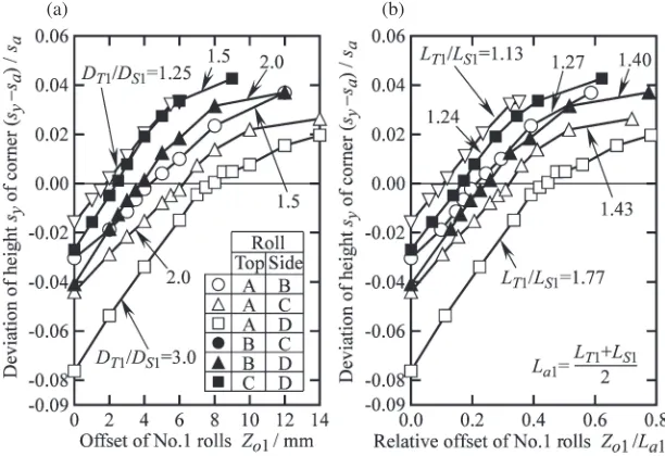
Figure 6 shows the corner deviation (sy¹sa)/sa versus
side roll offsetting Zoi for No. 1 stand. Side roll offsetting Zoishows the longitudinal distance between the center of top
and bottom rolls and that of side rolls, and is presented in Fig. 2. Figure 6(a) shows that (sy¹sa)/sa approaches zero
with increasingZoi. Therefore, the corner droop is balanced.
However, too much offsetting of Zo1 causes results with
(sy¹sa)/sa>0 and therefore sx<sy, which means an
inverse corner droop. To balance corner droop, (sy¹sa)/
sa=0, Zo1 of 6.2 mm is found for DT1/DS1=2.0, the roll
combination of A-C and marked by . For combinations B-D, marked by , Zo1 is 4.0 mm for the same value of
DT1/DS12.0. For a combination of smaller rolls such as B-D,
the longitudinal contact length for top and bottom rolls is short and widening deformation of pipe occurs in the adjacent region to the roll center. This fact might explain the smaller offsetting of side rolls to suppress widening deformation.
Relative offset Zo1/La1 is introduced to normalize the
offset, whereLa1is the average of geometrical contact length
between the pipe and the roll denoted byLT1andLS1, which
was defined respectively in eqs. (1) and (2). The relationship between (sy¹sa)/sa and Zo1/La1 is shown in Fig. 6(b).
LT1/LS1 is shown in the same figure as a parameter
representing the roll combination. This figure suggests that,
Zo1/La1 that makes (sy¹sa)/sazero becomes larger as LT1/
LS1is increased. One mightfind the optimum offset balancing
corner droop uniquely for any combination of rolls by making use of the geometrical contact length.
Figure 7 shows (sy¹sa)/sa of pipes after successive
offset forming by stands No. 1 and No. 2. Results for roll combinations of B-C, C-D and B-D are shown. Because the reduction increment at No. 3finishing process is quite small, pipe shape after No. 3 process marked by , shows little difference in that after No. 2 process, marked by , as shown in Figs. 5(a) and 5(b). This fact suggests that forming work should be made only by No. 1 and 2 stands to obtain products with small droop.
(a) (b)
Fig. 6 Effect of ratio of roll diameter on relationship between offset and deviation of corner shape of pipe formed by No. 1 rolls (t0/d0=3.9l%,r1=12.2%, simulation results); (a) (sy¹sa)/savs.Zo1(b) (sy¹sa)/savs.Zo1/La1.
(a) (b)
Fig. 5 Relationship between ratio of roll diameter and corner shape of pipe formed by No.i rolls (t0/d0=3.9%, r1=12.2%, r2=17.1%, r3=19.6%); (a) Average of height sy and width sx of corner, (b)
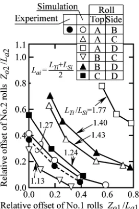
[image:3.595.144.450.552.762.2]Several combinations of offset at No. 1 and 2 stands eliminating corner droop are possible for roll diameter ratios of, top-bottom rolls and side rolls, as shown in Fig. 7. Figure 8 summarizes combinations obtained from 7 types of experiments and 127 types of FE simulations.
3.2 Effect of reduction
The effect of reduction from a circular pipe to a square one on sectional dimensions of formed pipes is discussed, for 3.9%with ratio of thickness to outer diameter of circular pipe
t0/d0, and 19.6, 21.4 and 23.3% withfinal reductionr3.
Figure 9 demonstrates effects of reduction r1 on
relation-ship between sa and DTi/DSi and that between (sy¹sa)/sa
and DTi/DSi for No. 1 process. In Fig. 9(a), sa is almost
constant with increasing DTi/DSi, but it decreases rapidly
with increasing r1 for the fixed DTi/DSi. In Fig. 9(b),
(sy¹sa)/sais decreased with increasing DTi/DSi, but this is
nearly kept constant with varying r1 for the fixed DTi/DSi.
These results are the same in the real product. With
increasing r1, (sy¹sa)/sa is nearly kept constant, but sa is
decreased rapidly. This means that actual difference between height and width of the corner sy¹sa (=sy/2¹sx/2) is
decreased rapidly with increasingr1. For small difference of
sy¹sa, a small offset might eliminate the corner droop.
The effect of reduction r1 on the relationship between
Zo1/La1 and (sy¹sa)/sa for No. 1 process is presented in
Fig. 10. Inferring from results presented in Fig. 9, Zo1/La1
that makes (sy¹sa)/sazero is decreased with increasingr1in
every combination of rolls.
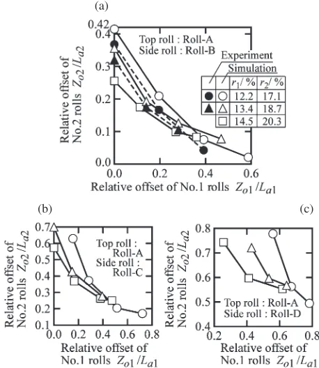
Figure 11 summarizes those combinations of offset at No. 1 and 2 stands eliminating corner droop. These have been found from 14 types of experiments and 139 types of FE simulations. As reduction becomes larger, corner droop can be eliminated with smaller Zo1and Zo2.
3.3 Effect of initial pipe thickness
The effect of the initial thickness on sectional dimensions of formed pipes is discussed, for 19.6%in reduction r3with
2.0, 3.9, 5.9 and 7.8% in ratio of the thickness to the outer diameter of circular pipe t0/d0.
Figure 12 demonstrates effects of t0/d0 on relationship
between sa and DTi/DSi and that between (sy¹sa)/sa and
(a) (b) (c)
Fig. 7 Effect of offsetZo1on relationship between offsetZo2and deviation of corner shape of pipe formed by No. 2 rolls (t0/d0=3.91%, r1=12.2%,r2=17.1%, simulation results); (a)LT2/LS2=1.14 (b)LT2/LS2=1.23 (c)LT2/LS2=1.40.
Fig. 8 Effect of ratio of geometrical contact length on offset of rolls in case of becomingsy¹sa=0 (t0/d0=3.91%,r1=12.2%,r2=17.1%).
(a) (b)
Fig. 9 Effect of reductionr1on relationship between ratio of roll diameter and corner shape of pipe formed by No. l rolls (t0/d0=3.91%); (a) Average of heightsyand widthsxof corner (b) Deviation of height
[image:4.595.132.463.70.261.2] [image:4.595.101.237.303.508.2] [image:4.595.309.547.303.452.2]DTi/DSifor No. 1 stand. In Fig. 12(a), sais almost constant
with increasingDTi/DSi, butsais increased rapidly witht0/d0
for the fixed DTi/DSi. Whereas in Fig. 12(b), (sy¹sa)/sais
decreased with increasingDTi/DSi. Clear effect is not found
for variedt0/d0 for the fixed DTi/DSi. Even with increasing t0/d0, (sy¹sa)/sais nearly kept constant but sais increased
rapidly. In brief, actual difference sy¹sa(=sy/2¹sx/2) is
increased rapidly with increasing t0/d0. For large difference
of sy¹sa, large offset might be necessary to eliminate the
corner droop.
The effect of ratio of thickness to outer diametert0/d0on
the relationship between Zo1/La1 and (sy¹sa)/sa for No. 1
stand is presented in Fig. 13. As expected from Fig. 12,Zo1/ La1 that makes (sy¹sa)/sa zero is increased together with
increasing t0/d0 in every combination of rolls examined in
(a) through (c). However, for the condition with the largest ratios of 1.77 for LT1/LS1 and 7.8% for t0/d0 in Fig. 13(c),
(sy¹sa)/sawas not zero even by a considerable large offset.
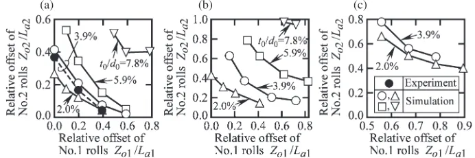
[image:5.595.126.471.71.259.2]The corner droop on this condition can not be a eliminated. Figure 14 summarizes combinations of offsets at No. 1 and 2 processes for eliminating corner droop. These have been found from 7 kinds of experiments and 261 kinds of FE simulations. The larger the ratio of thickness to outer diameter is, the larger offset is necessary to eliminate corner droop. In Fig. 14(c) for LT1/LS1=1.77, offsets to eliminate
corner droop can not been found for pipes with heavier thicknesses t0/d05.9 and 7.8%.
4. Conclusions
(1) Corner droop can be reduced by offsetting side rolls. This depends on the longitudinal contact length of top and bottom rolls.
(2) Defining the geometrical contact length by normalizing the offset by the defined contact length, it is possible tofind the optimum offset uniquely for forming conditions.
(a) (b) (c)
Fig. 10 Effect of reduction r1 on relationship between offset Zo1 and deviation of corner shape of pipe formed by No. l rolls (t0/d0=3.9l%); (a)LT1/LS1=1.27 (b)LT1/LS1=1.43 (c)LT1/LS1=1.77.
(a)
(b) (c)
Fig. 11 Effect of reduction ri on offset of rolls in case of becoming
sy¹sa=0 (t0/d0=3.9l%); (a)LTi/LSi=1.27 (b)LTi/LSi=1.43 (c)LTi/
LSi=1.77.
[image:5.595.53.282.302.566.2](a) (b)
Fig. 12 Effect of wall thicknesst0on relationship between ratio of roll diameter and corner shape of pipe formed by No. 1 rolls (r1=12.2%); (a) Average of heightsyand widthsxof corner (b) Deviation of heightsy
[image:5.595.306.547.308.460.2](3) The relative offset to eliminate the corner droop is made clear for many forming conditions. The larger the ratio of geometrical contact length of top and bottom rolls to that of side rolls is, the larger the offset becomes. The larger the reduction from the circular pipe to the square one is, the smaller it becomes. The heavier the ratio of thickness to the outer diameter of the circular pipe is, again the larger it becomes.
REFERENCES
1) M. Kiuchi, K. Shintani and M. Tozawa: J. JSTP 21(1980) 339346 (in Japanese).
2) Y. Onoda, T. Nagamachi and T. Sugiyama: J. JSTP36(1995) 149154 (in Japanese).
3) T. Nagamachi, T. Nakako and D. Nakamura:Mater. Trans.52(2011) 21592164.
4) H. Kondo, R. Takeda, K. Ohmori and N. Kunita: Kawasaki Steel GIHO
28(1996) 6975 (in Japanese).
[image:6.595.126.468.70.262.2](a) (b) (c)
Fig. 13 Effect of wall thicknesst0on relationship between offset Zo1and deviation of corner shape of pipe formed by No. 1 rolls (r1=12.2%); (a)LT1/LS1=1.27 (b)LT1/LS1=1.43 (c)LT1/LS1=1.77.
(a) (b) (c)
Fig. 14 Effect of wall thicknesst0on offset of rolls in case of becomingsy¹sa=0 (r3=19.6%); (a)LTi/LSi=1.27 (b)LTi/LSi=1.43
[image:6.595.124.470.315.430.2]