Application of Recrystallization Texture Evolution Model
to Type 430 Stainless-Steel Strip Production
Toshiharu Morimoto
1, Fuyuki Yoshida
1, Yuji Kusumoto
1, Masahiko Oda
1and Jun Yanagimoto
2 1New Product Development Department, Nakayama Steel Works, Osaka 551-8551, Japan2Institute of Industrial Science, The University of Tokyo, Tokyo 153-8505, Japan
The ridging phenomenon of type 430 stainless-steel originates from the texture due to crystal plasticity anisotropy. Thus, to predict the antiridging property, we must continuously analyze the hot-rolling, hot-rolling and annealing, cold-rolling, cold-rolling and annealing textures. However, it has been previously difficult to analyze the recrystallization texture. We thus developed a model to predict the recrystallization texture coupled with the Taylor rolling model. Furthermore, the ridging index was calculated in order to estimate the plasticity in type 430 stainless-steels. The plasticity prediction method was applied to type 430 stainless-steel strips rolled at a low temperature with a high reduction rate in an actual tandem hot strip mill. [doi:10.2320/matertrans.MA201204]
(Received March 5, 2012; Accepted June 12, 2012; Published October 25, 2012)
Keywords: recrystallization texture, rolling texture, crystal plasticity, type 430 stainless-steel, microscopic slip
1. Introduction
The thermomechanical controlled process (hereafter called the TMCP method) has been prevalent in producing fi ne-microstructure steels by optimizing the rolling temperature, rolling reduction and cooling rates. The TMCP method was developed in the 1970s to improve the low-temperature toughness of hot plates and has recently been developed both in bar rolling and in tandem hot strip rolling.1) Ferritic
stainless-steel strips are widely used in electric appliances and housing applications because of their high anticorrosion properties and attractive appearance. Ferritic stainless steels, however, exhibit a ridging phenomenon because they hardly recrystallize during hot rolling, do not undergo a phase transformation after hot rolling, and their casting structure easily remains in thefinal products.24)Thus, to improve the antiridging properties, type 430 stainless-steels were hot rolled at a low temperature with a high reduction rate in an actual tandem hot strip mill, which has rolling stands with different diameters and laminar flow cooling devices in the
final finishing stands.5)
The ridging phenomenon originates from casting colonies being formed as a result of crystal plasticity anisotropy.69)
Prediction of the antiridging properties required continuously analyzing the hot-rolling, hot-rolling and annealing, cold-rolling, and cold-rolling and annealing textures. However, it has previously been difficult to analyze the recrystallization texture.1018)Thus, a model to predict the recrystallization
tex-ture using the Taylor rolling model was developed.19,20)The
texture prediction model was then applied to a new stainless-steel strip of type 430 rolled at a low temperature with a high reduction rate in an actual tandem hot strip mill. Furthermore, the ridging index was calculated from the analyzed texture to predict the plasticity of ferritic stainless-steels.6)
2. Thermomechanical Simulator of Type 430 Stainless-Steel
To investigate the recrystallization behavior at a high temperature, a type 430 stainless-steel was hot-compressed
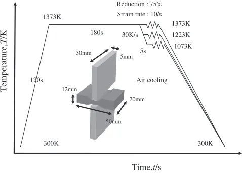
with a reduction of 75% at 1073 to 1373 K. The chemical composition was 0.06C0.25Si0.60Mn16.0Cr (mass%). Figure 1 shows the thermomechanical compression patterns under plain strain conditions. Figures 2 and 3 show strain stress curves and the microstructures at the thickness center compressed at 1073, 1223 and 1373 K, respectively. It is considered that partial recrystallization occurs in the temper-ature range from 1223 to 1373 K, but no recrystallization occurs at 1073 K, because a few small equiaxed grains were observed at 1223 and 1373 K, and the flow stress at 1073 K is much higher than those at 1223 and 1373 K. Thus, it is concluded that the type 430 steel compressed at 1073 K has a higher residual strain than those compressed at 1223 and 1373 K. Figure 4 shows inverse pole figures of the compressed type 430 compression samples obtained at the thickness center using the electron backscatter diffraction pattern method (hereafter called EBSD). Since type 430 steels do not transform, a bcc typical rolling texture is suggested. It is considered that partial recrystallization occurs either during compression or after compression at 1373 K.
Time,t/s
1373K
T
emperature,
T
/K
300K 120s
1373K
1073K Reduction : 75% Strain rate : 10/s
Air cooling
300K
180s 30K/s
5s
50mm 20mm 12mm
5mm 30mm
1223K
Fig. 1 Thermomechanical compression pattern and plain strained piece. Special Issue on Crystallographic Orientation Distribution and Related Properties in Advanced Materials III
[image:1.595.308.547.316.487.2]3. Actual Rolling and Mechanical Properties of Type 430 Stainless-Steel
Tables 1 and 2 show the rolling conditions in the actual tandem hot strip mill. The chemical composition was 0.06C 0.25Si0.60Mn16.0Cr (mass%), the thickness of the slab was 250 mm. The slab was reheated at 1433 K and roughly rolled into a hot bar with a 36.5 mm thickness in seven passes andfinish-rolled into a hot strip with a 3 mm thickness in six
passes. The two kinds offinishing schedules were employed, although the roughing conditions were the same for both types. Thefinal three rolling reductions of the rougher were 27.0%(R5), 31.6%(R6) and 28.6%(R7), and the roughing delivery temperature was 1293 K. The texture at the thickness center of the rough-rolling bar by the EBSD is shown in Fig. 5. Generally, the type 430 steel produced by rough-rolling at a high temperature with a high reduction rate can recrystallize. The finishing delivery temperature for case 1
0 50 100 150 200 250 300
0 0.3 0.6 0.9 1.2 1.5
True strain,
ε
T
rue stress,
σ
/MP
a
1373K 1223K 1073K
1073K
1373K
1273K Strain rate 10/s
Fig. 2 Strainstress curve of type 430 stainless-steel.
Fig. 3 Microstructure of type 430 stainless-steels by thermomechanical compression.
1373K 1073K
ND ND
[image:2.595.69.269.70.250.2]Fig. 4 Inverse pole figures of type 430 stainless-steel at the thickness center by thermomechanical compression.
Table 1 Roughing roll schedule of type 430 stainless-steel at the tandem hot strip mill.
R1 R2 R3 R4 R5 R6 R7 Reheated
temp. (K)
Roughing delivery temp. (K) Thickness
(mm) 211.1 172.8 136.6 102.4 74.8 51.2 36.5
1433 1293
Reduction
(%) 16.0 18.2 20.9 25.0 27.0 31.6 28.6
Rolling
velocity (m/s) 1.99 2.52 3.2 3.53 3.93 4.44 4.61
Interval time between rolls (s)
12 12 12 13 13 15 20*
[image:2.595.305.549.70.231.2] [image:2.595.105.491.302.430.2] [image:2.595.44.549.487.639.2]was 1238 K and that for case 2 was 1100 K, that is, case 1 was a high-reduction rate high-temperature rolling, while case 2 was a high-reduction rate low-temperature rolling in the finishing train. The rolling reduction of the last three stands in thefinishing train were 31.7%(F4), 27.7%(F5) and 25.3%(F6). Rolling strips were cooled by air on the run out table and coiled.
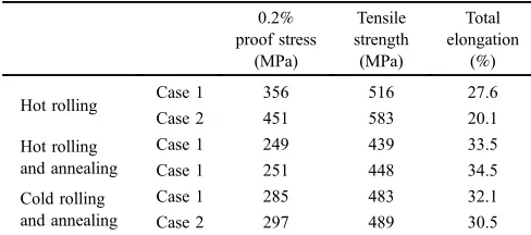
Figure 6 shows the microstructure of the hot strips for the two cases obtained at the thickness center. The grains in case 2 were more elongated than those in case 1. Table 3 shows the mechanical properties of the hot strips. The tensile strength for case 2 was higher than that for case 1, because the hot strip in case 2 should have more residual dislocations than in case 1. It was confirmed that the case 2 strip has more residual strain than the case 1 strip using the half-width values of the X-ray diffraction, as shown in Fig. 7. Half-width value of case 1 and case 2 were 0.0104 and 0.0123 radians, respectively.
Next, the hot strips both in case 1 and case 2 were annealed at 1123 K for 8 h and cold-rolled to a thickness of 0.5 mm, then annealed at 1193 K for 2 min. Figure 6 and Table 3 show the microstructures and mechanical properties of the annealing hot and cold bands, respectively. For both bands, the tensile strength for case 1 was lower than that for case 2. It is concluded that the grains for case 1 recovered more rapidly than those for case 2 because the residual strain of the hot-rolling strips for case 1 was lower than that for case 2, as shown in Fig. 7. Moreover, after cold-rolling and annealing, the recrystallized grains in case 1 grew faster than
those in case 2. The ridging values of the cold-rolling and annealing strips are shown in Table 4 and Fig. 8. Ridging density is the number of ridging in 20 mm length. The antiridging property in case 2 was superior to that in case 1. As the ridging density was inversely proportional to the grain size, the ridging in case 1 was steeper than that in case 2.
Fig. 5 Polefigures of type 430 stainless-steel rough rolling bar at the thickness center. Table 2 Finishing roll schedule of type 430 stainless-steel at the tandem hot strip mill.
F1 F2 F3 F4 F5 F6
Finishing delivery temp. (K)
Coiling temp. (K)
Case 1 Thickness (mm) 19.9 13.0 8.2 5.6 4.1 3.0 1238 1101
Reduction (%) 45.0 35.0 36.5 31.7 27.7 25.3
Case 2 Thickness (mm) 19.9 13.0 8.2 5.6 4.1 3.0 1100 1005
Reduction (%) 45.0 35.0 36.5 31.7 27.7 25.3
Rolling velocity (m/s) 1.39 2.23 3.44 5.94 8.46 9.98 *7.5 s means that
transferring time from finishing roll to coiling. Interval time between
[image:3.595.54.532.87.400.2]rolls (s) 3.9 2.5 1.6 0.9 0.7 7.5*
Table 3 Mechanical properties of type 430 hot rolling, hot rolling and annealing and cold rolling and annealing.
0.2% proof stress
(MPa)
Tensile strength (MPa)
Total elongation
(%)
Hot rolling Case 1 356 516 27.6
Case 2 451 583 20.1
Hot rolling and annealing
Case 1 249 439 33.5
Case 1 251 448 34.5
Cold rolling and annealing
Case 1 285 483 32.1
[image:3.595.85.512.254.398.2]Case 2 297 489 30.5
Table 4 Formability of type 430 stainless-steel cold band annealed. Ridging
height (µm)
Ridging density (/20 mm)
Average Lankford value
Grain size (µm)
Case 1 18.2 21.3 1.16 16.7
[image:3.595.304.548.467.575.2] [image:3.595.304.549.619.675.2]4. Analyses of Rolling and Recrystallization Textures
4.1 Taylor rolling model
In this study, we made the following assumptions in the rolling texture analysis. The critical shear stress for all slip systems was the same and calculated from the equivalent
flow stress divided by the Taylor Factor. The equivalentflow
Fig. 6 Optical microstructure of type 430 stainless-steel hot-rolling, hot-rolling and annealing, cold-rolling and annealing strips.
0 5000 10000 15000 20000 25000 30000
2.68 2.70 2.72 2.74
Diffraction angle,2 /radian
Dif
fraction intensity
,
c
/counts
case1 case2
θ
Fig. 7 X-ray diffraction pattern of type 430 stainless-steel hot-rolling strip at the thickness center.
-30 -20 -10 0 10 20 30
0 5 10 15 20
Tranverse direction,
x
/mm
Ridging height,
h
/μ
m
-30 -20 -10 0 10 20 30
0 5 10 15 20
Transverse direction,
x
/mm
Ridging height,
h
/μ
m
(a)
(b)
[image:4.595.122.477.66.456.2] [image:4.595.321.533.493.760.2] [image:4.595.78.260.494.653.2]stress was analyzed from the measured rolling load using the Orowan rolling theory model.21)
Hereafter,Xi(i=1, 2, 3) is the vector component of Xin an orthogonal coordinate system. The displacement velocity vectoru_ can be expressed as
_
u¼£_ðxaÞb; ð1Þ
where, £_,x,a and b are the slip rate, the position, the unit vector normal to the slip plane and the unit vector in the slip direction, respectively. Thus, the plastic strain rate DP and plastic spin WP can be defined using eqs. (2) and (3), respectively.
Dijp¼
1 2
@u_j
@xi
þ@u_i
@xj
¼1
2£_ðaibjþajbiÞ ¼Pij£_: ð2Þ
WijP¼
1 2
@u_j
@xi
@u_i
@xj
¼1
2£_ðaibjajbiÞ ¼Qij£_; ð3Þ
where Pij¼
1
2ðaibjþajbiÞ ð4Þ
Qij¼
1
2ðaibjajbiÞ: ð5Þ
where, the plastic strain rate DP¥Dis calculated using the Orowan rolling theory model.
The b.c.c. crystal lattice has 12f110gh111islip systems, 12
f112gh111islip systems and 24f123gh111islip systems. The strain equilibrium, the shear stress of each slip system, the rate-dependent rule and boundary condition are expressed using eqs. (6)(9), respectively. Equation (6) implies that the sum of the slip values £j multiplied by Pij for each slip
system in a crystal is equal to the sum of the microstrains¾. Equation (7) gives the relationship between the microstress
· and the resolved shear stress¸ acting on the slip plane. Equation (8) is the Asaro rate-dependent rule and m is a material parameter.22) For the boundary conditions, the
microstrain ¾ is assumed to be equal to the macrostrain E
in accordance with the Taylor theory, as shown in eq. (9).
d¾i¼XPijd£j ð6Þ
¸j¼XPij·i ð7Þ
d£j¼£_0dt ¸j¸
y 1=m
signð¸jÞ ð8Þ
"¼E ð9Þ
where, £_0, ¸y and dt are the reference slip strain rate, the
critical shear stress and the time increment, respectively. The critical shear stress¸y can be expressed as
¸y¼S=TF ð10Þ
where TF is the average Taylor Factor for all orientations. The Taylor Factor was calculated under plain strain conditions, thus macrostrain tensorEwas explained below.
E¼
¾xx ¾xy 0 ¾xy ¾xx 0
0 0 0
0 B @ 1 C A ð11Þ
wherex,y,zwas the rolling direction, the thickness direction and the width direction, respectively.Sis the equivalentflow stress, which was determined from the measured rolling force using the Orowan rolling theory model. The initial Taylor factor of b.c.c. crystals T F0 is 2.75.23)
On the basis of Lee’s elastic-plastic decomposition of a deforming material,24)the deformation gradient tensorFand
velocity gradient tensorLof a crystal can be expressed using the following equations.
F¼RU ð12Þ
L¼DþW ð13Þ
where,R,U,Dand Ware the rotation tensor, stretch tensor, strain rate tensor, and total spin tensor, respectively.DandW
are calculated using the Orowan model.19)
As a result, the lattice rotation spin tensor is indicated by eqs. (14) and (15).
¼WWP ðW¼0Þat the center ð14Þ ¼WWP at the surface ð15Þ
The rotation tensor R is obtained using eqs. (16) and (17).
Iis the identity tensor.
_
R¼R ð16Þ
R¼expdtIþdtþ1=2dt22 ð17Þ
The parameters of the Asaro rate-dependent rule are the same as in our previous report.19)£_0is 100 andmis 0.05.
4.2 Recrystallization model
We introduced conventional assumptions to predict the recrystallization texture based on the preferential orientation model.10) Nucleation occurs from piled-up dislocations at
grain boundaries and the recrystallized grains have the same orientations as deformed grains. The number of microscopic slips is equal to the number of dislocations, as shown by
d£ ¼µbx: ð18Þ
where d£, µ, b and x are the incremental slip value, the number of dislocations, the burgers vector and the displace-ment, respectively. Thus, the total number of microscopic slips¥is estimated as the total number of dislocations piled up at the grain boundaries as described by
¼Xd£i: ð19Þ
For prediction of the recrystallization texture, the following assumptions are introduced. First, as the hot rolling and annealing, grains with a small total number of microscopic slips might obtain a preferred orientation. Second, as the cold rolling and annealing, grains with a high total number of microscopic slips might obtain a preferred orientation. The
first assumptions were valid as indicated in our previous report.20) These assumptions were introduced for the static
recrystallization in the interval of hot-rolling. High temper-ature uniaxial compression of Fe3%Si alloy showed that
Calculation step was one-fiftieth of rolling time. The Taylor Factor in eq. (10) was updated once a calculation step was completed to reflect the texture evolution. As type 430 stainless steel hardly dynamically recrystallized during hot-rolling, dynamic recrystallization ratio assumed to be zero in this model.
4.3 Application of recrystallization texture model to actual rolling
First, the type 430 stainless-steel hot-rolling texture of the
finishing roll schedule shown in Table 2 was analyzed. The steel,finish rolled at a high temperature with a high reduction rate as case 1 can recrystallize at the intervals of each rolling pass. On the other hand, the steel for case 2, finish rolled at a low temperature with a high reduction rate cannot recrystallize. Kimura proposed a static recrystallization rate for ultralow-carbon ferritic stainless steel as4)
t0:5¼8:41011d0¾1:5¾_0:4expðQ=RTÞ ð20Þ
wheret0.5,d0,¾and¾_are the 50% recrystallization time, the
initial grain size, the equivalent strain and the equivalent strain rate, respectively. Q (200 kJ/mol), R and T are the activation energy, the gas constant and the temperature, respectively. The static recrystallization ratios of each stand are shown in Fig. 10. Figure 11 shows the observed and analyzed hot-rolling textures for case 1 and 2 using the recrystallization model coupled with the Taylor rolling texture model. There was a slight difference between the predicted and measured textures. Although the grain size was assumed to be equal in our texture model, the recrystallized
grains were smaller than the deformed non-recrystallized grains, and grain size could affect the polefigures measured by the EBSD. Furthermore, crystal rotation in the polycrystal model was more promoted than in actual rolling because of no grain boundary restriction.26)
Figure 12 is histograms of the total number of microscopic slips for about 4000 grains in the finished rolling schedule shown in Table 2, calculated by the recrystallozation texture evolution model. A horizontal unit in the histogram is one microscopic slip in the slip system. The total number of microscopic slips for case 2 was higher than that for case 1. Final total number of microscopic slips assumed to be
Hot-rolling texture model start
Initial orientation Asaro’rule parameter Initial Taylor factor Calculation time step
(
n n n)
2 1,Φ ,φ
φ 0 ,γ m 0 TF
Equivalent flow stress Macro strain Total spinE
S Rolling
condition
Slip direction Normal to slip plane Schmid tensor a b Orowan Rolling Model Taylor Texture Model Total Grain Number N n=1
Q P,
Critical shear stress
TF S
y= /
τ
Slip value Plastic strain Shear stress Plastic spin
ε P
W
Lattice rotation spin Rotation tensor R
Ω
dγ
Increment of Euler angle
(
d n d n d n)
2 1, Φ , φ
φ
Rolling texture
Total microscopic slip n dγn
∑ = Γ
(
n n n)
2 1,Φ ,φ
φ
τ
Boundary condition E =ε
Taylor Texture Model t Δ Slip system
Average Taylor factor for all orientations TF W Total Number of Microscopic Slip Recrsystallized Texture Model
Hot-rolling texture model end Number of recrystallized grain
Grain of small total slips Grain of large total slips
x n
Update Euler angle (Recrystallized texture) x y n n 1 1 φ
φ = Φny=Φnx ny nx
2 2 φ φ = y n y x NXS= =
Dynamic Recrytallized Ratio Static Recrystallized Ratio D X S X ) X ( D 0
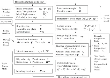
Fig. 9 Flow chart of hot-rolling texture calculation model.
0 0.2 0.4 0.6 0.8 1
F1 F2 F3 F4 F5 F6
Finishing stand number
Static recrystallization ratio
[image:6.595.87.512.72.374.2]Case 1 Case 2
[image:6.595.336.519.422.596.2]residual strains. Therefore, more strain was observed in the case 2 rolling strip than in the case 1 rolling strip. To make type 430 stainless-steel strips exhibit good antiridging properties, they should have a nearly random orientation after cold-rolling and annealing. Thus, recrystallization for case 1 and 2 were investigated to affect final orientation by the recrystallization texture evolution model. In the case 1,
rolling with a high reduction rate at a high temperature made recrystallization at the intervals of each rolling pass. In the case 2, rolling with a high reduction rate at a low temperature accumulated strains which made recrystallization during hot band annealing.
Second, grains of 10% low ranks in the total number of microscopic slips were selected from Fig. 12. Third, the
cold-Fig. 11 Hot rolling texture predictions of case 1 and case 2 in the type 430 stainless-steel.
0 100 200 300 400 500 600
0 0.7 1.4 2.1 2.8 3.5 4.2 4.9 5.6 6.3 7
Total amount of microscopic slips
Frequenc
y
0 100 200 300 400 500 600
0
0.7 1.4 2.1 2.8 3.5 4.2 4.9 5.6 6.3 7
Total amount of microscopic slips
Frequenc
y
[image:7.595.84.510.65.469.2](a) (b)
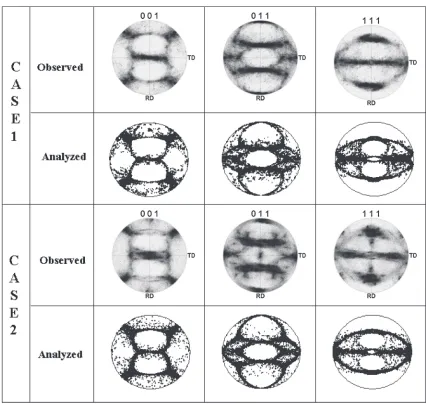
[image:7.595.89.512.522.656.2]rolling texture was calculated by the Taylor rolling model whose initial texture was the predicted hot-rolling and annealing one. Finally, grains of 10%high ranks in the total number of microscopic slips were selected. Figure 13 shows the predicted texture of the cold-rolling and annealing strip by the continuous texture prediction method.20)Although this
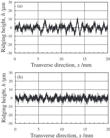
recrystallization model was the first approximation, predic-tion accuracy was qualitatively good. However, many problems exit in this model. For example, it’s not considered that grain growth affects crystal orientation. Furthermore, this model might be useful to texture evolution of only the b.c.c. crystals because the f.c.c. crystals sometime cross slip or twin. Figure 14 shows the ridging height obtained by the Wu method,6)which indicated thickness direction strain distribu-tion after being 15% stretched. Standard deviation of case 1 was 0.014 and of case 2 was 0.012. Thus, the calculated ridging height for case 2 was slightly better than that for case 1. While, measured ridging height of case 1 was 18.2 µm and of case 2 was 12.1 µm. Thus, our ridging prediction accuracy was underestimated. However, the developed texture prediction model is useful to optimize the best rolling condition and to predict the ridging properties for the type 430 stainless-steel strips.
C
A
S
E
2
C
A
S
E
1
Observed
Analyzed
Observed
[image:8.595.86.512.66.470.2]Analyzed
Fig. 13 Cold band annealing texture prediction in case 1 and case 2 in type 430 stainless-steel.
-0.2 -0.1 0 0.1 0.2
Length,
x
/mm
Calculated ridging heigh,
h
2.5 0.0
-0.2 -0.1 0 0.1 0.2
Length,
x
/mm
Calculated ridging height,
h
2.5 0.0
(a)
(b)
[image:8.595.325.529.499.761.2]5. Discussion
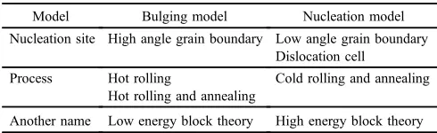
We propose two recrystallization models based on the total number of microscopic slips. The preferential recrystalliza-tion orientarecrystalliza-tion that is the same as that of the grains with a small total number of microscopic slips indicates bulging at a high-angle grain boundary.27) On the other hand, the
preferential recrystallization orientation that is the same as that of the grain with a high total number of microscopic slips indicates nucleation at a low-angle grain boundary.28,29) To explain the difference in the two recrystallization models, the misorientation distributions calculated by the Taylor rolling model are shown in Fig. 15. There are two groups of misorientations namely, the low-angle and high-angle misorienation groups shown in Table 5. Bulging at a high-angle grain boundary means a low-energy block theory. While, nucleation at a low-angle grain boundary means a high-energy block theory, which nucleates from dislocation cell. During hot-rolling, dislocation density is low and
strain-induced grain migration occurs, while during cold-rolling with relatively high reduction, dislocation density is high and dislocation cell structures are produced. Then, as annealing the cold-rolled strip, dislocations decrease, rearrange and dislocation cell structure becomes to be sub-grains.30,31) Many researchers have reported both high- and low-energy block theories and we suggest that both theories are valid.
6. Conclusion
We developed a new ferritic stainless-steel strip (type 430) with antiridging properties by high-reduction low-temper-ature rolling in a tandem hot strip mill, and the prediction accuracy of the texture and formability from a hot rolling schedule to a cold rolling schedule through our texture evolution model was confirmed qualitatively. Finally, two recrystallization models, namely, bulging at a high-angle boundary and nucleation at a low-high-angle boundary, were suggested in hot-rolled and cold-rolled materials, respectively.
REFERENCES
1) J. Yanagimoto, T. Morimoto, R. Kurahashi and I. Chikushi: Steel Res. Int.73(2002) 5662.
2) H. Takechi, H. Kato, T. Sunami and T. Nakayama: Trans. JIM8(1967) 233239.
3) T. Sakai, Y. Saito and M. Matsuo:ISIJ Int.31(1991) 8694. 4) K. Kiumura and A. Takahashi: Nippon Steel Technical Report 389
[image:9.595.103.487.68.396.2](2009) 5155.
Fig. 15 Stable orientation and misorientation histogram using rolling texture analysis model.
Table 5 Distinction of two recrystallization models.
Model Bulging model Nucleation model
Nucleation site High angle grain boundary Low angle grain boundary Dislocation cell
Process Hot rolling
Hot rolling and annealing
Cold rolling and annealing
[image:9.595.46.291.456.531.2]5) T. Morimoto, T. Mukaihara, Y. Kusumoto, M. Oda, K. Takeshima and H. Yatoh:Steel Res. Int.82(2011) 155163.
6) P. D. Wu, H. Jin, Y. Shi and D. J. Loyd:Mater. Sci. Eng. A423(2006) 300305.
7) M. Brouchu, T. Yokota and S. Satoh:ISIJ Int.37(1997) 872877. 8) H. J. Shin, J. K. An, S. H. Park and D. N. Lee:Acta Mater.51(2003)
46934706.
9) I. Jung, J. Mola, D. Cooman and D. Chae:Steel Res. Int.81(2010) 10891096.
10) W. G. Burgers and T. J. Tiedma:Acta Metall.1(1953) 234238. 11) I. L. Dillamore, P. L. Morris, C. J. E. Smith and W. B. Hutchinson:
Proc. R. Soc. Lond. A329(1972) 405420. 12) W. B. Hutchinson: Metal Sci.8(1974) 185196. 13) O. Akisue: J. Jpn. Inst. Met.40(1976) 206210. 14) W. B. Hutchinson: Int. Metals Rev.29(1984) 2542. 15) O. Akisue: Tetsu to Hagane72(1986) 13201327.
16) J. J. Jonas and L. S. Toth:Scr. Metall.27(1992) 15751580. 17) T. Urabe and J. J. Jonas:ISIJ Int.34(1994) 435442.
18) M. Muraki, T. Toge, K. Sakata, T. Obara and E. Furubayashi: Tetsu to
Hagane85(1999) 751757.
19) T. Morimoto, F. Yoshida, Y. Kusumoto and O. Akisue: ISIJ Int.50
(2010) 16831688.
20) T. Morimoto, F. Yoshida, Y. Kusumoto and A. Yanagida:ISIJ Int.52
(2012) 592600.
21) E. Orowan:Proc. Inst. Mech. Eng.150(1943) 140146. 22) R. J. Asaro and A. Needleman:Acta Metall.33(1985) 923953. 23) J. M. Rosenberg and H. R. Piehler:Metall. Mater. Trans. B2(1971)
257259.
24) E. H. Lee:J. Appl. Mech.36(1969) 16.
25) Y. Onuki, K. Okayasu and H. Fukutomi:ISIJ Int.51(2011) 15641565. 26) H. Takahashi, M. Mashiko, H. Motohashi and S. Tsuchida: J. J.S.M.E.
A60(1994) 12101215.
27) I. L. Dillamore and H. Katoh: Metal Sci.8(1974) 7383. 28) C. G. Dunn:Acta Metall.1(1953) 163175.
29) Y. C. Liu and W. R. Hibbard: J. Metals7(1955) 381386.
30) J. Takamura: Zairyokyodonokiso, (Kyoto University Press, Kyoto, 2003) pp. 278280.