Alignments and Orientations of MnSn
2Phase during the Solidi
fi
cation Process of
Sn
Mn Alloy under a High Magnetic Field
Lei Li
1,2,+, Yuantong Bi
1,2,+, Hui Zhang
1,2and Jianzhong Cui
1,21Key Laboratory of Electromagnetic Processing of Materials, Ministry of Education, Northeastern University, Shenyang, 110819, PR China 2School of Materials Science and Engineering, Northeastern University, Shenyang, 110819, PR China
It has been reported that MnSn2exhibited unusual magnetic behaviors related to its crystal structure. However, little work has been done to
investigate its behavioral responses to a high magneticfield (HMF), which is of potentially fundamental interest. Based on this, binary SnMn alloy was solidified under different HMFs in this work. The results show that the primary MnSn2crystals appear block- or bar-like shapes in both
the longitudinal and transverse sections. In the longitudinal sections, however, the HMFs tend to align the bar-like crystals with the long axes perpendicular to the magneticfield. In the transverse sections, the HMFs have little influence on the alignments of the bar-like crystals but increase their amount. A crystallographic study indicates that ©110ª is the easy magnetization axis of the MnSn2 crystals that orients
preferentially parallel to the magneticfield. These results are attributed to the magnetic anisotropy of the MnSn2crystals. [doi:10.2320/matertrans.M2019030]
(Received January 28, 2019; Accepted March 28, 2019; Published May 25, 2019)
Keywords: high magneticfield, solidification, primary MnSn2phase, alignment, orientation
1. Introduction
As a CuAl2-type intermetallic compound, MnSn2has ever
aroused great interest of researchers due to its unusual magnetic behaviors in the 1960s. Kouvel and Harteliusfirstly reported that the magnetic susceptibility of MnSn2decreased
precipitously as the temperature was lowered through 73 K.1)
Yasukōchi et al. found that the MnSn2 exhibited an
antiferromagnetic behavior with a Néel temperature of 324 K.2) Later, Corliss and Hastings made a neutron
diffraction study and further demonstrated its antiferromag-netism above the abrupt transition at 73 K.3)These behaviors
are all related to its tetragonal C16 structure, which consists of alternating layers of Mn and Sn perpendicular to the c-axis.3) Moreover, in the MnSn2 structure, c-axis (c=
5.447¡) is much shorter than the a-axis (a=6.659¡),4) suggesting a strong crystal structure anisotropy. This may also imply a strong magnetic anisotropy. Considering these magnetic properties, it is of potentially fundamental interest to investigate its behavioral responses to a high magnetic
field (HMF).
Solidification of metallic alloys in a HMF is always a hot topic ever since the development of superconducting magnet technology. Numerous experimental works have demon-strated that the HMFs present a significant influence on the growth of crystals.517)For example, the HMFs could orient and align the crystallizing phases,59)promote the structural homogenization,10,11) result in the modification of structure
morphology,1214) and induce the breakdown of a planar interface into cellular undulations,15) etc. Among these effects, the orientations and alignments are directly related to the magnetic properties of the crystals and have been extensively investigated. Mikelson and Karklin obtained aligned structures in AlCu and CdZn alloys under a 1.5 T magnetic field.5) Morikawa et al. reported a perpendicular
alignment of the intermetallic compounds in AlSiFe alloy under a 5 T HMF.6) Li et al. found a ©001ª preferential
orientation of the Al3Ni crystals in AlNi alloy under a 10 T
HMF.7)Liuet al.showed that the c-plane of MnSb crystals in MnSb alloy oriented parallel to the 11.5 T HMF.8)Based on these results, the investigation on the behavioral responses of the MnSn2 phase to the HMF can be carried out in the
solidification process of binary SnMn alloy.
In view of such background, binary Sn1.5 wt%Mn alloy was solidified under different HMFs in this work. The effects of the HMF on the alignments and orientations of the MnSn2
phase were systematically studied based upon the Electron Backscatter Diffraction (EBSD) technique. And the mechan-ism leading to the modification of the alignments and orientations were also discussed briefly.
2. Experimental Procedure
Pure metals of Sn (99.95 wt%) and Mn (99.9 wt%) were melted in an induction furnace under argon atmosphere to prepare the Sn1.5 wt% Mn alloy. After degassing and deslagging, the melt was poured into a high-purity copper mould to solidify rapidly into several ingots () 10© 100 mm). Six small round rods (¯10©12 mm) were further cut from these ingots for the subsequent HMF experiments.18)
The experimental setup has been introduced elsewhere in detail. A rod was put into a tube of high-purity corundum crucible and then placed in the center of the resistance furnace, where a maximum axial magnetic flux density B of 12 T could be produced. After the magneticfield reached the set value (0, 1, 3, 5, 8.8 and 12 T, respectively), the rod was heated up to 380°C at a rate of 5°C/min under argon atmosphere. After being held at this temperature for 20 min, the melt was furnace-cooled to room temperature (the average cooling rate was about 6°C/min).
The HMF-treated as-cast ingots ()10©12 mm) were cut longitudinally and then transversely (parallel and perpendic-ular to the HMF direction B, respectively), following a standard mechanical polishing. The microstructures of the specimens were observed by a Zeiss ULTRA PLUS FE-SEM (Field-Emission Scanning Electron Microscope, Carl Zeiss,
+Corresponding author, E-mail: lilei@epm.neu.edu.cn Materials Transactions, Vol. 60, No. 6 (2019) pp. 939 to 943
Jena, Germany). After further polishing and argon ion beam cleaning, EBSD (Electron Backscatter Diffraction) orienta-tion measurement was performed on the specimens for crystallographic analysis by the same FE-SEM (equipped with an Oxford-HKL Channel 5 system) as above.
3. Results and Discussions
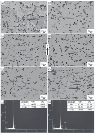
Figures 1(a)(f ) show the microstructures in the longi-tudinal sections of the Sn1.5 wt% Mn specimens under different HMFs, respectively. An EDS analysis indicates that the light gray part represents the ¢-Sn matrix while the dark gray part the primary MnSn2phase, as evidenced by the
spectrums in Figs. 1(g) and (h), respectively. It is observed from Figs. 1(a)(f ) that the primary MnSn2 crystals appear
block- or bar-like shapes in all cases. However, the alignments of the bar-like primary MnSn2 crystals alter as
the HMFs increase, i.e. the long axes tend to align perpendicular to the magneticfield directionB.
To fully understand the morphological variation of the primary MnSn2 phase, Fig. 2 shows the microstructures in
the transverse sections of the specimens under different HMFs, respectively. It is obvious that the bar-like primary MnSn2 crystals align randomly in all cases, irrespective of
whether the HMFs are applied or not. As the HMFs increase, however, the amount of the block-like primary MnSn2
crystals decreases while that of the bar-like ones increases. In our previous work, we have shown that a typical MnSn2
crystal follows an octagonal-base/spherical-cap geometric model (few possess square bases) in three dimensions.19)And
such anisotropic shape is kinetically related to its anisotropic crystal structure. Therefore, the HMF-induced alteration to the alignments of the MnSn2 crystals in this work should
be accompanied by modification of the crystallographic
Fig. 1 Longitudinal microstructures of the Sn1.5 wt%Mn specimens with the application of (a) 0 T, (b) 1 T, (c) 3 T, (d) 5 T, (e) 8.8 T and (f ) 12 T HMFs, respectively; EDS spectrums corresponding to the (g)¢-Sn matrix and (h) primary MnSn2phase, respectively. The arrow
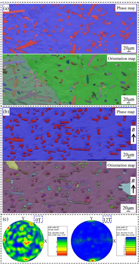
[image:2.595.138.459.68.519.2]orientations. To demonstrate this, a crystallographic analysis was carried out. Figures 3(a) and (b) show the EBSD phase (red - MnSn2; blue -¢-Sn) and orientation maps
correspond-ing to the longitudinal microstructures without and with the 12 T HMF, respectively. In the phase maps, the alignment difference of the bar-like primary MnSn2crystals can still be
clearly observed. In the orientation maps, however, they reveal various colors in both cases, suggesting different crystallographic orientations of them. Tofind more crystallo-graphic information, Fig. 3(c) shows the contoured ©110ª direction polefigures corresponding to the MnSn2crystals in
Figs. 3(a) and (b), respectively. The images to the right of the pole figures display the multiples of uniform densities (MUD) in different colors. In the absence of the HMF, some strong poles are randomly distributed in the X-Y coordinate system. And the maximum MUD corresponding to the strongest pole is 3.78. When the 12 T HMF is applied, a strong pole with the maximum MUD of 25.82 emerges in the Y direction (parallel to the HMF directionB). This suggests that the primary MnSn2crystals tend to orient preferentially
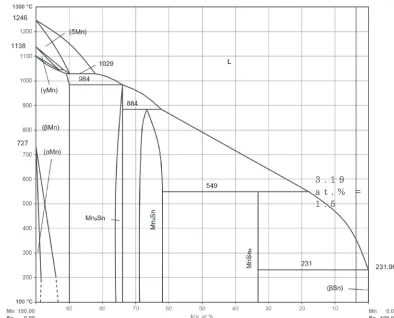
with the ©110ªdirection parallel to the magneticfield. From the binary SnMn phase diagram in Fig. 4,20)it can
be known that MnSn2crystals are crystallized primarily from
the Sn1.5 wt% Mn melt (see the vertical line that indicates this composition) when the temperature drops to the liquidus. In the absence of the HMF, they nucleate and grow freely in the two-phase region (MnSn2+liquid). Thus, they orient and
align randomly in thefinal solidification structure (Fig. 1(a)). When a HMF is employed, however, the MnSn2crystals will
be subjected to an external magnetic torque due to the magnetic anisotropy. As analysed elsewhere in detail,16,19)the
magnetization energyUi(per unit volume) of an anisotropic
crystal induced by a magneticfield can be expressed as Ui¼ »iB2=2®0ð1þN»iÞ2 ð1Þ
where the subscript i denotes the crystal i-direction, »is the magnetic susceptibility, ®0 the permeability in vacuum and
N the demagnetization factor. From this equation, it can be inferred that the easy magnetization axis tends to orient parallel to the magneticfield for paramagnetic materials (»> 0) and perpendicular to the magnetic field for diamagnetic materials (»<0) in order that the Uireaches the minimum.
As aforementioned, MnSn2 exhibits antiferromagnetism
with a Néel temperature of 324 K (about 51°C).2)It is known that antiferromagnetic materials will become typically paramagnetic above the Néel temperature. In this work, even the solidus temperature (231°C) at which the growth of the primary MnSn2 crystals ends is much higher than the Néel
temperature. Therefore, the primary MnSn2 crystals should
exhibit paramagnetism in the two-phase region. As analyzed above, the 12 T HMF tends to orient the paramagnetic primary MnSn2 crystals preferentially with the ©110ª
Fig. 2 Transverse microstructures of the Sn1.5 wt%Mn specimens with the application of (a) 0 T, (b) 1 T, (c) 3 T, (d) 5 T, (e) 8.8 T and (f ) 12 T HMFs, respectively.
Fig. 3 EBSD phase (red - MnSn2; blue - ¢-Sn) and orientation maps corresponding to the longitudinal microstructures with (a) 0 and (b) 12 T HMF, respectively; Contoured©110ªdirection polefigures corresponding to the MnSn2crystals in Figs. 3(a) and (b), respectively.
[image:3.595.306.548.68.530.2] [image:3.595.49.290.68.313.2]direction parallel to the magnetic field. Therefore, ©110ª should be the easy magnetization axis of the primary MnSn2
crystals. Hence, when the initially nucleated crystal deviates from the preferred orientations under a HMF, magnetic torqueTqwill be induced to rotate them until the©110ªaxes
are parallel to the magneticfield, which is usually expressed as21)
Tq¼V»B2sin 2ª=2®0; ð2Þ where V is the volume of the crystal, ¦» the magnetic susceptibility difference between the easy and the difficult magnetization axes and ª the angle between the applied magnetic field direction and the easy magnetization axis. Once the rotation starts, however, resistances resulting from Lorentz force and liquid viscosity will be induced to hinder the rotations. Additionally, the MnSn2crystals should reach a
critical size to overcome the disturbance effect of Brownian motion, and have enough time tofinish their rotations before the surrounding melt is completely solidified. Only when the applied HMFs are strong enough to overcome all these unfavorable factors, preferential orientations and regular alignments of the primary MnSn2 crystals can be obtained
in thefinal solidification structure. In this work, it seems that an 8.8 T HMF should be strong enough as the long bar-like MnSn2crystals already align quite regularly (see Fig. 1(e)).
To more visually exhibit the effect of the HMF, Fig. 5(a) and (b) schematically show the 3D alignments of the primary MnSn2crystals without and with the 12 T HMF, respectively
(see Ref. 19) for more information about the 3D morphology of a single MnSn2 crystal). From these two schemes, it can
be understood that the two-dimensional shapes of the primary MnSn2 crystals strictly depend on their crystallographic
orientations with respect to the observation sections. In the absence of the HMF, both block- and bar-like MnSn2crystals
will appear in the transverse section due to their random orientations. When the 12 T HMF is applied, it is natural that bar-like ones will dominate the transverse section. This just accounts for the fact that the amount of the block-like primary MnSn2 crystals decreases while that of the bar-like
ones increases with increasing the HMFs.
4. Conclusion
The effects of HMFs on the alignments and orientations of
Fig. 5 Schematic diagrams showing the 3D alignments of the primary MnSn2crystals (a) without and (b) with the 12 T HMF, respectively. The
HMF directionBis parallel to the axis of the cylinder.
3 . 1 9 a t . % = 1 . 5
[image:4.595.100.494.67.385.2] [image:4.595.303.548.424.563.2]the primary MnSn2crystals during the solidification process
of binary SnMn alloy were investigated, and it was found that:
(1) Irrespective of whether the HMFs are applied or not, the primary MnSn2 crystals appear block- or bar-like
shapes in both the longitudinal and transverse sections. (2) In the longitudinal sections, the bar-like crystals tend to align with the long axes perpendicular to the magnetic
field as the HMFs increase; In the transverse sections, the bar-like crystals align randomly in all cases, but their amount increases with increasing the HMFs. (3) The HMFs tend to orient the primary MnSn2 crystals
preferentially with the ©110ª direction parallel to the magnetic field (i.e. ©110ª is the easy magnetization axis).
(4) The above HMFs-induced alteration to the alignments and orientations is related to the magnetic anisotropy of the primary MnSn2 crystals.
Acknowledgments
This work was supported by the National Natural Science Foundation of China [grant numbers 51874092 and 51690161], and the Fundamental Research Funds for the Central Universities [grant number N180905009].
REFERENCES
1) J.S. Kouvel and C.C. Hartelius:Phys. Rev.123(1961) 124125.
2) K. Yasukōchi, K. Kanematsu and T. Ohoyama:J. Phys. Soc. Jpn.16
(1961) 11231130.
3) L.M. Corliss and J.M. Hastings:J. Appl. Phys.34(1963) 1192.
4) E.E. Havinga, H. Danmsma and P. Hokkeling:J. Less-Common Met.
27(1972) 169186.
5) A.E. Mikelson and Y.K. Karklin:J. Cryst. Growth52(1981) 524529.
6) H. Morikawa, K. Sassa and S. Asai:Mater. Trans. JIM39(1998) 814 818.
7) X. Li, Z.M. Ren and Y. Fautrelle:J. Cryst. Growth310(2008) 3488 3497.
8) T. Liu, Q. Wang, C. Zhang, A. Gao, D.G. Li and J.C. He:J. Mater. Res.
24(2009) 23212330.
9) T. Kuribayashi, S. Mun-Gyu, T. Itoh, K. Sassa and S. Asai:Mater. Trans.47(2006) 23872392.
10) L. Li, C.Y. Ban, Y.T. Bi, R.X. Zhang, H.T. Zhang, T. Liu, Q.F. Zhu, Y.B. Zuo, X.J. Wang and J.Z. Cui:J. Mater. Sci.53(2018) 15181 15195.
11) C.J. Wang, Q. Wang, Z.Y. Wang, H.T. Li, K. Nakajima and J.C. He:
J. Cryst. Growth310(2008) 12561263.
12) X. Li, Y. Fautrelle and Z.M. Ren:Acta Mater.55(2007) 38033813.
13) H. Zhong, C.J. Li, J. Wang, Z.M. Ren and Y.B. Zhong:Mater. Trans. JIM57(2016) 12301235.
14) Z.M. Ren, X. Li, Y.H. Sun, Y. Gao, K. Deng and Y.B. Zhong:Calphad
30(2006) 277285.
15) X. Li, Y. Fautrelle, Z.M. Ren, A. Gagnoud, R. Moreau, Y.D. Zhang and C. Esling:Acta Mater.57(2009) 16891701.
16) T. Kuribayashi, M.G. Sung, T. Itoh, K. Sassa and S. Asai:Mater. Trans. JIM47(2006) 23872392.
17) Y. Mitsui, K. Koyama and K. Watanabe:Mater. Trans.54(2013) 242 245.
18) L. Li, Z.B. Li, Y.D. Zhang, C. Esling, H.T. Liu, Z.H. Zhao, Q.F. Zhu, Y.B. Zuo and J.Z. Cui:J. Appl. Crystallogr.47(2014) 606612.
19) L. Li, Y.T. Bi, C.Y. Ban, H.T. Zhang, T. Liu, X.J. Wang, C. Esling and J.Z. Cui:Crystals8(2018) 380.
20) MSI: Eureka Database for Phase Diagrams and Related Constitutional Data, https://search.msi-eureka.com/search.
21) T. Sugiyama, M. Tahashi, K. Sassa and S. Asai:ISIJ Int.43(2003) 855861.