GBstudio: A Builder Software on Periodic Models
of CSL Boundaries for Molecular Simulation
Hiroshi Ogawa
National Institute of Advanced Industrial Science and Technology (RICS, AIST), Tsukuba 305-8568, Japan
A new software GBstudio was developed for generating atomic coordinates in periodic grain boundary models composed two crystals. It was designed for modeling grain boundary structures in various geometries including coincident-site-lattice (CSL), tilt, and twist boundaries in easy and systematic ways. By this software, CSL boundaries of cubic crystals up to99can be constructed by selecting a few parameters in the candidate lists. Tilt and twist boundaries on representative rotation axes can also be generated in a similar way for cubic and non-cubic crystals. An editing menu is implemented to modify inappropriate atomic configuration at the boundary. The software is distributed via the Internet as a Java applet usable on web browsers. [doi:10.2320/matertrans.47.2706]
(Received May 23, 2006; Accepted June 28, 2006; Published November 15, 2006)
Keywords: grain boundary, modeling, software, coincident site lattice, tilt boundary, twist boundary, periodic model
1. Introduction
Recent improvement of computational capability leads expansion of target materials of molecular simulation. Complex systems involving surfaces or interfaces have been investigated by molecular dynamics simulation and ab initio method.1)Among the structures, grain boundary is one of the most important objects in material science. The simplest model of grain boundary is expressed by a planer interface between two slab crystals. Structures and properties of grain boundaries, however, strongly depend on the orientation. Geometry of grain boundary is described by five parameters, misorientation between two crystals and interface orienta-tion.2) Misorientation is expressed by three independent components such as, for example, three Euler angles or combination of common rotation axisand rotation angle! of two crystals. Grain boundary structure is classified by the geometrical alignment between and interface normal n into three types, tilt (==n), twist (?n) and mixed (others) boundaries.
Due to the periodicity in the crystal structure, atomic arrangement at the interface shows more or less periodical features. Interference of the periodicities in both crystals brings a Moire pattern at the boundary.3)A distinct periodic pattern is formed in the case of coincident site lattice (CSL) boundary.3,4)Geometries of CSL boundaries are distinguish-ed byvalue which is defined as the inverse of coincident site density. If value is very large, periodicity at the boundary becomes long-ranged and the boundary is charac-terized as a random boundary. Lowboundaries have lower interface energies than random boundaries, and found to indicate anomalous properties in polycrystalline materials.5) Many computational studies on grain boundaries were carried out by using classical or ab initio methods.1)In these studies, periodic models composed of two, same crystals with different orientation were generally used in order to avoid surface effects. Stacking of crystals in such models is ABAB. . . hence two different interfaces exist in a model. Although five geometrical parameters are identical for both interfaces, microscopic structures may differ in aspects of three-dimensional misalignments at the boundary and
inter-face position measured alongn. Such microscopic difference in interface structures affect the boundary energy and atomic arrangements after relaxation. Hence we must pay attention to not only five macroscopic parameters but also microscopic parameters in molecular simulation.
Atomistic models of grain boundaries exhibit wide variations because of a large number of geometrical parameters. Even if we fix avalue which corresponds to misorientation, further two macroscopic and four or more (if two boundaries differ) microscopic parameters remain unfixed. Boundary structures and shape of periodic cell are strongly dependent on these unfixed parameters. Within the best knowledge of the author, there was no easy-to-use tool for generating various grain boundary models especially for CSL boundaries. In this paper, the author introduce a new software calledGBstudio6)which generates periodic models of CSL, tilt and twist boundaries in easy and systematic ways.
2. Modeling Procedures
2.1 CSL boundary
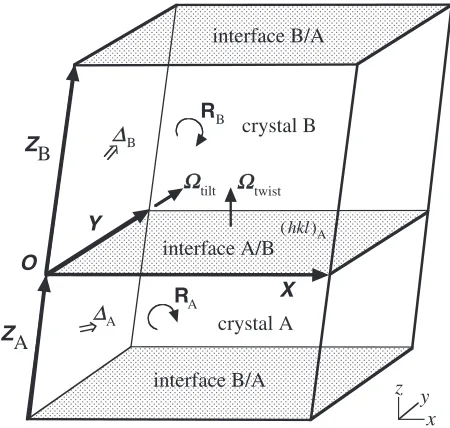
Let us consider a grain boundary model in a periodic parallelo-hexahedron cell (hereafter we call as MD cell) composed of two same, cubic single crystals A and B. The simplest geometry to satisfy three-dimensional periodicity is created by assuming the grain boundary being parallel to one face of MD cell, for exampleXY plane as shown in Fig. 1. Such a periodic model is constructed by finding appropriate rotation matricesRAandRBfor both crystals and translation vectors of MD cell X,Y andZ. Here we assume that two properties are designated for the model construction:value and Miller indices ðhklÞA which denote the interface orientation of crystal A at A/B boundary.
First we fix the vectors XandY. They are on the plane
ðhklÞAand should satisfy the periodicities of both crystals in different orientation. Solutions forXandY are found as the translation vectors in the array of CSL vectors on ðhklÞAas shown in Fig. 2. Primitive translation vectors of CSL in three-dimensions were given by Grimmer et al.4) up to ¼49. There are infinite number of solutions forXandY pairs. We can screen a few, useful pairs for the modeling Special Issue on Advances in Computational Materials Science and Engineering IV
which form, for example, a primitive cell of near rectangular shape or a smallest rectangular cell on the interface.
Translation vectors ZA and ZB for each crystals, on the other hand, does not need to be CSL vectors because the periodicity towardZis disconnected at boundaries. The only requirement is thatZAþZBis the translation vector of MD cell, or equivalently the vector between the same atoms in neighboring original and replica cells. It is useful to express ZAandZBas fractional multiples of a CSL vectorZwhich has outward orientation from the interface such asZ1orZ2in
Fig. 2. VectorsZA andZB can be expressed by usingZas nAZandnBZ, respectively, wherenAandnBare real numbers scaling the thicknesses of crystal layers. Further two proper-tiesAandBare needed to assign the translational shifts of two crystals from the origin. Three components of and
fractional part of nrelate to four microscopic freedoms for one interface. Two interfaces are microscopically identical if A¼B¼0and bothnAandnB are integers.
Rotation matrixRAexpressing the orientation of crystal A in model coordinate is determined so as to translateXandY vectors in crystal coordinate (Fig. 2) into model coordinate (Fig. 1). MatrixRBis expressed byRAR whereR is the
transformation operation for givenvalue. Primitive values of R is given by Grimmer et al.4) up to ¼49. If the
crystals belong to a point group other thanOh, an appropriate
operator for proper or improper rotation may be added to the primitive value.
2.2 Tilt and twist boundaries
It is useful to consider a series of boundary structures resulted by continuous rotation of crystals about a fixed axis. In this case, thevalue of boundary varies drastically with rotation angle, and near-random boundaries with very high values are frequently appears.5)In this section, we consider the modeling process of tilt and twist boundaries by the formulation using common rotation axisand rotation angle ! to supplement very high boundaries in simple geo-metries. This formalism is applicable to not only cubic but also non-cubic crystals.
Periodic models of tilt boundaries are created as follows. We assume that geometrical parameters are given in the forms of tilt,!, and interface orientation ðhklÞ0 with zero
tilting angle. Let us set the direction of tilt parallel to Y (Fig. 1). Next we calculate the lattice positions in model coordinate for zero tilting angle. Rotation matrix for zero tiltingR0is given so as to transformtiltandðhklÞ0in crystal
coordinate to those in model coordinate. Possible values for !satisfying the periodic condition is listed by founding a pair of lattice points in crystals A and B which move to the same positionXon the interface. Tilting angles of both crystals are expressed by !A¼tan1ðzA=xAÞ and !B¼tan1ðzB=xBÞ
wherexA,zA,xBandzB are the coordinates of lattice points with zero tilting. VectorXis given by (ðxA2þyA2þzA2Þ1=2,
yA, 0) and vectorY is chosen to be a lattice vector parallel to tilt. Rotation matrices RA and RB are expressed by Rð!AÞR0 and Rð!BÞR0, respectively, where Rð!Þ
repre-sent the rotation aboutY.
Vectors ZAandZB can be selected arbitrarily except for the requirement thatZAþZBmust be the translation vector of the MD cell. Microscopic identity of two interfaces is confirmed by assuming, for example,ZAandZBto be lattice vectors in tilted crystals andA¼B¼0. Shape of the MD cell is generally a parallelo-hexahedron. We can use a monoclinic cell in the case of symmetrical tilting with same crystal thicknesses, and even a rectangular cell ifyA¼0.
In the case of twist boundaries, we must consider two-dimensional periodicities on theXY plane for both crystals. Rigorous solutions which satisfy the periodicities are found only for limited number of twisting axistwist for example, cubic h100i, h110i and h111i, hexagonal h0001i, and tetragonal h001i. Twisting operation for each crystal is expressed by clockwise or anticlockwise rotation abouttwist perpendicular to the interface (Fig. 1). MatricesR0,RAand RB, vectorsXandY, and possible values of twisting angle! are evaluated in the same manner to the tilt boundary case.
x y z
crystal A
X Y
O
ZA
B
Z crystal B
interface B/A interface B/A
Ωtilt Ωtwist
RB
RA
∆A B
∆
interface A/B
(hkl)A
Fig. 1 Scematic diagram of two crystals, periodic grain boundary model. VectorsX,Y,ZAandZBare the translation vectors of two crystal cells. OriginOis placed on the interface A/B, and is referred by rotational and translation operations. Two interfaces A/B and B/A are paralell toxy plane. Orientation and translational shift of crystals A and B are denoted byRA,RB,AandB, respectively.
Z
1a
b
c
Y
1Y
2X
1X
2Z
2(
hkl
)
A
[image:2.595.55.280.72.286.2] [image:2.595.67.267.380.539.2]Selections ofZAandZB are arbitrary again, but are usually set to be perpendicular to the interface.
3. Software Implementation
Modeling procedures mentioned above have been imple-mented as separate menus in the present software. It consists of five menus namedcrystal,CSL,T/T(Tilt and Twist),edit
andsetas follows.
3.1 Crystal menu
At the beginning of modeling procedures, we must create a single crystal structure. Symmetry operations for 230 space groups are implemented in GBstudio. After assigning space group, lattice constants, elements and their asymmetric positions, single crystal structure is generated by pressing the ‘build’ button.
3.2 CSL menu
In this menu, we can construct various CSL boundary models up to¼99. This menu consists of a few selection lists and several input fields. Macroscopic parameters of boundary geometry are fixed by only two selections. First we choose onevalue in the selection list. GBstudio has a list of 146values up to¼99. Second we select desired Miller indices for interface planes. In GBstudio, candidates of interface orientation were registered for each value according to the density of simple cubic coincident site on the interface. It is known that interfaces with high coincident site density is energetically favorable and frequently found in existing materials.5,7–9) More than 1000 orientation of the interface are registered in GBstudio. In case of ¼3, for example, 29 different interface orientation can be chosen in the primitive rotation space. Choice of interface orientation is extended by selecting non-primitive rotation as mentioned below. After fixing the macroscopic parameters of the boundary, translation vectors of MD cell X, Y and Z can be chosen in the candidate lists. After the selection, we construct a desired periodic CSL model in unit MD cell by pressing the ‘build’ button. Stacking of the fundamental periodic cell towardXandY, and also the crystal thicknesses toward Z can be modified in the respective input fields. Microscopic parameters of boundary geometry can be assigned by fraction numbers of crystal thicknesses and ‘crystal shifts.’
GBstudio assumes the primitive values of misorientation ofOhsymmetry for assingedvalue. Misorientation out of
the primitive rotation space can be assigned by the selection list ‘rotational variants.’ Necessary operators for proper or improper rotation are implemented in the list which are selectable for crystal A and B independently. This operation is applicable not only cubic crystals but also hypothetical crystals in a cubic unit cell with lower symmetries.
If the resulted model is unsatisfactory due to the close pairs at the interface, we can proceed to theeditmenu mentioned below to modify the atomic arrangements at the interface.
3.3 T/T (Tilt and Twist) menu
Operations for tilt and twist boundaries are implemented here. These boundaries can be modeled again by using a few
selection lists and input fields. First we select a boundary type between tilt and twist. Next we select the rotation axis and interface at zero rotation among the registered Miller indices. Rotation angles which satisfy the periodic condition can be assigned in two ways, selection among the candidates, or selecting two integers corresponding to lattice coordinates. Selection lists for rotational variants are also implemented in this menu and are useful for generating twin boundaries. Optional input field for grain boundary spacing is added in order to avoid an array of close atomic pairs which is frequently generated in low angle tilt boundaries.
3.4 Edit menu
This menu is implemented so as to modify unfavorable atomic arrangements at the boundary. We can list up such unfavorable atomic pairs of which bond lengths are shorter than a specified value by the ‘search’ button. Listed atomic pairs can be modified individually by ‘elimination’ and ‘merge’ options. The modified model can be stacked toward XandYby the ‘stack’ button. This option is useful when we construct a large model as the repetition of a smaller modified model.
3.5 Set menu
In this menu we can change the default settings on atomic colors, radii, axes choice, output format and other properties.
Above mentioned menus and three-dimensional drawings of the model were coded by Java language. Two different versions of GBstudio were developed based on different graphics environments, plane Java and Java 3D. The plain Java version can deal with a large model consists of about one million atoms. The Java 3D version is superior in graphics drawing but the maximum size of the model is limited to about 10000 atoms.
Sample data of single crystals and grain boundary models can be recalled by the ‘open’ button. Atomic coordinates in the constructed models can be saved by using the ‘browse’ and ‘save’ buttons. The ‘save’ button works only in the GBstudio application version and is disabled in the applet version due to the security reason on local systems. In the case of the GBstudio applet version, which is distributed via the Internet6) for use on web browsers, atomic coordinates can be incorporated to a local file by copying the data in pop-up window shown by the ‘browse’ button.
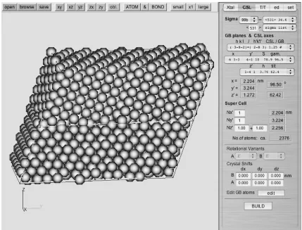
As an example of model construction, a screenshot of GBstudio building fcc99b,h531i34.6, {2883} boundary is
shown in Fig. 3. This model consists of399cubic cells in each crystal layer, hence 2376 atoms in a parallelo-hexahedron MD cell. Only four selections were required to build this model after constructing the single crystal.
4. Discussion
values and several representative interface geometries. Recent improvement on experimental technique by electron backscattered diffraction reveals the distribution of not only the misorientation but also the orientation of individual interface. Sayleret al.7,8)measured five macroscopic param-eters of individual grain boundary in magnesia polycrystals and found preference choices on boundary orientation. GBstudio is useful for investigating such orientation depend-encies by systematic molecular simulation.
Five macroscopic parameters of grain boundary are usually expressed by misorientation and boundary orienta-tion. In GBstudio, macroscopic parameters are assigned by the properties in materials science such asvalue and Miller indices. These properties are probably familiar to the users compared with mathematical variables such as Euler angles. Selectable items are registered in the selection lists, hence we can assign the boundary geometry very easily.
The most important merit of GBstudio is the applicability to periodic boundary conditions. If the boundary model is non-periodic, surfaces surrounding the model cause a severe effect on the simulation result and may mask the effect of the interface. There are a lot of software for generating atomic coordinates of crystal structures, and some of them insist on their applicability to boundary models by connecting two crystal slabs. In such software, however, input parameters for a desired boundary must be assigned by users. It is not easy to find appropriate values for a periodic model of specified boundary, especially for highor asymmetric boundaries.
Microscopic parameters on boundary structures are also
considered in GBstudio. They are assigned by the fractional parts of crystal thicknesses and translational shifts of two crystals. Such microscopic freedoms frequently bring artifi-cial atomic arrangements in the resulted boundary model. GBstudio can modify such unfavorable structures by manip-ulating close atomic pairs individually. It should be noted that, however, such a modified model is still a candidate for actual grain boundary structures and should be confirmed by experiments or theoretical calculation.9) We must pay attention to the microscopic structures of not only the first interface but also the second one, and also to their identity. In GBstudio, microscopic parameters of two interfaces can be handled independently, and hence their identity is easily attained.
5. Conclusion
A new builder software GBstudio was developed for generating atomic coordinates in periodic grain boundary models. CSL boundaries up to99and representative tilt and twist bondaries can be easily constructed by selecting a few parameters in the candidate lists. It is useful for systematic studies on grain boundary properties by molecular simula-tion.
Acknowledgement
[image:4.595.83.512.71.398.2]source codes. This study was supported by the TACC project ‘Development of general purpose molecular dynamics code for large scale systems (TACPACK)’ in AIST. GBstudio was developed as a module of TACPACK.
REFERENCES
1) D. Raabe:Computational materials science, (Wiley-VCH, Weinheim, 1998), and references on pp. 104–106.
2) A. P. Sutton and R. W. Balluffi: Interfaces in crystalline materials,
(Oxford University Press, Oxford, 1995).
3) W. Bollmann: Crystal defects and crystalline interfaces, (Springer-Verlag, Heidelberg, 1970).
4) H. Grimmer, W. Bollmann and D. H. Warrington: Acta Cryst. A30
(1974) 197–207.
5) For example, D. Wolf: Phil. Mag. A62(1990) 447–464. 6) H. Ogawa:http://staff.aist.go.jp/h.ogawa/GBstudio/(2003).
7) D. M. Saylor, A. Morawiec and G. S. Rohrer: Acta Mater.51(2003) 3663–3674.
8) D. M. Saylor, A. Morawiec and G. S. Rohrer: Acta Mater.55(2003) 3675–3686.