Observer based Dynamic Adaptive Cooling System for
Power modules
Xiang Wang, Alberto Castellazzi, Pericle Zanchetta
The Power Electronics, Machines and Control (PEMC) Research Group, Electrical Systems and Optics Research Division, Department of Electrical and Electronic Engineering, University of Nottingham, Nottingham, NG7 2RD, United Kingdom (UK).
Abstract
This paper presents an advanced dynamic cooling strategy for multi-layer
structured power electronic modules. A observer based feedback controller
is proposed to reduce a power device or module’s thermal cycle amplitude
during operation, with the aim of improving reliability and lifetime. The
full-state observer design is based on a developed Cauer type thermal model.
The observer enables estimation and control of the temperature at reliability
critical locations only measuring one accessible location. This makes the
method particularly powerful and suitable for application in power systems.
The designed strategy is confirmed experimentally. Although the experiment
is developed for a specific application scenario, the proposed strategy is of
general validity.
Keywords: Cooling, Reliability, Temperature Control, Thermal Stress,
Thermal Cycle, Lifetime
Email addresses: [email protected](Xiang Wang),
[email protected](Alberto Castellazzi),
1. Introduction
In power electronics, the failure mechanisms generally can be grouped by
random and wear-out failures [1, 2, 3]. Wear-out mechanism failures make
up the majority of failures in power electronic modules [4]. In wear-out
mechanism, thermo-mechanical stress plays a very important role in
affect-ing power electronic devices/modules reliability [1, 5], such as the fractures
propagation and degradations in solder layers [6], wire-bond lift-off [7] and
emitter metallization [8]. The failure mechanisms are influenced by both
en-vironmental and load conditions [9, 10]. To address this issue, research has
addressed different aspects, for example, new semiconductor and materials
technologies [11, 12], package architecture [13], interconnection [14], control
of power electronic modules [15] and advanced cooling technologies [5, 16].
Fig. 1 describes a summary of the results of extensive reliability tests
on IGBT power modules [17]. These results clearly indicated that, over the
considered temperature range, a power module operational lifetime depends
mainly on two parameters: 1) the amplitude of the thermal cycles, ∆T, that
the module experiences; 2) the average operational temperature, Tm. Fig. 1
clearly shows that if ∆T is reduced by even the same amount that Tm is
increased, a much higher number of cycles to failure can be achieved. For
instance, moving from point 1 to point 2, as ∆T is fixed at 50K, increasing
Tm by 20K from 80◦C (353.15K) to 100◦C (373.15K), the cycles to failure
will be reduced 3×10⁵ cycles from point 1 (5×10⁵ cycles) to point 2 (2×10⁵
cycles). However, moving from point 2 to point 3, keeping the same Tm, a
reduction of 20K in ∆T increases the number of cycles to failure to 2×10⁶,
∆T has a much more significant effect on the reliability of power modules
[image:3.595.147.463.196.371.2]than Tm.
Figure 1: Reliability of power modules as a function of thermal cycle amplitude for different values of average temperature [17]
Presently, typical power device thermal management only aims at
ensur-ing that the maximum operatensur-ing temperature is kept below a safety critical
value at full-load or worst-case conditions and the cooling device is based
on fixed designed parameters. In view of the close considerations, from a
reliability point of view, this is clearly not optimum. Some temperature
regulated thermal management strategies have been proposed with
consider-ation of maintaining device operconsider-ation temperature variconsider-ation as small as
pos-sible [18, 19, 20]. A temperature control system is presented in [18], where the
device under test (DUT) is sandwiched with a heat sink and heater. By
elec-trically controlling the heater power, heat flow to/from the electronic device
is quickly adjusted; and that in turn regulates the device temperature. This
costs extra power for heating the device to a certain temperature value. The
patent in [19] demonstrates a temperature controlled cooling method. In this
method, the DUT is cooled by mechanically swing the cooling fluid direction
(e.g. the cooling fan facing direction) towards the heat dissipation element
to regulate the temperature to a target value. However, this method requires
several parallel mounted cooling fans and each fan needs a motor for swing
functions, which increases the complexity of the cooling system and limits
its thermal response time. In [20], a method to control the fan speed used in
cooling integrated circuits is presented. In this method, a thermal diode is
used to monitor device temperature, and the fan speed is adjusted by looking
up a pre-defined temperature-speed table. There are two main shortages for
this method: 1) a temperature sensor must be mounted inside the device; 2)
controlling cooling fan by look-up table is an open loop control thus it is
sen-sitive to system variations and easy to have temperature errors. Therefore,
considering the reliability and temperature control issues, an observer-based
adaptive cooling strategy with multi-variable feedback control technique is
proposed here.
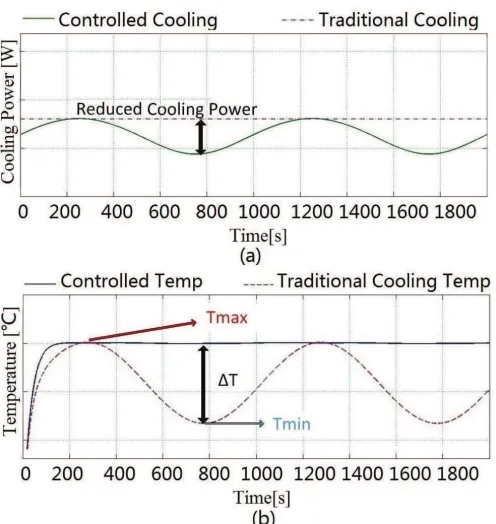
As shown in Fig. 2, the temperature with constant cooling power will
vary as load changes. In order to decrease ∆T, the cooling power can be
adjusted according to the load variations and this can be achieved simply by
Figure 2: Change in thermal cycling with traditional cooling approach and with the pro-posed cooling strategy: (a) Cooling power (b) Temperature
This paper presents an advanced dynamic cooling strategy for multi-layer
structured power electronic modules. An observer based feedback controller
is proposed to reduce a power device or module’s thermal cycle amplitude
during operation, with the aim of improving reliability and lifetime. The
proposed methodology is schematically illustrated in Fig. 3:
Controller Zth
∑ ∑
-+ + +
Tref Terr VCooling DT Tout
Tamb
Pdiss
[image:5.595.168.447.556.646.2]the temperature at a reliability critical location of the power assembly is
controlled against variations in the actual load and power losses Pdiss (i.e.,
power dissipation) and boundary conditionTamb (i.e., ambient temperature).
The feedback control loop monitors the temperature of the desired location
Tout and intervenes on the cooling parameter Vcooling to eliminate
tempera-ture errorsTerr to control the temperature output and decrease temperature
variations. The control parameter Vcooling is the controller output signal used
to control the cooling devices. It can be the bias voltage applied on the fan
for a forced air convection cooling, or the voltage on the pump in a liquid
cooling system. By controlling the cooling device, the thermal impedance of
the system, Zth, is adjusted to meet the temperature regulation. A observer
based feedback controller is proposed to reduce a power device or modules
thermal cycle amplitude during operation, with the aim of improving
reli-ability and lifetime. The full-state observer design is based on a developed
Cauer type thermal model. To ensure the accuracy of the developed model,
FEA (Finite Element Analysis) method is applied to deriving a Cauer type
thermal network where the observer is modelled on. The observer enables
estimation and control of the temperature at reliability critical locations only
measuring one accessible location. This makes the method particularly
pow-erful and suitable for application in power systems. The designed strategy is
confirmed experimentally. Although the case-study experiment is developed
2. Temperature Estimation
A common way to estimate junction temperature is building a real-time
thermal model and match the model to experiment data to get a reference
look-up table for temperature estimation [21]. This requires high accuracy
physical parameters, proper initial conditions to ensure the precision of
mod-elling, high initial efforts to build up the look-up table and basically only for
junction temperature estimation. Here, the proposed temperature full-order
observer is a system that provides an estimation of the internal states
(tem-peratures) of a given real system (power module). The state-space thermal
model is based on module’s physical structure and material properties, thus
with knowing the system’s inputs Pdiss (i.e., power dissipation), Tamb (i.e.,
ambient temperature) and output (i.e., the temperature at any certain layer
location inside the module), the observer will be able to calculate the junction
temperature and temperatures at other layers inside the module. This
en-ables that many modules have inbuilt temperature sensors [22] can be used
with the proposed observing method. The system states are necessary to
solve many control theory problems so that the state observer can be used
in investigating the critical temperature location (e.g. junction temperature
or solder layer temperature) in active temperature control applications.
Be-cause the temperatures are treated as internal states in the observer, the
temperature information at all physical layers can be achieved at same time.
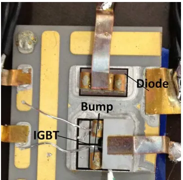
For validation purposes a simple test assembly was produced as shown in
Fig. 4, and the validation process and results are discussed in detail in early
works [23]. This consists of an IGBT to be used as the heating element and a
terminal) was contacted with hollow copper bumps, into which a
thermocou-ple (here, a K-type thermocouthermocou-ple was used) was inserted to provide a second
temperature measurement point, much closer to the actual heat source (i.e.,
the IGBT chip). The IGBT is driven in the on-state with a constant
gate-emitter voltage; a variable DC voltage source is connected to collector and
emitter to generate variable power dissipation; the diode, previously duly
calibrated, is biased with constant current (500mA) to monitor variations of
[image:8.595.212.395.324.504.2]its forward voltage drop with temperature.
Figure 4: Tested IGBT assembly
The Cauer type thermal network is built because it can represent a real
physical heat-flow path. To ensure the accuracy of the thermal model, the
thermal resistance and thermal capacitance values inCauer network are
de-rived from FEA simulation results [24]. The test model is built in 3-D with
FEA software, Abaqus. In FEA simulation, assuming a 100W power is
source. Adiabatic boundary conditions are applied to the top and lateral
sur-faces and convective boundary conditions are applied to the bottom surface
only (heat-sink). As mentioned above, for most cooling conditions and
as-sembly structures, heat conduction can be assumed to take place essentially
in the vertical direction, from the chips towards the heat-sink, enabling for
an essentially 1-D treatment of the problem. This allows derivation of the
associated thermal resistance Ri, and thermal capacitance,Ci, of each layer.
Therefore, the temperature measuring locations are set to the elements
be-neath the centre of the IGBT gate chip, and in the center of each material
layer. To verify the extracted parameters, a Cauer type thermal model is
simulated in Simulink with the same load parameters in Abaqus, and the
simulated temperature results are compared with the original FEA results.
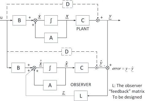
Based on the derivedCauernetwork, the thermal model can be formalised
in the framework of state-space description. Based on this state-space model,
a full-order state observer can be built in the form of Fig. 5 [23]:
B ∫ A C D u + + + PLANT B ∫ A C D + + + OBSERVER L +
-L: The observer
[image:9.595.183.419.478.643.2]“feedback” matrix. To be designed
3. Temperature Control System Design
Based on the proposed thermal modelling method and the temperature
observer, the adaptive cooling system controller can be designed. Usually, the
equations of the thermal model involving the controllable thermal impedance
Zth (or using thermal resistance Rcooling for simplicity) and the cooling
pa-rameter Vcooling are non-linear. However, modern control system design is
mainly based on linear system design: analysis methods are much easier for
linear models than for non-linear models. Therefore, the developed
ther-mal model must be linearised so to allow control methods to be applied and
achieve the expected thermal performance.
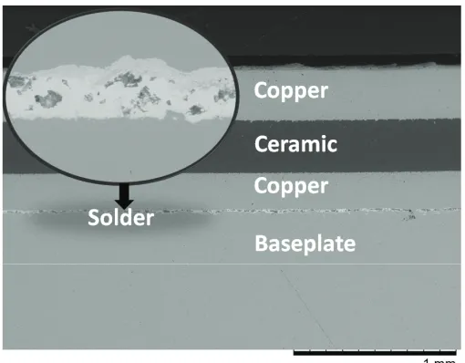
The thermal system used in the experiment is modelled based on an
Cauer-type electrical equivalent circuit for the assembly including the
cool-ing device. In the circuit structure shown in Fig. 6, each node of the network
corresponds to an actual physical location of the assembly: voltage
[image:10.595.159.451.483.600.2]corre-sponds to temperature and current to heat-flow.
Figure 6: Thermal-Electrical equivalent circuit of a typical assembly
Here, the convective boundary conditions are emulated by means of a
well as the convection part. The action of the convection cooling is modelled
by Equation (1), where the cooler’s thermal resistance, Rcooling, is a function
of control parameters (e.g., the bias voltage of a fan or that of a liquid cooler’s
pump). Here, Rcooling becomes the control variable and it will be adjusted
during the operation.
Φ = Tn−Tamb
Rn+Rcooling (1)
Based on the derived equivalent thermal model, the state-space model
used for the temperature controller design can be built, and the detailed
pro-cedure is described in [25, 26] . Note that due to the non-linearity of Rcooling
and Vcooling, the state-space system must be linearised before designing
con-troller with it.
In the state-space system, among the inputs, only Vcooling is the
control-lable signal, and both Pdiss and Tamb are decided by the loading and the
external environment so that they can be treated as system disturbances.
To control the output temperature at the desired value accurately, the
sys-tem output sys-temperature must present zero steady-state error to a step
com-mand. However, using the multivariable state feedback control on its own,
any change in the model parameters will cause the error to be non-zero.
Therefore, integral control is introduced. Then, the open-loop system
eigen-values (poles) of the augmented system can be calculated and the closed-loop
poles can be placed according to the desired dynamic response performance
by the feedback law. A detailed feedback controller design and validation on
4. Reliability Testing: Proof of Concept Demonstration
A photograph of the test vehicle is shown in Fig. 8: it is a commercial
[image:12.595.140.466.204.372.2]IGBT module mounted on a fanned heat-sink.
Figure 7: Tested IGBT module on heat-sink
It was subjected to 3000 temperature and power cycles derived from a
realistic mission profile for wind applications, shown in Fig. 8. The
tem-perature at baseplate was measured during operation, a certain part of two
cycles is shown in Fig. 9. With the collected baseplate temperature and the
proposed observer, the reference temperature at the solder layer beneath the
substrate is set to 80 ◦C, which is the peak solder layer temperature with
fixed cooling. However, during the steady state, the thermal chamber used
in this experiment shifts its temperature somewhat so that the temperature
with fixed cooling shifts as well. But, the controlled one can still reach its
reference temperature by adjusting its cooling power, therefore a peak
tem-perature difference Tdif f is generated as shown in Fig. 9. From the measured
cannot keep temperature constant during the whole cycling due to the harsh
ambient temperature change, it still can reduce almost 45◦C in ∆T with only
increasing 20◦C in its average temperature. This 25◦C temperature difference
can improve the device reliability a lot.
0 500 1000 1500 2000
-20 -10 0 10 20 30 40 50 60 70 Time (s) T e m p e ra tu re ( C ) / C u rr e n t (A )
Programmed current (A)
[image:13.595.180.427.222.401.2]Ambient temperature (C)
Figure 8: Long-term degradation test conditions for active and passive thermal cycling
Tdiff
∆T=20C
∆T=65C
[image:13.595.180.423.447.624.2]The proofs of reliability and lifetime improvement are demonstrated by
checking the tested IGBT module solder layers, which are scanned before and
after the test for both of the adaptive cooling and fixed cooling solutions. The
SAM (Scanning Acoustic Microscope) scanned pictures are shown in Fig. 10
[image:14.595.177.431.259.459.2]and Fig. 11.
Figure 10: Fixed cooling: Tested IGBT module baseplate solder layer SAM scan results after 3000 temperature cycles.
Fig. 10 shows the tested IGBT module baseplate solder layer SAM scan
results with fixed traditional cooling strategy after 3000 temperature cycles:
the comparison of results before and after the test shows that degradation
and solder delamination happened around the solder layer corner first under
Figure 11: Adaptive controlled cooling: Tested IGBT module baseplate solder layer SAM scan results after 3000 temperature cycles.
Fig. 11 shows the tested solder layer SAM scan results with the proposed
adaptive cooling strategy after 3000 temperature cycles: the comparison of
results before and after the test shows that by regulating the temperature
variation amplitude during cycling, there is no obvious degradation. These
results prove that the proposed adaptive cooling improves solder layer
relia-bility , as indicated in the red area along the edge side.
To have a more detailed observation of the tested device, cross-section
examination of the devices near solder layer edge (the location as the yellow
dashed lines in Fig. 10) are scanned by SEM (Scanning Electron Microscope),
Figure 12: SEM cross-section scanning for fixed cooling solution
In the case of traditional fixed cooling, shown in Fig. 12, the baseplate
solder layer has cracks and voids generated by the cycling test and the solder
layer becomes thinner along its edge due to the warpage of the device during
Figure 13: SEM cross-section scanning for adaptive cooling solution
In the case of adaptive cooling, shown in Fig. 13, due to the controller
reduces the ∆T so that the thermal-mechanical stress is reduced, there is
no obvious void or crack is observed, and the solder layer thickness is kept
as its original value. By comparing Fig. 12 and Fig. 13, it can be observed
that the copper-ceramic interface in the substrate becomes more rough in
fixed cooling than adaptive cooling. A compare of more zoomed-in scanning
Figure 14: SEM cross-section scanning on substrate for fixed cooling solution
In Fig. 14, it can be seen that the thermal cycling test develops coarse
ceramic grains in substrate when fixed cooling strategy is applied.
Figure 15: SEM cross-section scanning on substrate for adaptive cooling solution
[image:18.595.177.430.419.616.2]are still smoothly arranged and the copper-ceramic interface is much more
smooth than the fixed cooling one. Therefore, it can be summarised that the
module with adaptive cooling solution has better performance in preventing
voids generation and cracks propagation in solder layer, and even reduce
copper-ceramic thermal-mechanical stress. The results clearly show that the
proposed adaptive cooling can improve solder layer reliability and elongate
device lifetime.
5. Conclusion
In this paper, an observer based dynamic adaptive cooling strategy has
been proposed and validated. Considering the effect of temperature variation
∆T and average temperature Tm on device reliability, the proposed cooling
strategy uses multi-variable feedback control to regulate the device
tempera-ture against loads variations (e.g. power and ambient temperatempera-ture change).
With the developed feedback controller, a higher temperature reduction in
∆T is achieved than the increase in Tm. This regulated temperature result
leads to an extended device lifetime. It can be observed from the
experi-mental results that the proposed dynamic cooling strategy improves device
lifetime beyond the existing fixed cooling method by adaptively adjust its
cooling power to the loads. Due to the cooling power being controlled within
its maximum value, the adaptive cooler does not require more power than
the traditional fixed cooling.
Another original contribution of this work is the use of a temperature
desired locations inside a commercialised module during operation, a
tem-perature observer is proposed and validated. The proposed observer is able
to estimate the internal module temperature (e.g. junction temperature or
solder-layer temperature) in real-time without opening its package by just
measuring the temperature at one accessible location (e.g. baseplate, heat
sink). As the temperature dynamics information is reflected by the power
dissipation and the ambient temperature signals, the observer doesn’t rely on
the dynamics of the temperature sensor. Therefore, the observer is especially
suitable for power electronics temperature monitoring applications.
To verify the proposed cooling strategy, the observer and feedback
con-troller were validated separately and then tested combined together on a
commercial IGBT module (case-study). The test condition are scaled from
domestic wind-turbine inverter applications, but the idea is very general and
can be applied to a broad variety of power electronics applications (e.g.
au-tomotive, ship). During this case-study implementation, the power and
tem-perature cycling were ran simultaneously for 3000 cycles. Temtem-perature at the
IGBT baseplate were compared and a reduction of 45◦C in ∆T is achieved.
The solder layer degradation were compared between the proposed
adap-tive cooling and the fixed cooling method by SAM and SEM scanning. The
results demonstrate good result in improving device reliability and lifetime
References
[1] M. Ciappa, Selected failure mechanisms of modern power modules,
Microelectronics Reliability 42 (2002) 653 – 667.
[2] T. Nakagawa, Replacement policies for a unit with random and wearout
failures, Reliability, IEEE Transactions on R-29 (1980) 342 –344.
[3] D. Badenius, Random failure, Reliability, IEEE Transactions on R-19
(1970) 86 –88.
[4] X. Li, J. Qin, J. Bernstein, Compact modeling of mosfet wearout
mecha-nisms for circuit-reliability simulation, Device and Materials Reliability,
IEEE Transactions on 8 (2008) 98 –121.
[5] X. Wang, A. Castellazzi, P. Zanchetta, Regulated cooling for reduced
thermal cycling of power devices, in: Power Electronics and Motion
Control Conference (IPEMC), 2012 7th International, volume 1, pp.
238 –244.
[6] M. Bouarroudj, Z. Khatir, J. Ousten, F. Badel, L. Dupont, S. Lefebvre,
Degradation behavior of 600v–200a igbt modules under power cycling
and high temperature environment conditions, Microelectronics
Relia-bility 47 (2007) 1719–1724.
[7] B. Ji, V. Pickert, B. Zahawi, M. Zhang, In-situ bond wire health
moni-toring circuit for igbt power modules, in: Power Electronics, Machines
and Drives (PEMD 2012), 6th IET International Conference on, pp. 1
[8] V. Smet, F. Forest, J. Huselstein, F. Richardeau, Z. Khatir, S.
Lefeb-vre, M. Berkani, Ageing and failure modes of igbt modules in
high-temperature power cycling, Industrial Electronics, IEEE Transactions
on 58 (2011) 4931 –4941.
[9] X. Perpina, J.-F. Serviere, J. Urresti-Ibanez, I. Cortes, X. Jorda, S.
Hi-dalgo, J. Rebollo, M. Mermet-Guyennet, Analysis of clamped inductive
turnoff failure in railway traction igbt power modules under overload
conditions, Industrial Electronics, IEEE Transactions on 58 (2011) 2706
–2714.
[10] G. Buiatti, J. Martin-Ramos, C. Garcia, A. Amaral, A. Cardoso, An
online and noninvasive technique for the condition monitoring of
ca-pacitors in boost converters, Instrumentation and Measurement, IEEE
Transactions on 59 (2010) 2134 –2143.
[11] L. Ngwendson, M. Sweet, E. Narayanan, An overview of the recent
de-velopments in high-voltage power semiconductor mos-controlled bipolar
devices, in: Bipolar/BiCMOS Circuits and Technology Meeting, 2009.
BCTM 2009. IEEE, pp. 198 –205.
[12] A. Morozumi, K. Yamada, T. Miyasaka, S. Sumi, Y. Seki,
Reliabil-ity of power cycling for igbt power semiconductor modules, Industry
Applications, IEEE Transactions on 39 (2003) 665 – 671.
[13] S. Igarashi, H. Kakiki, Y. Nishimura, T. Goto, Design of high
reliabil-ity packaging for fuji high power module, in: Electrical Machines and
[14] U. Scheuermann, Reliability challenges of automotive power electronics,
Microelectronics Reliability 49 (2009) 1319 – 1325.
[15] D. Murdock, J. Torres, J. Connors, R. Lorenz, Active thermal control
of power electronic modules, Industry Applications, IEEE Transactions
on 42 (2006) 552–558.
[16] Skuriat, Robert and Johnson, C. M., Direct substrate cooling of power
electronics, Integrated Power Systems (CIPS), 2008 5th International
Conference on (2008) 1 –5.
[17] U. Scheuermann, U. Hecht, Power cycling lifetime of advanced power
modules for different temperature swings, PCIM Nuremberg (2002)
5964.
[18] Babcock, James Wittman and Tustaniwskyj, Jerry Ihor, Temperature
control system for an electronic device in which device temperature is
estimated from heater temperature and heat sink temperature, 1998. US
Patent 5,844,208.
[19] W. J. Anderl, C. M. Huettner, Real time adaptive active fluid flow
cooling, 2010. US Patent 7,733,649.
[20] D. K. Singh, F. I. Atallah, D. H. Allen, Fan speed control from adaptive
voltage supply, 2013. US Patent 8,515,590.
[21] M. Musallam, C. M. Johnson, Real-time compact thermal models
for health management of power electronics, Power Electronics, IEEE
[22] Schuh, William C, Smart temperature sensing device, 1999. US Patent
5,857,777.
[23] X. Wang, A. Castellazzi, P. Zanchetta, Full-order observer based
igbt temperature online estimation, in: Industrial Electronics Society,
IECON 2014-40th Annual Conference of the IEEE, IEEE, pp. 1494–
1498.
[24] C.-S. Yun, P. Regli, J. Waldmeyer, W. Fichtner, Static and dynamic
thermal characteristics of igbt power modules, in: Power Semiconductor
Devices and ICs, 1999. ISPSD’99. Proceedings., The 11th International
Symposium on, IEEE, pp. 37–40.
[25] X. Wang, A. Castellazzi, P. Zanchetta, Observer based temperature
control for reduced thermal cycling in power electronic cooling, Applied
Thermal Engineering 64 (2014) 10–18.
[26] X. Wang, Y. Wang, A. Castellazzi, Reduced active and passive thermal
cycling degradation by dynamic active cooling of power modules, in:
Power Semiconductor Devices & IC’s (ISPSD), 2015 IEEE 27th
Inter-national Symposium on, IEEE, pp. 309–312.
[27] Khapugin, AA and Martynenko, VA and Nischev, KN and Novopoltsev,
MI, Calculation of stress-deformation states in power semiconductor
![Figure 1: Reliability of power modules as a function of thermal cycle amplitude for differentvalues of average temperature [17]](https://thumb-us.123doks.com/thumbv2/123dok_us/8662661.375463/3.595.147.463.196.371/figure-reliability-modules-function-thermal-amplitude-dierentvalues-temperature.webp)