UNDERSTANDING CREATIVE DESIGN PROCESSES BY INTEGRATING
SKETCHING AND CAD MODELLING DESIGN ENVIRONMENTS
A Preliminary Protocol Result from Architectural Designers
Yi Teng Shih1*, William D. Sher2, and Mark Taylor2
1The University of Nottingham, Ningbo, China 2The University of Newcastle, Newcastle, Australia
*Corresponding Author’s email address: Yi-teng.shih@nottingham.edu.cn
Abstract
This paper presents the results of a preliminary protocol study of the cognitive behaviour of architectural designers during the design process. The aim is to better understand the similarities and differences in cognitive behaviour using Sequential Mixed Media (SMM) and Alternative Mixed Media (AMM) approaches, and how switching between media may impact on design processes. Two participants with at least one-year’s professional design experience and a Bachelor of Design degree, and competence in both sketching and computer-aid design (CAD) modelling participated in the study. Video recordings of participants working on different projects were coded using the Function-Behaviour-Structure (FBS) coding scheme. Participants were also interviewed and their explanations about their switching behaviours were categorised into three types: S→C, S/C↹R and C→S. Preliminary results indicate that switching between media may influence how designers identify problems and develop solutions. In particular, two design issues were identified. These relate to the FBS coding scheme, where structure (S) and behaviour derived from structure (Bs), change to documentation (D) after switching from sketching to CAD modelling (S→C). These switches make it possible for designers to integrate both approaches into one design medium and facilitate their design processes in AMM design environments.
Keywords: Creative design process, sketching, CAD modelling, cognitive behaviour, mixed media design environments.
INTRODUCTION
comprehensive understanding of cognitive behaviour in AMM design environments. Questions about the differences between SMM and AMM and whether switching between media impacts on the design process remain unanswered and are therefore important to explore.
To address these questions, a protocol study was conducted in which two professional architectural designers were asked to perform an architectural design task in SMM and AMM design environments. Protocol analysis and the Function-Behaviour-Structure (FBS) coding scheme were adopted and developed as the research method to analyse participants’ cognitive behaviours. Preliminary results identify the cognitive changes that differentiate SMM from AMM as well as the impact of switches in design processes. These are discussed in this paper.
RELATED DESIGN STUDIES
Providing solutions that effectively meet the requirements of design briefs is the ultimate goal of designers. A creative design process is best defined by its output - creative design processes produce great design outcomes (Sobek II and Jain, 2004). Teaching students about creative design processes is a common goal of many architectural design courses worldwide. The earliest phase of the design process focuses on understanding the problem at hand and making decisions about solutions (Cross and Dorst, 1999). This phase, referred to as conceptual design, has a significant impact on detailed design, cost and construction. Some methodological studies about this phase, such as the synectics method (Gordon, 1961) and the brainstorming method (Osborn, 1963), highlight the importance of sketching or drawing to illustrate concepts. Sketching has been intensively studied in early architectural design, where individual designers begin to develop their conceptual designs for a building by sketching a plan, elevation, or a view of a building (Eckert et al., 2010) or by making unexpected discoveries about design problems (Suwa et al., 2000).
Research on sketching design environments
Sketching is used not only to communicate the results of architectural design to clients, users, legislators and constructors, but also as a central tool in the design process (Lawson, 2002). Sketching plays a pivotal role in the initiation and development of creative ideas during the early design phase. Designers rely on it to support and accentuate the visual reasoning necessary to explore the spatial relationships between diagrams. The design problem space evolves from an ill-defined problem to the identification and resolution of creative ideas when designers interact with sketches.
Sketching makes an important contribution to the design process. Initially designers brainstorm as many ideas as possible. Sketching is central to this process as raw sketches can be easily generated, revised, refined and consolidated as ideas are developed. Consequently, sketches act as a conceptual tool for designers, supporting and stimulating creative ideas (Goldschmidt et al., 1992). Suwa and Tversky (2001) argue that professional designers use sketching to generate new ideas, rather than to simply express current ideas. They observe that the simple process of re-examining old sketches, including one’s own and others’ can lead to unexpected discoveries that generate new ideas.
Research on CAD design environments
The expressive and geometric power of CAD modelling has increased to such an extent that it can be used by itself from beginning to end to achieve design goals. This approach replaces traditional methods such as sketching and can be termed a digital design process. Although traditional sketching methods are low cost, 2D representations may not convey ideas about complex 3D objects. For example, sketches are imprecise when multiple 2D views are used to produce a 3D perspective. In a CAD modelling design environment, 3D graphics (e.g. perspective views) can be employed to generate and manipulate 3D geometry (Aish, 1986). CAD modelling can be meaningfully used to support problem-solving in the design process. Conventional approaches involve sketching as a means of representing basic conventions, but these are inadequate for solving complex problems (Lin, 2001).
More recently, CAD modelling has proved to be effective across the whole range of AEC practices. Designers and clients use CAD models to review and evaluate building designs before construction. This provides them with opportunities to make substantial changes at a reasonable cost. Engineers use CAD models to evaluate structural alternatives (Reffat, 2002). Industry professionals use CAD models to estimate costs and to plan for cost-effective construction sequences. These processes frequently unearth design conflicts that would otherwise result in expensive construction defects. For existing buildings it is often desirable to use CAD models to analyse energy properties, to explore how a potential fire could spread, to explore potential changes in a building, and to increase the possible uses of existing building spaces (Lewis and Sequin, 1998). Some argue that cost savings of at least 30% are possible if the design and construction industry commits itself to complete CAD modelling (BSS, 1997). Moreover, the accurate visualisations possible with CAD modeling may help designers to alter and refine their design thinking (Salman et al., 2014).
There are thus clear advantages to using CAD to support design processes, and researchers continue to seek ways to integrate sketching and CAD modelling into one design medium to improve the conceptual design phase.
Research on mixed media design environments
In recent years research has shifted from single design mediums to the influence of mixed media on cognitive activities during the conceptual design phase. Evidence for the use of mixed media comes from Sachse et al. (2001) who surveyed more than 100 expert designers who used sketching prior to and concurrently with CAD modelling. Their study identified three positive outcomes of this approach: better solutions, faster task completion, and fewer processing steps to develop CAD models. These results are supported by Chen (2007) who studied design creativity by using conventional and digital media simultaneously. The results showed that as designers switch from sketching to digital tools, design creativity is stimulated because switching behaviour causes designers to re-think previous ideas and to improve the quality of their designs.
Ibrahim and Rahimian (2011) argued that the CAD software available at the time did not facilitate the intuitive aspects of conceptual design. Therefore they introduced the concept of mixed media which is an integration of sketching and CAD modelling. They conducted a protocol study of architectural students in three discrete design environments, mixed media, sketching and CAD modelling, and found mixed media to be the most effective external representation tool because it generates higher quality solutions than either CAD modelling or sketching.
RESEARCH METHODOLOGY
The credibility of a study depends upon the research method chosen and the way in which the research is conducted. Different ways of using sketching and CAD modelling in design provide various benefits. Determining which methods were the most appropriate for the research questions of this study was challenging. Sketching and CAD modelling remains a natural design process and is considered to be a real phenomenon. A major difficulty in mixed media research is the methodological problem of identifying the function and properties of each method and the underlying operations in the cognitive study. Another major difficulty is that of identifying switching processes between the sketching and CAD modeling.
Different approaches have been taken to study designers (Cross, 2001) including interviews with expert designers (Cross, 1999; Cross and Cross, 1995), observations and case studies (Candy and Edmonds, 1996), stimulation trials (Gero and Sudweeks, 1998) and protocol studies (Akin 1993; Pour Rahimian et al., 2011; Suwa and Tversky 1997; Tang et al., 2011). Studying mixed media in design is more difficult than studying individual design environments (Kan and Gero, 2008; Suwa and Tversky, 1997; Tang et al., 2011). In addition, the SMM approach can easily be frustrated when switching between media is prohibited and there is no reliable method of analysing the impact of switching behaviour.
Protocol analysis offers a potentially effective method for the controlled observation and experimental analysis of cognitive behaviour (Akin 1993; Candy et al., 2006). Protocol analysis can be used to help understand the design process of designers, the knowledge they use, the cognitive actions they take and the strategies they employ. An application of protocol analysis is to ask designers how they design an artefact. However, they usually find this question difficult to answer in detail. This is because designers often store their design thinking in their short-term memory while designing. Another possibility is to look at their sketches, notes or CAD models, but without further information it is difficult to understand their design processes. Many studies (Akin 1986; Ibrahim and Rahimian 2011; Suwa and Tversky 1997; Tang et al., 2011) show that protocol analysis can record almost all information about designers’ reasoning during the design process rather than simply relying on their design results for such insights.
There are two ways to report protocol data: retrospective and concurrent (think-aloud) verbailisation (Doorst and Dijkhuis, 1995). Generally, retrospective verbalisation means that designers perform tasks and are questioned afterwards about their thought processes during their design. Another approach is to video design sessions and to review recordings together with the designers enabling them to interpret what happened. However, it may be difficult to remember thought processes after an activity has been completed and the usefulness of this method is limited (Newell, 1990). Another problem is that designers may present their thought processes as more coherent and intelligent than they originally were; they may not report thoughts they actually had during the design process and may instead report false memories. This may give a false impression of perfectly rational behaviour (Newell, 1990). Designers’ retrospection means that information must be retrieved from long-term memory and then verbalised. The disadvantage of this approach is that the retrieval process may not unearth all the information that was actually experienced in short-term memory during the design processes.
the data gathered are very direct; there is no delay that can result in altered data. The advantages of concurrent verbailisation fit the aim of this research because this process focuses on analysing actual designers’ cognitive actions rather than using subjective self-reports (Salman et al., 2014). Therefore, concurrent verbalisation was selected for this study.
Generally, protocol studies involve the following steps (Ericsson and Simon, 1993; Kan and Gero, 2008): (1) Proposing a research direction/gap; (2) Participant recruitment and experiment set-up; (3) Conducting/recording the experiment; (4) Transcribing protocol data; (5) Development of a coding scheme; (6) Encoding the protocol data; (7) Analysis of the protocol data; and (8) Interpretation of results. The most important step is to propose an appropriate coding scheme that reveals meaningful research outcomes. The study reported here has two purposes; firstly, to explore whether the experimental design is effective in producing desired outcomes and, secondly, to test whether meaningful results emerge from the coding scheme. Depending on the preliminary results, the experimental design and the coding scheme may be revised. The next section introduces the FBS coding scheme and a justification for this study.
Justification of FBS coding scheme for mixed media design study
Gero’s Function-Behaviour-Structure (FBS) framework was developed in 1990 (Gero, 1990) and has evolved over the last two decades. Many protocol design studies have adopted the FBS model to describe design processes and tasks (Gero and Kannengiesser, 2004). Some researchers argue that the definition of function has not been stable over the years and that the FBS model both describes actual designing and prescribes improved designing (Tang et al., 2011). Thus, the definition of FBS has been revised to encompass these nuances. The FBS coding scheme is defined as a process-oriented design theory in which designing is understood as a sequence of distinguishable stages.
The FBS coding scheme (Figure 1) situates designing in terms of six design issues: requirements, functions, expected behaviours, behaviours derived from structures, structures and documentation. The goal of designing is to transform a set of requirements (R) into a set of design documents (D). The function (F) of a designed object is defined as its purpose or teleology. The behaviour (B) of that object is how it achieves its functions and is either derived (Bs) or expected (Be) from the structure. The structure (S) comprises the elements of an object and their relationships. A design description is never transformed directly from the function but undergoes a series of design processes among the FBS design issues. These design processes include: a formulation (F→Be) which transforms functions into a set of expected behaviours; a synthesis (Be →S), wherein a structure is proposed that is likely to exhibit the expected behaviour; an analysis (S→Bs) of the structure which produces its derived behaviour; an evaluation process (Bs↹Be) which acts between the expected behaviour and the behaviour derived from structure; and documentation (S→D), which produces the design description (Gero and Kannengiesser, 2004; Gero and McNeill, 1998). Depending on the structure, there are three types of reformulation, where new variables are introduced: reformulation of structure (S→S), reformulation of expected behaviour (S→Be), and reformulation of function (S →F). Reformulation of function is relatively rare, as it changes or redefines the design problem (Gero, 1990).
al., 2011). The results revealed that the design processes used in digital and traditional environments were similar in terms of the speed of the design process and design issues involved. Moreover, Kan and Gero (2005) undertook a design study demonstrating that the FBS coding scheme can be used to compare different forms of collaborative design, such as face-to-face and virtual environments. They found two different processes of formulation and reformulation. The primary advantage of the FBS coding scheme is that it clearly shows the relationships between the eight design processes and the six design issues. It is an effective coding scheme for analysing design activities in SMM and AMM design sessions.
Figure 1. FBS coding scheme (Source: Gero and Kannengiesser, 2004)
Development of FBS coding scheme for mixed media design study
This study explored cognitive behaviour in mixed media design environments in contrast to other research (Bilda and Gero, 2006; Suwa and Tversky, 1997; Suwa et al., 2000) which studied cognitive behaviour in single design environments. Both sketching and CAD modelling facilitate design processes as external aids. A coding scheme structure was used to distinguish the cognitive behaviour in mixed media design environments (Figure 2). Based on the FBS coding scheme, both sketching and CAD modelling design environments consist of six design issues (R, F, Be, Bs, S, and D) to enable different distributions of design issues to be collected and analysed.
Figure 2. Development of FBS coding scheme for SMM and AMM sessions
[image:6.595.96.503.538.624.2]buildings. Behaviour (B) refers to what the artefact does and consists of expected behaviours (Be) and behaviours derived from structures (Bs). The distinction between Be and Bs is then made by examining whether a specific behaviour is the result of designers’ expectations (future consequences) or a derived consequence from a structure (previous consequence). Structure (S) refers to an artifact defined as its components and their relationships, i.e. what the artifact consists of. Structure may also refer to physical features of the designed building, such as size, proportion, height, and material. Documentation (D) refers to external representations that designers use to express their thoughts, including writing or sketching on paper, and editing CAD models.
Table 1: Examples of using FBS coding scheme in mixed media environments
Design issues Code Example transcripts Explanation
Requirement (R) Rs look at the template to see where I am
(using sketching)
task requirement from original plan Rc go back to design brief (using CAD
modelling)
task requirement from design brief
Function (F) Fs kitchen can be kitchen again (using
sketching)
designer’s articulation of what design briefs want
Fc extend a wall between kitchen and meeting room for creating a small kitchen (using CAD modelling)
designer’s articulation of what design briefs want
Behaviour (Be) and (Bs)
Bes try evaluation of two offices (using sketching)
‘try’ suggests this behaviour is an expectation (Be)
Bsc light coming from north (examine a CAD model)
derived consequence from a structure (Bs)
Structure (S) Ss we can have a stair there (using
sketching)
propose a component Sc maybe distribute six pieces of glass
(using CAD modelling)
refer to physical features
Documentation (D) Ds write down key words of design brief on
the paper, reception area…for (using sketching)
documentation of Functions
Dc now I get rid of the roof (using CAD modelling)
editing CAD models
Designing the experiment
Protocol analysis can be used for a single designer, or a team of designers. Two architectural designers were recruited as participants in the study. They were initially identified from those who could best satisfy the selection criteria. To be included, the participants needed: (1) a tertiary degree in architecture with a minimum of one-year of professional architectural practical experience; (2) a design degree that had been obtained within the last three years so that participants had similar professional architectural practice experience; (3) competence in both sketching and CAD modelling; and (4) competence in practising and communicating design in English.
challenge was to use the 2D layout and the 3D model to design for different purposes. In SMM design sessions, the participants worked on the 2D layout by sketching, followed by CAD modelling; while, in AMM sessions, the participants were allowed more freedom and could use both sketching and CAD modelling at will.
Figure 3. Participant worked on an existing house CAD model and 2D layout
PRELIMINARY RESULTS AND ANALYSES
The results of the study were drawn from SMM and AMM experiments (Table 2).
Table 2: Overview of SMM and AMM experimental designs
Participant-A Participant-B
Design briefs for SMM Art Gallery Design Architectural Office Design
Total time 65 minutes 70 minutes
Task completion Yes Yes
Their outcomes
Design briefs for AMM Architectural Office Design Dream House Design
Total time 58 minutes 62 minutes
[image:8.595.59.546.440.671.2]Their outcomes
[image:9.595.53.546.108.227.2]Appropriate design protocols for the study included recording all forms of the designers’ overt behaviours, such as verbalisation, sketching, CAD modelling, and switching between media. This resulted in missing switching protocols. Table 3 shows examples of the FBS codes of the AMM protocol without switching interviews.
Table 3: Example codes of the AMM protocol without interviews
Numbers Context Code Notes
25 think about circulation of the door Fs N/A
26 draw an arrow Ds N/A
27 check the CAD model with views of different angles Bsc N/A
Table 4 shows examples of design switches including ‘eye’ and ‘eye with hand’ from sketching to CAD modelling, and from CAD modelling to sketching. Participants were interviewed after completing AMM sessions and asked to identify and explain their reasons for switching media by looking at their videos of AMM design processes.
Table 4: Examples of the participants’ switches
Design switches Types Participant-A Participant-B
Sketching→
CAD modelling
(S→C)
Eye
Eye and hand
CAD modelling
→Sketching
(C→S)
Eye
Eye and hand
[image:9.595.62.546.484.713.2]model with views of different angles’ was revised from Bsc to Dc to acknowledge the impact of the switch noted in the interview.
Table 5: Example codes of the AMM protocol with switch interviews
Numbers Context Code Notes
25 think about circulation of the door Fs N/A
26 draw an arrow Ds N/A
27 Insert the
switch-1
Once the sketching design process was completed through sketching I moved it to the CAD model to realise the design completed through the sketching process. Using the sketched design as a reference point to help the design to be completed in the CAD environment.
Dc (S→C) insert switch
interviews
28 check the CAD model with views of different angles Dc Bsc→ Dc
Comparison FBS design issue distributions between SMM and AMM sessions
A high level of agreement was achieved between arbitrated protocols. Two rounds of coding were conducted during a two week period (Gero and McNeill, 1998). The coding consistency shown in Table 6 demonstrates that the coding was reliable.
Table 6: Summary of segmentation and coding results
Participants Sessions Coding 1 vs. Arbitrated (%) Coding 1 vs. Arbitrated (%)
Participant - A SMM 76.5 84.8
AMM 74.1 86.3
Participant - B SMM 77.2 82.7
AMM 72.8 85.4
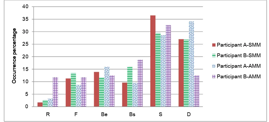
[image:10.595.111.492.387.459.2]Figure 4. Design issue distributions of participant A and B in SMM and AMM sessions
Figure 5 presents the aforementioned two design issue distributions in sketching and CAD modelling in SMM and AMM design sessions. A comparison of the two participants’ results shows that the total distribution of documentation (D) in SMM is similar as is the percentage for using sketching and CAD modelling. On the other hand, participant-A produced a higher percentage on documentation (D), and a higher percentage on sketching and CAD modelling distributions than participant-B. There are a number of reasons why participant-A’s switches changed the design issues from structure (S) to documentation (D) when switching from sketching to CAD modelling: ‘Transferring the sketch plan to the CAD environment’ and ‘Then moved it onto CAD’, as defined for the first type of design switch (S→C) in the context of the paper. Referring to Table 1, the segment for making a new component in CAD should be coded as structure (Sc). However, for the reasons mentioned above, for design switch (S→C), the same segment will change to documentation (Dc) because the participant transferred sketches into CAD.
0 5 10 15 20 25 30 35 40
R F Be Bs S D
O
cc
urre
nc
e
pe
rc
en
ta
ge
Figure 5. Documentation distributions of participant A and B in sketching and CAD modelling
[image:12.595.87.521.477.664.2]Figure 6 shows how participant-A facilitated the design process when switching between media. First of all, the participant found it challenging to locate an appropriate place for a stair using CAD. The participant therefore switched to sketching (C→S) to refine and evaluate different locations. Once satisfied, the participant transferred the sketches in CAD (S→C).
Figure 6. Examples of participant-A design switches
Figure 7 shows that participant-B produced the highest percentage for requirements (R) because of regularly switching between media and the design brief. The reasons given included:
‘I moved from sketching to the CAD environment because I wanted to start designing in a virtual setting to understand the spatial and scale requirements of the brief. I noted that as
0 5 10 15 20 25 30 35 40
O
cc
urre
nc
e
pe
rc
en
ta
ge
Documentation
the 3D model is readily available, I can begin to make immediate changes to form the new design proposal’;
‘I noted that I was cross-checking the requirements of the brief so I can keep on task with my current design intentions’; and
‘In the final stages of completion, I noted that I was switching back and forth so I can check that I have satisfied the requirements of the set brief’,
[image:13.595.144.457.298.537.2]The participant was switching back and forth between sketching/CAD modeling and design brief, as defined for the second type of design switch (S/C↹R) in the context of the paper. In addition, this type of design switch refers to Cross and Drost (1999) and Suwa et al. (2000)’s protocol studies such as ‘situative invention (S-invention)’ and ‘co-evolution’. Cross and Dorst (1999) posited the modelling of design creativity as a co-evolution for both problem and solution spaces. According to Suwa et al. (2000), S-invention refers to designers’ activities that extend beyond the initial definitions of the problem-space, helping designers to form new goals to address significant parts of design problems.
Figure 7: Requirement distributions of participant A and B in sketching and CAD modelling
DISCUSSION
In general, sketching allows design solutions to be stored and subsequently evaluated. This helps designers recognise different design possibilities (Akin, 1978). By contrast, it is not possible to store alternatives on a screen when CAD modelling is used. Designers need to undo and redo their CAD models when changes are required. The two design processes, SMM and AMM, may lead to changes in the roles of design mediums. Using AMM (i.e. being able to switch between media) allows designers to engage effectively in their design processes and find appropriate solutions to problems. For instance, Figure 6 shows that participant-A was fully engaged in design processes using AMM. However, participant-A mentioned ‘I get stuck’ several times during CAD designing section when using the SMM approach.
Participants’ comments
Participants provided comments on completion of both experiments. Their feedback about SMM was that they would not be capable of designing using CAD if they were not allowed to
0 2 4 6 8 10 12 14
O
cc
urre
nc
e
pe
rc
en
ta
ge
Requirement
switch. The common view was that if they were allowed to switch between media they would have evaluated their ideas quickly at both abstract and concrete levels. On the other hand, completing activities in AMM design environments were likened to tracing ideas between sketching and CAD modelling. Their view was that by switching between media they were able to complete their design tasks smoothly. This relates to the concept of the ‘right-tool-right-time’, (Do, 2005: 396) and that such usage would actually engage participants thinking along creative pathways.
All participants believed strongly that switches were essential. They summarised the contribution of being able to switch as follows:
1. Switching is essential: ‘I think the combination of sketching in tandem with CAD tools offers the designer a great freedom of design expression, having the ability to cognitively work between two mediums. This process of switching mediums, in my opinion, is the ideal design format for conceptualisation’.
2. Switching is a natural design workflow: ‘Many designers use sketching, mostly as visual notes, to rapidly memorise a design idea. CAD is useful to record the ideas and extend the development of the visual notes taken whilst thinking about the design and reflecting upon the design requirements. Using CAD as a permanent record of design ideas that are ever changing on paper helped me stabilise the design workflow. For me personally it was easy and natural to switch between mediums as it forms a very natural and complimentary workflow’.
3. Switching has potential for creative engagement with interactive mediums: ‘I found it quite natural to work in the AMM session, I felt I could achieve better results by sketching first and then going back to alter in tandem with the CAD tools provided’.
Categorisation of three types of switching between media
While Table 4 and Figure 6 demonstrated several design switches between media, the results of the study can be categorised into three types of switches:
1. The first type of design switch, from sketching to CAD modelling (S→C), changes a design issue of the FBS coding scheme from structure (S) to documentation (D): ‘I was trying the hand-sketched design in the CAD environment so as to better understand its function in terms of scale, section and elevation’ and ‘moved it onto CAD’.
2. The second type of design switch, back and forth between sketching/CAD modeling and design brief (S/C↹R) within seconds, evaluates the similarities and differences between sketches/CAD models and design briefs which was coded as requirements (R): ‘I was switching back and forth so I can check that I have satisfied the requirements of the set brief’.
3. In the third type of design switch, from CAD modelling to sketching (C→S), the participants preferred using sketching to refine their ideas than using CAD modelling: ‘I was sketching another spatial variation of the floor plan to better understand the spatial qualities at a conceptual level’.
Implications for design research and practice
This study compared cognitive behaviour in SMM and AMM design environments. It provides empirical evidence to better understand two approaches of integrating sketching and CAD modelling. The FBS coding scheme was developed to fit mixed media design environment studies and allow researchers to compare overall design processes as well as changes of cognitive behaviour within indiviual design mediums. The development of coding schemes and the techniques of combining these with switching protocols are transferable for future investigations about the integration of design mediums.
switching for more than one hour would have resulted in an excessive cognitive load which would have resulted in frustration and inertia. The switches between media require much less cognitive design process load.
CONCLUSION
The main question addressed in this study was whether participants’ switches between sketching and CAD modelling influence design processes. First, the results show that the designers switched many times between sketching and CAD modelling during AMM design processes. Second, two design issues (S and Bs) of the FBS coding scheme were changed to design issue (D) after switching from sketching to CAD modelling (S→C). A possible mechanism by which designers’ switches influence design processes is Do’s concept of ‘right-tool–right-time’, (Do, 2005: 396). This also supports Coyne et al.’s (2002) research with respect to the integration of conventional and digital methods for sketching: each is valued rather than one replacing the other. Some studies of cognitive behaviour (Chen, 2007; Ibrahim and Rahimian, 2011) have found mixed media to be the most effective external representation aids because they generate higher quality solutions than when CAD modelling is used in isolation. However, most participants in these studies were asked to initially use sketching before shifting to CAD modelling. Interestingly, in the study reported here, it was observed that both participants spent more time on CAD modelling than sketching. One advantage of this study is the AMM experimental set-up, which is close to the circumstances of natural design. In conclusion, this study has demonstrated that both participants’ switches were effective in influencing design processes because the switches integrated both sketching and CAD modelling as one design medium.
The current study is based on the two participants’ protocols in the SMM and AMM sessions combined with interviews about switching. These activities produced a large amount data and provided opportunities to test various experimental settings. However, the sample size of this study is more modest than other protocol design studies. To better understand mixed media studies, further investigations with a larger sample size will be conducted.
ACKNOWLEDGEMENTS
The authors would like to thank A/Prof. Ning Gu and Prof. Anthony Williams for their valuable guidance throughout this research, and the study participants for their involvement.
REFERENCES
Aish, R. (1986). Three-dimensional Input and Visualization, Computer-Aided Architectural Design Futures, CAAD Futures Conference Proceedings, 68-84.
Akin, O. (1993). Architects' Reasoning with Structures and Functions, Environment and Planning B: Planning and Design, 20, 273-294.
Akin, O. (1986). Psychology of Architectural Design, London: Pion.
Bilda, Z., & Gero, J. S. (2006). To Sketch or Not to Sketch? That is the Question. Design Studies, 27(5), 587-613.
BSS (1997). The Third Eye, Building Services Supplement, May, 8-9.
Candy, L, Bilda, Z, Maher, ML & Gero, JS (2004). Evaluating Software Support for Video Data Capture and Analysis in Collaborative Design Studies, Proceedings of QualIT04 (Qualitative Research in IT and IT in Qualitative Research) Conference, Brisbane, Australia, CD-rom, no page numbers.
Candy, L. & Edmonds, E. (1996). Creative Design of the Lotus Bicycle. Design Studies, 17(1): 71-90. Chen, Z. R. (2007). How to Improve Creativity: Can Designers Improve Their Design Creativity by Using
Conventional and Digital Media Simultaneously? CAAD Futures 2007, Proceedings of the 12th International CAAD Futures Conference, 571-583.
Coyne, R., Park, H., & Wiszniewski, D. (2002). Design Devices: Digital Drawing and the Pursuit of Difference. Design Studies, 23(3), 263-286.
Cross, N. (2001). Achieving Pleasure from Purpose: The Methods of Kenneth Grange, Product Designer.
Design Journal, 4(1), 48-58.
Cross, N. & Cross, A. (1995). Observations of Teamwork and Social Processes in Design, Design Studies, 16(2), 143-170.
Cross, N., & Dorst, K. (1999). Co-evolution of Problem and Solution Space in Creative Design, in J. S. Gero and M.L. Maher (eds.) Computational Models of Creative Design IV, Key Centre of Design Computing, University of Sydney, 243-262.
Do, E. Y. L. (2005). Design Sketches and Sketch Design Tools, Knowledge Based Systems (18) 383-405. Dorst, K. (1996). The Design Problem and its Structure, in N. Cross, H. Christianns and K. Dorst (eds.),
Analysing Design Activity, Chichester and New York: John Wiley, 17-35.
Dorst, K. & Dijkhuis, J. (1995). Comparing Paradigms for Describing Design Activity, Design Studies, 16(2), 261-275.
Eckert, C. M., Blackwell, A.D., Bucciarelli, L.L., & Earl, C. F. (2010). Shared Conversations Across Design.
Design Issues, 26(3), 27-39.
Ericsson, K. A. & Simon, H. A. (1993). Protocol Analysis: Verbal Reports as Data, Cambridge, Mass: MIT Press.
Ehrlenspiel, K. (1995). Integrierte Produktentwicklung, München: Hanser.
Gero, J. S. (1990). Design Prototypes: A Knowledge Representation Schema for Design. AI Magazine, 11(4), 26-36.
Gero, J. S., & Kannengiesser, U. (2004). The Situated Function-Behaviour-Structure Framework, Design Studies, 25(4) 373-391.
Gero, J. S., & McNeill, T. (1998). An Approach to the Analysis of Design Protocols. Design Studies, 19(1), 21-61.
Gero, J. S. & Sudweeks, F. (1998). Artificial Intelligence in Design ’98, Dordrecht: Kluwer.
Gero, J. S. & Tang, H. (2001). The Differences Between Retrospective and Concurrent Protocols in Revealing the Process-oriented Aspects of Design Protocols. Design Studies, 19(1), 21-61. Gross, M. & E. Y., Do. (1996). Ambiguous Intentions: A Paper-Like Interface for Creative Design.
Proceedings of the ACM UIST Conference, 183-192.
Goldschmidt, G. (1995). Visual Displays for Design: Imagery, Analogy and Databases of Visual Images, in Koutamanis, A., Timmermans, H. and Vermeulen, A. (eds), Visual Databases in Architecture; Recent Advances in Design and Decision Making, Aldershot: Avebury, 53–74.
Gordon, W.J.J. (1961). Synetics: The development of creative capacity, New York, Harper and Row. Goulding, J. S., Pour Rahimian, F., & Wang, X. (2014). Virtual Reality-based Cloud BIM Platform for
Integrated AEC Projects. Journal of Information Technology in Construction (ITCON), 19(Special Issue BIM Cloud-Based Technology in the AEC Sector: Present Status and Future Trends), 308-325. Ibrahim, R., & Rahimian, F. P. (2011). Comparison of CAD and Manual Sketching Sools for Teaching
Architectural Design. Automation in Construction, 19(8), 978-987.
Kan, J. W. T. & Gero, J. S. (2005). Can Entropy Indicate the Richness of Idea Generation in Team Designing? Proceedings of the 10th International Conference on Computer Aided Architectural Design Research in Asia (CAADRIA 2005), New Delhi, India.
Kan, J. W. T. & Gero, J. S. (2008). Acquiring Information From Linkography in Protocol Studies of Designing. Design Studies, 29(4), 315-337.
Lawson, B. R. (2002). CAD and Creativity: Does the Computer Really Help? Leonardo, 35(3), 327-331. Lewis, R. & Sequin, C. (1998). Generation of 3D Building Models from 2D Architectural Plans,
Computer-Aided Design, 30(10), 765-779.
Lin, C. (2003). Seeing Moving Seeing Model for Computer Media, 8th International Conference on Computer Aided Architectural Design Research in Asia, Bangkok, 199-208 .
Newell, A. (1990). Unified Theories of Cognition. Cambridge, Mass: Harvard University Press.
Osborn, A. F. (1963). Applied Imagination: Principles and Procedures of Creative Problem-Solving. New York: Scribner.
Reffat, R. (2002). Three-Dimensional CAD Models: Integrating Design and Construction, in R. Best and G. de Valence (eds), Innovation in Design and Construction: Building in Value, Oxford: Butterworth Heinemann, 291-305.
Robbins, E. (1994). Why Architects Draw, Cambridge Mass: MIT Press.
Romer, A., Pache, M., Weißhahn, G., Lindemann, U. & Hacker, W. (2001). Effort-Saving Product Representations in Design-Results of a Questionnaire Survey. Design Studies, 22(6), 473-491. Sachse, P., Leinert, S. & Hacker, W. (2001). Designing with Computer and Sketches, Swiss Journal of
Psychology, 60(2), 65-72.
Salman, H. S., Laing, R. & Conniff, A. (2014). The Impact of Computer Aided Architectural Design Programs on Conceptual Design in Educational Context. Design Studies, 35 (4), 412-439. Schön, D. A. (1992). Designing as Reflective Conversation with the Materials of a Design Situation,
Knowledge-Based System,(5.1), 3-14.
Sobek, II, D. K., & Jain, V. K. (2004). Two Instruments for Assessing Design Outcomes of Capstone Projects, Proceeding of the 2004 American Society for Engineering Education Conference and Exposition.
Suwa, M. & Tversky, B. (2001). How Do Designers Shift Their Focus of Attention in Their Own Sketches? In Anderson, M., Meyer, B. and Olivier, P. (eds.) Diagrammatic Reasoning and Representation, Berlin: Springer, 241-260.
Suwa, M., & Tversky, B. (1997). What do Architects and Students Perceive in Their Design Sketches? A Protocol Analysis, Design Studies, 18(4), 385-403.
Suwa, M., Gero, J., & Purcell, T. (2000). Unexpected Discoveries of Design Requirements: Important Vehicles for a Design Process, Design Studies, 21(4), 539–567.
Tang, H. (2001). Exploring the Roles of Sketches and Knowledge in the Design Process. PhD thesis. The University of Sydney, Department of Architectural and Design Science. Faculty of Architecture. Tang, H. H., Lee, Y. Y., & Gero, J. S. (2011). Comparing Collaborative Co-Located and Distributed Design
Processes in Digital and Traditional Sketching Environments: A Protocol Study Using the Function-Behaviour-Structure Coding Scheme. Design Studies, 32(1), 1-29.
Van Someren, M. W., Barnard, Y. F., & Sandberth, J. A. C. (1994). The Think Aloud Method: A Practical Guide to Modelling Cognitive Processes. London: Academic Press.
_______________________________________________
AUTHORS
Yi Teng Shih Assistant Professor
The University of Nottingham, Faculty of Science and Engineering Yi-Teng.Shih@nottingham.edu.cn
William D. Sher Associate Professor
The University of Newcastle, Faculty of Engineering and Built Environment Willy.Sher@newcastle.edu.au
Mark Taylor Professor