University of Warwick institutional repository: http://go.warwick.ac.uk/wrap
A Thesis Submitted for the Degree of PhD at the University of Warwick
http://go.warwick.ac.uk/wrap/66932
This thesis is made available online and is protected by original copyright. Please scroll down to view the document itself.
Microstructure and Mechanical Performance of
SiC/BMAS Glass-Ceramic Matrix Composite
Grant West
Thesis
submitted for the award of
Doctor of Philosophy
Centre
for Advanced Materials
University of Warwick
Acknowledgements
During this PhD I have received help from a great many sources. In particular I would like to thank Professor Mike Lewis for providing the opportunity to work at the
University of Warwick and his help and guidance as my supervisor. Thanks also to my former supervisor Professor David Taplin.
It has been my pleasure and privilege to work alongside colleagues in this field who have inspired me and been great friends. In particular, gratitude is due to Drs Markys Cain and Aldo Boccaccini for numerous informative discussions. I must also thank past and present friends from the Department of Physics such as Drs Kevin Plucknett, Tony Chamberlain, Astrid Nordmann, John Lumby as well as Rebecca Cain.
Technical assistance has been gratefully received from many sources within the department such as Gerry and Steve on the electron microscopes, Adrian Lovejoy for his electronics guidance and noise detection on the Instron and Dave Hammond for his aid with the Instron and dilatometer.
Having worked on this project at two different Universities I must also thank the staff of the University of Plymouth, David Short and Dr David Plane particularly, for their help.
Declaration
This thesis is entirely my own work unless otherwise referenced and has not been submitted for award of a degree at any other University. The thesis is set out as as per the guidelines issued by the Warwick Graduate School (September 1996). Parts of this work have appeared in numerous publications as listed below:
Cyclic creep response and creep recovery of continuous fibre reinforced glass and glass-ceramic matrix composites,
G West, A R Boccaccini, J Janczak, D M R Taplin and M H Lewis, Submitted to ICSMA-I I, Prague,
25-29 August 1997
Mechanical behaviour and environmental stability of continuous fibre-reinforced glass-ceramic matrix composites,
G West, D M R Taplin, A R Boccaccini, K Plucknett and M H Lewis, Glass Science and Technology,
Glastech Berichte, Feb 1996, Vol 69, No 2,pp34-43
Cyclic creep response of continuous fibre reinforced glass-ceramic matrix composites,
G West, A R Boccaccini, D M R Taplin and M H Lewis, ECCM-7, The Institute of Materials, Woodhead
Publishing Ltd, London, 1996 Vol 1,455-60
Creep and creep fatigue behaviour of continuous fibre reinforced glass ceramic matrix composites, G West, A R Boccaccini and D M R Taplin, Materielwissenschaft und Werksofftechnik 26,368-73, (/995)
Ceramic matrix composites; microstructure and thermostructural performance limits,
M H Lewis, A Tye, G West and M G Cain, Presented at NATO Advanced Research Workshop, Kiev,
Ukraine, June 2-61997
Mechanical properties of silicate matrix SiC yarn reinforced composites,
D M R Taplin, G West, A R Boccaccini and M H Lewis, ICF-9 in Advances in Fracture Research, Vol 2,
Eds Karihaloo B L, Mai Y-W, Ripley M I and Rotchie R 0, Pergamon (1997), ppl127-34
Tensile behaviour and cyclic creep of of continuous fiber-reinforced glass matrix compoistes at room and elevated temperatures,
A R Boccaccini, G West, J Janczak, M H Lewis and H Kern, Journal of Materials Engineering and
Performance, Vol. 6, No 3, 1997,pp344-348
Kriecherm Y dungserscheinungen von faserverstSrkten Glaskeramikmatrix-Verbundwerkstoffen,
A R Boccaccini, G West, D M R Taplin and M H Lewis, Werkstoffwoche '96, Stuttgart, 28-31 May 1996.
(Poster presentation).
Fracture behaviour and creep fatigue response of fibre reinforced glass-ceramic matrix composites, A R Boccaccini, G West and D M R Taplin, Physicochemical Mechanics of Materials, Vol. 32, 1, (1996),
81-90
Environmental ageing effects in a silicon carbide fibre-reinforced glass ceramic matrix composite, K P Plucknett, S Sutherland, A M Daniel, R L Cain, G West, D M R Taplin & M H Lewis, J. of Microscopy, Vol. 177, Pt 3, March 1995, 251-263
Continuous fibre reinforced glass ceramic matrix composites: microstructure, mechanical behaviour and environmental stability,
K P Plucknett, G West, D M R Taplin, A M Daniel, S Sutherland, R L Cain and M H Lewis, In
Summary
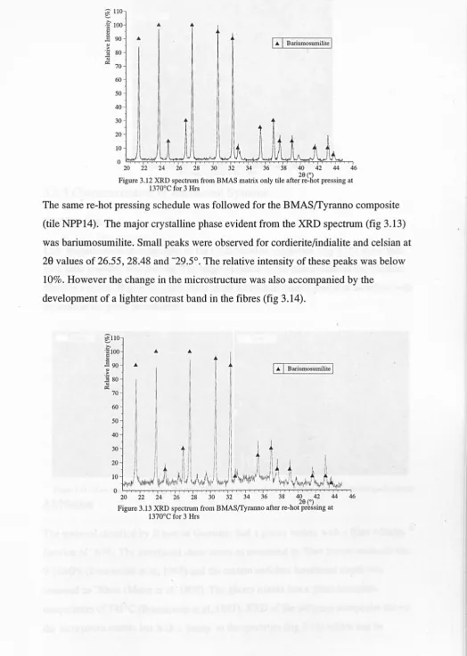
A diverse range of microscopy techniques and mechanical testing methods have been used to characterize glass and glass-ceramic composites. The focus of the work has been a commercially available Barium Magnesium Aluminosilicate matrix reinforced by Tyranno SiC based yam type fibres. The mechanical behaviour has been related to the microstructure through use of models from the literature. The temperature range of study has been from room temperature to 1300°C in air.
The microstructure of the BMAS(fyranno was a diphasic mixture of celsian and indialite/cordierite although the manufacturers intention was a monophasic
bariumosumilite. The carbon rich interface was found to be thin (l0-15nm) but the composite displayed impressive strength when compared to similar glass-ceramic composites reported in the literature. The matrix could be converted to the equilibrium bariumosumilite phase by heating in an inert atmosphere at 1370°C (or possibly lower) but matrix elemental diffusion into the fibres is likely to impair fibre strength.
Tensile failure was by conventional matrix microcracking with load transfer to the in line fibres. However the composite strength was found to be dependent upon the strain rate as was the microcracking threshold associated with cracking of the 0° plies. Failure of the UD BMAS(fyranno was by longitudinal splitting before the expected ultimate strength (from the 0,90° results) was reached. This was due to an apparent notch sensitivity in this fibre architecture, a trait not observed in the 2-D composite.
Direct measurement methods were used to establish the interfacial shear strength and these were compared to various models. These were based on matrix cracking
thresholds, matrix crack spacing and a relatively new method where an 'inelastic strain index' was found from loading and unloading curves or hysteresis loop widths. Greatest fidelity with the direct methods was found with the last of these models.
As with all composites with carbon enriched interfaces oxidation of the interface and fibres was found to impair strength when tested in air at temperatures as low as 600°C and possibly below this when testing at lower strain rates. At high strain rates, near room-temperature-strengths were achieved, even at 1l00°C, as the degrading effects of the oxidizing environment had less time to act. Long term exposure at high
temperatures (1200°C) was responsible for formation of an embrittled surface layer up to 70J.lm thick. Within this layer the fibres were severely degraded and strong bonding prevailed at the interface.
At temperatures in excess of the expected fibre pyrolysis temperature, (l100°C), the composite was seen to shrink along the length of the fibre axis and dilate normal to it which was attributed to fibre instability. Stabilising the fibres by heat treatments at 1200°C for 24 hours was seen to improve the creep performance in terms of the total strain accumulated within the 100 hours of the creep tests. The creep was comparable to other commercial glass ceramics (CAS/Nicalon and BMAS/BN/SiC/Nicalon)
indicating the dominance of fibre creep properties on those of the composite.
Cycling of the creep load seemed to result in a greater embrittled depth from the surface but failure at 100MPa and 1200°C was not observed within 240 hours of testing.
Other systems were investigated such as the CAS/Nicalon, MAS/Nicalon and AS/ Nicalon. Of these the AS/Nicalon was used for modelling the creep behaviour since it represented a simple system where matrix creep was accompanied by elastic
Contents
Acknowledgements
Declaration ii
Summary 111
Contents IV
Abbreviations Vll
Chapter 1 Introduction 1
1.1 High Temperature Engineering Materials 1
1.2 Ceramics 2
1.3 Fracture Mechanics 3
1.4 Wei bull Statistics 4
1.5 Toughening Methods 5
1.5.1 Transformation toughening 6
1.5.2 Pre-stressing 6
1.5.3 Microstructural Modifications 6
1.5.4 Second Phase Reinforcement 7
1.5.5 Long Fibre Reinforcement 7
Chapter 2 Review of Long Fibre-Reinforced Brittle Matrix Composites 9
2.1 Glass and Glass-Ceramic Matrix Composites 9
2.2 Fibres 12
2.3 Monotonic Stress-Strain Behaviour 15
2.3.1 UD BMCs 17
2.3.2 Cross Ply BMCs 20
2.4 Interfaces 20
2.4.1 Interfacial Shear Stress Evaluation 22
2.4.2 Interface Stability 23
Chapter 3 Experimental Techniques and Materials Characterization 27
3.1 Composite Systems 27
3.2 Mechanical Testing Techniques 28
3.2.1 Mechanical Test Specimen Preparation 28
3.2.2 Flexural Testing 29
3.3 Material Characterization
3.3.1 Electron Microscopy (SEM & TEM) 3.3.2 X-Ray Diffraction (XRD)
3.3.3 Characterization of Additional Systems
3.3.4 Thermal Expansion
3.3.5 Interface Techniques
3.3.6 Discussion
3.4 Conclusions
Chapter 4 Room Temperature Mechanical Properties 4.1 Flexure Testing
4.2 Tensile Testing
4.2.1 Monotonic Testing
4.2.2 Models for 't Evaluation
4.2.3 Tensile v Flexure
4.3 Load Cycling
4.3.1 Incremental Cycling
4.3.2 Cyclic test with prolonged hold
4.4 Notch Testing
4.4.1 Notch sensitivity of Cross Ply BMAS(fyranno
4.4.2 Notch testing of UD BMAS(fyranno
4.5 Interfacial Properties from Cyclic Loading
4.6 Conclusions
Chapter 5 Elevated Temperature Mechanical Behaviour 5.1 Flexure Testing at Temperature for 0,90 BMAS(fyranno
5.2 Strain Rate Effects
5.2.1 Flexural Strain Rate Testing of BMAS(fyranno
5.2.2 Discussion
5.3 Heat Treatment of UD BMAS(fyranno
5.3.1 Results and Observations
5.3.2 Discussion
5.4 Conclusions
Chapter 6 Time Dependent Properties at Elevated Temperatures 6.1 Review of Time Dependent Properties
6.2 Flexural creep and cyclic creep of BMAS(Tyranno
6.2.1 Flexural Monotonic Properties of UD BMAS(fyranno
6.2.2 Flexural Creep of UD BMAS(fyranno
6.2.3 Flexural Cyclic Creep of UD BMAS(Tyranno
6.2.4 Discussion
6.3 Tensile Creep of UD BMAS(Tyranno
6.3.1 Monotonic Tensile Properties of UD BMAS(fyranno
6.3.2 Tensile Creep Testing
6.3.3 Cyclic Creep of UD BMAS(fyranno
6.4 Tensile Creep of UD Aluminosilicate/Nicalon
6.4.1 Monotonic Tensile Properties of UD AS/Nicalon
6.4.2 Cyclic Creep of AS/Nicalon
6.5 Modelling of High Temperature Behaviour
6.6 Discussion
6.7 Conclusions
Chapter 7 Conclusions and Suggestions for Further Work 7.1 Conclusions
7.2 Suggestions for Further Work
References Appendix I
115
116
117 119
122
126
127
127
132
135
136
137
139
143
145
148
148
151
r
ACK ADR AS BAS BMAS BMC CAS CMAS CP CTE EDS GMC GCMC ITM LAS LDE LFRC MAS RT SDE SEM TEM UD XRDAbbreviations
Interfacial Shear Stress Debond Energy
Publication by Aveston Cooper and Kelly (see references) Actuator Displacement Rate
Aluminosilicate
Barium Aluminosilicate
Barium Magnesium Aluminosilicate Brittle Matrix Composite
Calcium Aluminosilicate
Calcium Magnesium Aluminosilicate Cross Ply
Coefficient of Thermal Expansion Electron Dispersive Spectroscopy Glass Matrix Composite
Glass-Ceramic Matrix Composite Inverse Tangent Modulus
Lithium Aluminosilicate Large Debond Energy
Long Fibre Reinforced Composite Magnesium Aluminosilicate Room Temperature
Small Debond Energy
Scanning Electron Microscope Transmission Electron Microscope Unidirectional
Chapter 1 Introduction
1.1 High Temperature Engineering Materials
It is the highest temperature applications that drive most of the current research into advanced structural ceramic materials as this is the area where the highest financial rewards would accrue. In this high temperature arena ceramics must compete directly with nickel based superalloys.
Particular applications have been identified which would maximise the potential of ceramic composites such as chemical processing equipment, where high temperature aggressive environments limit component longevity, or reciprocating parts for the mass produced car market where raising the engine's maximum temperature capability and reducing the reciprocating weight would respectively improve efficiency and maximum engine speeds. However one of the most difficult applications for these highly complex metal alloys is in the gas turbine engine where, as turbine blades, they perform at up to 80% of their melting temperature (for nickel based superalloys T m-1250°C (Raj 1993». The ideal efficiency of the gas turbine engine (1]) is governed by the turbine entry temperature (TET, T2):
(1.1 )
where TI is the heat sink temperature. If the maximum turbine temperature can be increased by using materials with higher temperature capability, the overall efficiency improves. However the main advantage of incrementing T 2 comes from the power improvement which is a linear function of temperature. Clearly improvement in the power to weight ratio means either physically smaller engines can be employed or the possibility of greater payloads. In order to reach such temperatures, superalloy turbine blades rely on a constant supply of cooling air forced centrifugally through small holes on the surface of the blade. This air cushions the blade from the extreme temperatures of the combustion process but can form up to 12% of the total turbine airflow (Stohr
1993). This cooling impairs the overall efficiency but does not negate the benefits of increasing the overall temperature capability.
oxidation, thermal fatigue and thermal shock. The implications of blade failure in jet
engines imposes the further criterion of fracture toughness for dealing with broken
compressor blades and bird strike debris. A possible specification could put a maximum
stress of -250MPa at take off and a limit of 0.1 % creep over 30 hours at 850°C. Under
such conditions grain boundary sliding and cavitation can be the limiting creep strength
mechanisms. Two major developments have seen these mechanisms lessen in
importance in turbine blades. In the 1950s the oxygen content was reduced by vacuum
melting. The second development introduced in the 1970s reduced the amount of grain
boundary perpendicular to the loading direction by the process of directional
solidification. Columnar grains can be grown parallel to the applied stress. This reduces
the driving force for grain boundary sliding to zero and lowers grain boundary
cavitation. The logical conclusion to this method is blades consisting of only one grain.
Thus the diffusional creep distances too are maximized.
Such developments have seen thrust to weight ratios more than treble from 3: 1 to 10: 1
and TETs increase from 800 to 1400°C from 1940 to the present day. Development of
nickel based superalloys has reached a point where there is limited scope for further
enhancement of maximum use temperature. It is hoped that ceramics will be able to
replace superalloy blades directly and, in doing so, dispense with the extra cooling with
an immediate impact on power and efficiency.
Use of more refractory metals with suitably low coefficients of thermal expansion
(CTE) has been considered as an alternative to nickel based alloys but invariably
candidates such as tantalum, molybdenum and tungsten suffer from poor oxidation
resistance.
1.2 Ceramics
Ceramics have the highest temperature capability of the three material groups.
Generically ceramics display good specific strength and stiffness to high temperatures,
exhibit high tolerance to oxidative and corrosive environments, have low thermal
expansion, are both thermal and electrical insulators and have wear and erosion
resistance due to their high hardness. This favourable blend of properties has resulted in
applications such as high temperature kiln equipment, furnace insulation and space
shuttle thermal protection, (where refractoriness is the main property required), cutting
environments) and radomes, (low coefficient of thermal expansion). A material
displaying all of these characteristics would seem ideal for most structural engineering applications. Ceramics, however, have a major failing: inherent brittleness which leads to a lack of reliability. This unreliability stems from the small size at which defects become critical. The ceramic under load may fail unpredictably. Other considerations lie in the processing of high temperature ceramics: their refractory nature necessitates high processing temperatures. Their hardness also makes it difficult and expensive to machine to the desired net shape as diamond grinding could be necessary. It is for these reasons of unreliability, lack of ductility, forming problems and the necessity for near net shape forming which has limited the development of industrial structural ceramics to date.
Strength predictions for glass based on O"u=E/I0 arguments suggest strengths of up to 100Pa. However such theoretical strengths are not approached in reality. It is the presence of flaws that limits the fracture strength. These flaws may be present as pores, surface scratches, isolated inclusions or other stress concentrating defects. The flaws may be pre-existing within the bulk of the material from manufacture or result from machining damage or even environmental attack. The small size at which these defects affect the ceramic's fracture strength means they are difficult to detect. Study of the effects of stress raisers such as defects and flaws has produced the discipline of fracture mechanics.
1.3 Fracture Mechanics
Under an applied load a material will deform elastically. Stress will concentrate at flaws. If the load is continuously increased a critical stress may be reached sufficient to propagate a crack from the critical flaw. If the energy used to create the new fracture surfaces is equivalent to or exceeds the elastic energy lost from the system the crack remains stable at its new length. If not, the elastically stored energy will provide the driving force for catastrophic failure. In metals the stress at a crack tip creates a plastic process zone, a consequence of which is a reduced elastic energy and a lower driving force for crack propagation, i.e. crack shielding occurs through plastic processes at the crack tip. A typical ceramic has no method of reducing the stress intensity at a crack tip so crack propagation can continue unabated under such conditions.
which were considered as elliptical holes:
0.2)
Where a and r are the crack length and crack tip radius respectively and am the maximum stress at the crack tip. The smaller the value for r the greater the maximum stress at the crack tip. It was Griffith (1920) who related the fracture strength of the material (af) to the flaw size (a), modulus of elasticity (E) and the surface fracture energy (y). By energy balance arguments he found what has become the cornerstone of fracture mechanics:
( 1.3)
Irwin (1958), through work on the stress field at a crack front, defined a material property called the critical stress intensity factor (Kc), or KIC for plane strain
conditions, more usually called the fracture toughness. This is a measure of a materials resistance to fracture and is given in:
(1.4)
Where Y is a dimensionless constant dependent on loading and specimen geometry. For monolithic ceramics the fracture toughness can vary from 0.2MPa.ml/2 for concrete up to 5MPa.ml/2 for alumina and silicon nitride to 8MPa.m 1/2 for diphasic 'Syalon' (Lewis, 1989). Equations 1.2 to 1.4 show the importance of the length and acuity of a crack or flaw on the fracture strength. The size and distribution of flaws therefore has a statistical effect on the fracture stress and therefore dictates the maximum strength. This means large factors of safety (FOS) must be used whenever ceramics are used structurally. The magnitude of the FOS necessary can be assessed by statistical methods.
1.4 Weibull Statistics
approach it is assumed failure occurs at a critical flaw by weakest link theory. For ceramics the Weibull function can be expressed as:
(a-a
)m
f(a)= _ _ f.1.ao (1.5)
where 0"f.1 is the threshold stress below which no failure is expected, 0"0 is a parameter
taken as the stress which represents a probability of failure of 63.2% and m is the Weibull modulus. Large m values represent narrow flaw distributions and small flaw sizes and hence low strength data scatter. The volume of a component stressed has a large effect on data scatter since a larger sampling volume is likely to experience a larger flaw popUlation. When a volume dV is considered, the probability of failure (F) is found to be:
(1.6)
The m value is a measure of reliability or predicted reliability. For different loading regimes the volume under consideration varies considerably. In uniaxial tensile loading the whole gauge section volume is considered, for other modes the effective volume is less.
Methods of improving the reliability of ceramics can therefore concentrate on two different approaches (Evans, 1990): reduce the quantity and size of flaws or somehow improve the ceramics fracture toughness. The former method relies on identifying the stages during processing at which flaws are introduced and eliminating them.
Toughening methods will now be discussed as the material systems used within this work are based on this approach.
1.5 Toughening Methods
Toughening of ceramics is an approach which recognizes flaws are inherent and cannot be completely removed. A major failing of the flaw reduction approach to improving the fracture strength of ceramics comes from the possibility of post processing damage which can be introduced in final machining or in service. Toughening accepts such imperfections and permits a degree of damage tolerance.
martensitic phase transformations and reinforcement with a second phase. These methods rely on preventing crack initiation or once developed, impeding crack propagation.
1.5.1 Transformation toughening
This method of toughening relies on the metastable phase transformation of tetragonal zirconia to the monoclinic equilibrium structure in the presence of a large elastic strain. The monoclinic phase has a less efficient atomic packing and so tries to assume a larger volume C3% volume increase). The martensitic reaction therefore applies a closing force on the advancing crack. Toughening is therefore improved as the crack grows, this is referred to as rising resistance or R-curve behaviour (Evans, 1990). The tetragonal phase is retained within the structure by cooling from above the phase transformation temperature of 1150°C. The fracture toughness can be increased to -lOMPa.m1/2. Toughening can be compromised with rising temperature as the driving force for the tetragonal phase conversion to monoclinic is reduced.
1.5.2 Pre-stressing
This method of improving the strength depends on reducing the tensile stress at likely crack initiation sites in a brittle solid thereby reducing the crack opening force when a load is applied. In this way a crack can only propagate from a flaw when a force large enough to overcome the compressive stress and reach the critical stress at the critical flaw is applied. The pre-stress can be achieved in several ways. For glass, surface prestressing by rapid quenching can be used where the surface cools more rapidly than the interior. Ion exchange can also be used to induce surface compression by
substitution of larger ions at the glass surface.
Long fibres can also be used to compress ceramics as with concrete where steel rods are elastically stretched. The concrete is then poured around them and allowed to set. Releasing the fibre stress pulls the concrete matrix into compression.
1.5.3 Microstructural Modifications
the random grain orientation thus crack propagation requires greater energy. Further toughness enhancement can be provided by elongation of the grain structure.
1.5.4 Second Phase Reinforcement
Toughness increments can be achieved by inclusion of a second phase such as particles to form a composite. The shape and volume fraction of the particles greatly affects the degree of toughening. The degree of toughening generally follows the aspect ratio of the second phase with the maximum toughness supplied by long fibre reinforcement. The aspect ratio and reinforcement alignment determine how successfully a crack can be bridged and therefore the amount of force acting to close the crack. Crack bridging is not the only mechansim active when a second phase is incorporated. Microcrack
toughening and crack deflection are also active but make small contributions compared to that of crack bridging. Spherical, platelet, rod, whisker and fibre reinforcement are all examples of this toughening method.
1.5.5 Long Fibre Reinforcement
Toughening by long fibres involves several different mechanisms. A propagating crack's progress can be impeded, or arrested, at the reinforcement or deflected at the interface. Bridging by the fibres in the crack wake may resist further extension. All of these mechanisms absorb energy so greater energy is necessary to cause failure. Further cracks will form leading to a microcracked matrix which in itself provides a degree of toughening. Intuitively the energy necessary to drive a number of cracks through a material is more than that needed to drive a single crack as more new surfaces are created. Ultimately, with increasing load, the bridging fibres fail and pull-out of the matrix and in doing so dissipate energy by frictional sliding.
Brittle matrices such as glass, glass-ceramic and ceramic matrices can be reinforced in this way to improve fracture toughness and strength. The important feature which governs the properties of such composites systems is the region between the fibre and the matrix. The interfacial bonding between the fibre and the matrix must be strong enough to transfer load yet weak enough to prevent crack propagation of the first crack through matrix and fibre.
over a wide range of loading conditions and temperatures. The applicability of the composite systems for critical engineering purposes is evaluated through the
experimental work presented in chapters 3 to 6. A review of the pertinent literature is presented in Chapter 2. The mechanical testing methods and equipment are detailed in Chapter 3 the latter half of which is concerned with microstructural characterization of the composites investigated in the subsequent chapters. The microstructural
Chapter 2 Review of Long Fibre-Reinforced
Brittle Matrix Composites (BMCs)
Research into 'modern' glass and glass-ceramic composites is not a recently developed field, rather an extension of work into brittle matrix composites (BMCs) that can be traced back to work on fibre reinforced cements. One of the goals of current research into BMCs across the globe is the development of tough, environmentally inert, high temperature structural composites for use in advanced applications such as the
aerospace market. Strength and stiffness increments, although welcome, are secondary desiderata to toughness.
Within this chapter the current work is placed within an historical perspective by review of pertinent areas of research which attempt to achieve this goal with glass and glass-ceramic matrix composites (GMC and GCMCs).
2.1 Glass and Glass-Ceramic Matrix Composites
Marked increases in the work of fracture (WoF) of several reinforced brittle matrices were achieved by Sampbell and Bowen (1972a,b). This was attributed to the effects of fibre pull-out. This early work on glass and glass-ceramic composite systems which incorporated carbon fibres in several matrices including glass, glass ceramic and ceramic matrices. Continuous reinforcement improved the flexural strength from less than 100MPa for the monolithic to 680MPa for the long-fibre reinforced Lithium Aluminosilicate (LAS) and borosilicate. However the oxidation of the carbon fibres above 400°C overshadowed the low temperature property improvements and precipitated a decline in research activity.
The renaissance of the early eighties was due to the development of a new silicon carbide yarn manufactured from a polycarbosilane precursor route by Yajima et al (1978). The yarn's greater oxidation resistance imparted a higher temperature potential. The commercial availability of the Nippon Carbon Company produced Nicalon fibre was first capitilized on by Prewo and Brennan in a series of papers on GMCs (Prewo and Brennan, 1980 and 1982) and GCMCs (Brennan and Prewo, 1982).
Prewo and Brennan (1980) who successfully managed to produce a unidirectional glass
matrix composite which displayed impressive flexural strength and toughness at
temperatures up to 700°C. The strength was limited by softening of the borosilicate
matrix. This was sufficient to prove the potential of SiC yam reinforced composites.
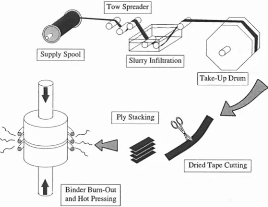
The manufacturing technique utilized a slurry infiltration processing route pioneered at
UKAEA Harwell for production of carbon fibre composites (Sampbell and Bowen,
1972b). Manufacture began with desizing of the fibres by passing through a Bunsen
flame. The yam was then passed through a glass slurry (fig 2.1) which infiltrated the
fibre tows. The slurry consisted of the matrix material finely powdered, a resin binder
and solvent. The tows were dried on a drum. Plies were then cut from the dried tapes.
The plies were stacked in a die for hot pressing. Densification was achieved by melting
the glass and hot pressing. The processing of GCMCs was ostensibly the same but with
a devitrification step, sometimes called 'ceraming', at an elevated temperature giving a
highly crystalline matrix with as little as 4% residual glass phase.
I
Slurry InfiltrationI
~
¢::]
,
Binder Burn-Out
and Hot Pressing
I Take-Up Drum I
[image:20.552.157.423.357.562.2]I
Dried Tape CuttingI
Figure 2.1 Schematic representation of hot pressing of slurry infiltrated fibre pre-forms
During fabrication a delicate balancing procedure is required to maximize the
toughness potential through weak interface development, minimise the level of porosity
and fibre degradation and control of matrix crystallization.
Different processing parameters can lead to great variations in the depth of the
interface: Pippel (1993) observed a Tyranno/SiC composite with a -lOnm C-rich layer
while Lewis an~ Murthy (1991) produced Nicalon/BAS with a 250nm Carbon
interface. Lowden (1991) has shown the interface thickness is inversely proportional to
composite mechanical behaviour through control of interfacial thickness.
The hot pressing pressure, temperature and time are critical to the composite properties. Temperatures above the glass liquidus enhance infiltration but may cause chemical damage and fibre grain growth. Conversely, selection of a low hot pressing temperature may lead to poor densification and mechanical damage of the fibre by hard glass
particles. Crystallization of the matrix must then be controlled as unwanted phases may induce excessive residual stresses at the interface and matrix such as cristobalite in borosilicate glass (Murthy and Lewis, 1989). Stresses at the interface can lead to high values of de bond and sliding resistance from high fibre clamping forces whilst within the matrix, microcracking and premature matrix failure can result.
Inevitably fibre damage cannot be avoided but processing can be optimized to minimize it. Prewo (1986) tested fibres before and after incorporation into a LAS matrix and found both the Weibull modulus and average strength (down from 2300 to 1500MPa) were compromised. Beyerle et al (1992a) measured fracture mirror radii of in-situ tested fibres and calculated the fibre bundle strength to be 0.420Pa against 1.80Pa for pristine fibres.
The Prewo and Brennan papers showed a borosilicate glass could be reinforced with Nicalon fibres giving a toughness approaching 20MPamY2 (fibre strength - 2GPa). The
flexural strength with temperature was only limited by the glass softening point. The delamination failure mode was indicative of a weak interface which they suggested was probably carbon on the fibres' surface. Oxidative stability of the composite was found to be excellent when exposed to air at 540°C (Prewo and Brennan, 1982). The
temperature range was extended by use of a high silica matrix (Prewo and Brennan 1982) which displayed impressive flexural properties to 1200°C in air.
1995; Wang, 1992). Other glass ceramics based on the alumino silicate system have been investigated but few have been available commercially. Such matrices include MAS, AS, CMAS, YMAS. A system made by ABA Harwell comprising the smaller diameter Tyranno SiC fibres and a Barium Magnesium Aluminosilicate matrix has been sold to several of the British Universities (Plymouth, Warwick, Queen Mary and
Westfield College) and has been selected as the basis of the current work.
2.2 Fibres
Two fibres based on silicon carbide dominate the market for fibre reinforcement of GMC and GCMCs. These fibres are Nicalon (Si-C-O) and Tyranno (Si-Ti-C-O). Both of these fibres are produced by pyrolysis of polycarbosilane precursors to form very fine grained off-stoichiometric yarns with diameters of -14J.lm and -8.5J.lm respectively. Nicalon, produced by Yajima et al (1978) was the first to gain market penetration after becoming commercially available from 1979-80 under Nippon Carbon Company (Japan) production. UBE Industries (Japan) have subsequently introduced a rival fibre under the name Tyranno, first tested by Yamamura et al (1987 & 1988) and Fischbach et al (1988).
The two fibres are not drastically different: both have nominally SiC compositions. In fact the majority is SiC (49mol% for Nicalon) present as a nanometer scale dispersion of ~-SiC crystals C3nm for Nicalon but less for Tyranno in the as received state). Free carbon is present within the structure as -lnm aggregates in Nicalon and surrounds the
~-SiC crystals in several turbostratic layers in Tyranno (Bunsell et aI, 1995). The
Table 2.1 Mechanical properties and chemical compositions of Nicalon and Tyranno fibres. Nicalon data from Ichikawa et ai, 1995; Tyranno from Berger et ai, 1996.
Properties Nicalon Hi-Nicalon Hi-Nicalon Tyranno Tyranno NL-200 'S' Lox-M Lox-E Diameter ().1m) 14 14 12 8.5 11
Tensile 3 2.8 2.6 2.5 2.9
Strength (OPa)
Elastic 220 270 420 180 199
Modulus (OPa)
Failure Strain 1.4 1.0 0.6 1.4 1.46 (%)
Density (g/cm ) 2.55 2.74 3.1 2.4 n/a
Approx. Grain 2.2 5.4 10.9 <2 2 Size (nm)
Chemical Composition
Siwt% 56.6 62.4 68.9 57 55
C 31.7 37.1 30.9 28 38
0 11.7 0.5 0.2 13 5
Ti 2 2
The mechanical performance of Nicalon and Tyranno when tested as isolated fibres is presented in Table 2.1. These strengths and elastic moduli appear high but must be compared to stoichiometric Sie which has an elastic modulus in excess of 41 OGPa. The properties of both Nicalon and Tyranno are known to suffer in aerobic environments. Pysher et aI, (1989), tested Nicalon and Tyranno in air and found the strength for both degraded above 800°e. Above this temperature the strength stabilized at approximately 1.5GPa for Nicalon and Tyranno up to 1200oe. Strength and stiffness rapidly decreased above this temperature. Ishikawa et aI, (1987), studied the effects of thermal exposure in air at 800, 100, 1200 and 1400oe, the strengths when tested under room temperature conditions were not affected at 8000
e for exposure durations of 10 hours or less. Exposure to 10000
e seemed to show a similar result with a minor drop of less than 200MPa over the same period. The thermal exposure results of Kim and Moorhead (1991) on Nicalon have shown degradation occurs at lower temperatures. Heat treatments at 8000
e in air with room temperature tensile testing has shown a rapid strength degradation for the first 1 to 5 hours from -2.8GPa to -1.9GPa (average
temperatures investigated, by the Ti additions (Table 2.1). This phenomenon has been used to explain fibre shrinkage at high temperatures (1200°C and over) for Nicalon (Simon and Bunsell, 1984) and Tyranno (Bunsell et aI, 1995) and also extended primary creep regimes during creep testing of individual fibres (Jia et aI, 1993) and composites (Wu and Holmes, 1993). The grain growth is normally associated with temperatures in excess of 1000°C but Kim et al (1991) claim grain growth at
temperatures as low as 700°C for long periods at temperature in Nicalon (164 hours) although similar findings are not available in the literature. The fibres also undergo a passive oxidation of the fibre surface which produces a silica layer the depth of which increases with time and temperatures as low as 700°C (Huger et aI, 1993). The Si02 layer can protect the fibre from oxidation (Mah et aI, 1984) but as the depth increases fibre embrittling may take place (Kim and Moorhead, 1991).
From the above it can be inferred the non-crystalline portion of these fibres controls the ultimate high temperature stability. The degree of non-crystallinity can be related to the oxygen content of the fibre implying greater stability can be imparted for compositions nearer to stoichiometric SiC. Recent developments of the Nicalon fibre have seen oxygen levels as low as 0.2 wt% for the new Hi-Nicalon
's'
due to a new electron beam irradiation method in an oxygen free atmosphere which prevents oxygen entering the fibre during the curing process (Okamura, 1987). The elastic modulus has been shown to increase dramatically with lower 0 content (Ichikawa et aI1995), see table 2.1. The fibre is not freely available yet but provides an exciting prospect for CMC and MMC development at high temperatures in the immediate future with its oxidation resistance to 1400°C and creep resistance to 1200°C (Ichikawa et aI, 1995). Tyranno have also produced a fibre by a similar route but the introduction of titanium to the fibre in the polymer precursor state as titanium alkoxide accounts for most of the final oxygen content of -5 % (Berger et aI, 1996). The lower oxygen fibres also have proven superior creep resistances over their original counterparts (Bunsell et aI, 1995).Several authors (Stewart et aI, 1987; Murthy et aI, 1989; Cooper and Chyung, 1987) have found oxidation to be more rapid for fibres in composite form. Processing into composite matrices also reduces fibre ultimate strength and Weibull modulus (Prewo,
(Fillipuzzi et aI, 1994).
The newest low oxygen fibres with their apparently superior properties, were not available at the initiation of this research. At the outset of this research programme composite manufacturers had selected the Nicalon 200 series or, to a lesser extent, the Tyranno LoxM fibres for composite reinforcement over the other fibres of Table 2.2 (Lewis, 1996). With greater availability of the recently developed low oxygen fibres, at reasonable cost, a new generation of GMCs, GCMCs and CMCs may become
available.
Table 2.2 Fibre types suitable for GMC, GCMC and CMC applications
Type Manufacturer Constitution Diameter Modulus Strength (11m) E (OPa) (OPa)
Nicalon Nippon Carbon Si-O-C 10-20 180 2 SiC Co. (Japan)
Tyranno Ube Industries Si-O-C-Ti 10-20 175 2 SiC (Japan)
HPZ Dow Corning Si-N-C-O 10-12 180-230 1.9-2.58
SiN Tonen Tonen Si-N 10 250 2.5
SiC (CVD) Textron SiC 140 406 3.5 -SCS6
Saphikon Al 0 Sapikon Inc. AI20 3 70-250 380 3.1 c-axis filament
Nextel610 3M aAlp3 (99%) + Fep3' Si0 2
10-12 370 1.9
2.3 Monotonic Stress-Strain Behaviour
Brittle materials suffer catastrophic failure when an applied load is sufficient for crack initiation from a critical stress concentrating defect. In such materials propagation is largely unimpeded.
,....
r
I [image:26.552.151.424.28.244.2]Crack Front Debonding
Figure 2.2 Toughening mechanisms in a tough BMC (After Evans and Zok. 1994)
The fibres provide bridging tractions which reduce the stress intensity at the crack tip. At the crack the fibres assume all of the load. The matrix stress recovers with distance from the crack faces within a characteristic slip length at a rate which is governed by the fibre/matrix interfacial shear stress ('t). In this manner further cracks may develop throughout the matrix. The cracks, which form perpendicular to the applied load when the fibres are aligned in the loading direction, reach a saturation spacing when the slip lengths overlap (A veston et aI, 1971). This microcracking introduces inelastic strains.
Once crack saturation has been achieved linear stress-strain behaviour may be reinstated but with a lower elastic modulus as the fibres assume the additional stress. Ultimately the fibres fail and, due to statistical flaw distributions, may fracture away from the final failure plane. Further toughening is provided as these broken fibres 'pull-out' of the blocks of matrix.
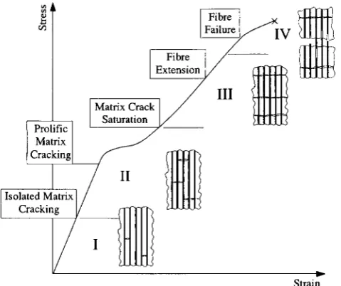
Thus various damage stages occur (fig 2.3):
Prolific Matrix Cracking
[image:27.552.167.407.35.236.2]Strain
Figure 2.3 Schematic representation of composite damage evolution during tensile loading. Based on Holmes. 1995
2.3.1 UD BMCs
Stage I: Within stage I no significant damage is manifest on a stress strain plot but various authors have shown isolated cracking events occur in matrix rich regions which have little effect on the elastic modulus as the cracks do not span the specimen (Kim and Pagano, 1991; Zawada and Butkus, 1991). The elastic modulus at this stage is given by the Voigt model or rule of mixtures (ROM):
where the matrix volume fraction is: V m= (1-V f)' where (V f) is the fibre volume
fraction,
(2.1)
Stage II: The matrix microcracking initiation condition for BMCs (stage II :crmc) where the fibre failure strain is greater than the matrix is given by A veston et al (1971) with an allowance for the matrix residual stress by Budiansky et aI, (1986):
(2.2)
where 't is a unique value for the fibre/matrix interfacial shear stress,
r
m the matrix fracture energy, R the fibre radius and q the residual axial matrix stress which may develop due to the high fabrication temperatures and thermal expansion mismatch between fibre and matrix which affects the cracking level. The matrix cracking level can be increased by increasing 't or decreasing Rand q. An important implication is theThe above equation has been verified by numerous studies but arbitrary selection of r m
and q can lead to disparities between different investigations (Beyerle et aI, 1992a). The
model provides a lower limit for multiple matrix microcracking which occurs over a
range of stresses due to the distribution in the inherent matrix flaw sizes (Marshall et aI,
1985, McCartney, 1987). Matrix cracking forms an important design parameter as it
signifies the onset of irreversible damage (Zawada and Butkus, 1991).
Toughening of BMCs is highly dependent on the fracture toughness of the fibre/matrix
interface (rD-This places a limitation on the ACK model (2.2) which suggests 1: can be
increased indefinitely. However in the presence of a 'strong' interfacial bond, fibres are
prone to rupture in the crack path. With a 'weak' interface fibre/matrix debonding
occurs in the crack path. He and Hutchinson (1989) place the following limitation for
debonding in the presence of a zero elastic mismatch:
Where
r
f represents the fibre fracture toughness, (fig 2.4).Interface ~
--
~-1.0Fibre Failure
0.5
Debonding
ED
-0.5 o O~ ID
[image:28.555.157.439.376.590.2]Elastic mismatch,
a
Figure 2.4 Interfacial fracture toughness requirements for debonding to occur. After He
and Hutchinson. (1989)
(2.3)
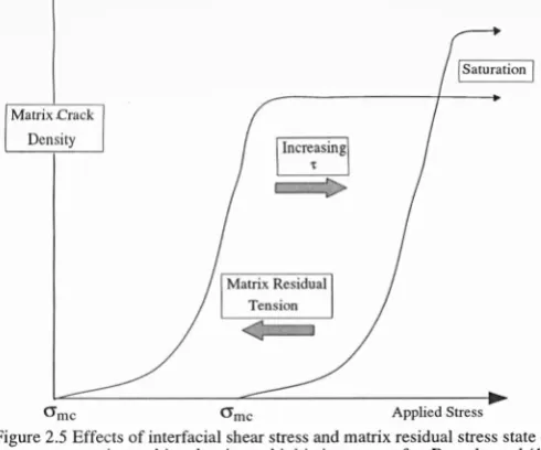
Further debonding may also occur in the crack wake (Charalambides and Evans, 1989).
The stability of the debonding stress is governed by the residual stress state at the
interface. Unstable, extensive debonding can prevail when the interface is in tension,
lower levels of debonding are indicative of residual compression (Evans and Marshall,
1989). The effects of interfacial sliding stress and matrix residual stress state are
O'me O'me Applied Stress
Figure 2.5 Effects of interfacial shear stress and matrix residual stress state on matrix cracking density and initiation stress after Beyerle et al (1992a)
Once the interface has debonded, the sliding resistance ('t) controls the load transfer
from fibre back to the matrix (A veston et aI, 1971). To a first approximation 't is the
product of the compressive stress at the interface and the coefficient of friction ()l), i.e.
F=pN. With a sufficiently low value of 't, fibre failure is more likely to occur remote
from the matrix crack plane. The fibre 'pUll-out' of the matrix at failure was resisted by
't which adds a toughening contribution. Extensive 'pull-out' has been seen for several
GMC (Prewo and Brennan, 1980) and GCMCs (Brennan and Prewo, 1982).
Matrix cracking continues until a saturation crack spacing develops when the slip
lengths of neighbouring cracks overlap. The mean final crack spacing lies between one
and two times the fibre to matrix load transfer length, x. This spacing therefore contains
information on 't for small debond energy composites. Kimber and Keer (1982) give the
mean final crack spacing as 1.3376 x x. Aveston et al (1971) calculated
x
=
(~
)
cr~~r
(2.4)where {jmu represents the unreinforced matrix failure stress.
Stage III: With saturation cracking of the matrix, load is accommodated by elastic
extension of the fibres. Thus it may be predicted that for fibres slipping within the
matrix 'blocks' the elastic modulus is simply the product of the fibre stiffness and fibre
volume fraction (Ec=VfEf).
Various studies have shown the final tangent modulus is actually lower than this
due to Poisson contraction of the fibres and fibre failures for the discrepancy. Stage IV: Ultimately the fibres fail according to a statistical strength distribution. Global load sharing ensures the composite does not fail with the first fibre fracture as the matrix blocks distribute the load to intact fibres across the plane in which the fibre failed (Curtin, 1991, Davis et aI, 1993). By this method the composite failure strain can actually exceed dry fibre bundle failure strains. Within a stress-strain plot the process of fibre failure can sometimes be seen as a reduction in the elastic modulus.
2.3.2 Cross
Ply
BMCs
For cross-ply laminates the stress-strain behaviour is similar but other damage stages are necessary to describe the complete failure behaviour.
Stage I described previously is terminated by transverse microcracking in the 90° plies by a tunnelling mechanism (Hutchinson and Suo, 1991). The applied stress at which cracking initiates depends on the residual stresses within the ply, the flaw sizes and distribution, matrix fracture toughness, fibre volume fraction and the ply thickness. The cracks form perpendicular to the applied load and reach a saturation crack spacing which is proportional to the ply thickness (Garrett and Bailey, 1977). These transverse cracks generally terminate at the 0° ply boundaries but may penetrate to several fibre depths (Wang, 1992).
At a second microcracking level, cracking in the 90° plies may extend into and across the 0° plies coincident with crack initiation within the aligned ply. After this threshold stress a comparison can be made between different fibre architectures by considering the fibre volume fraction in the loading orientation. For UD and 0,90° specimens which share the same volume fraction the 0,90° stress-strain behaviour (post 0°
microcracking) can be approximated by multiplying the UO stress by one half (Evans and Zok, 1994).
2.4 Interfaces
also be coated prior to composite fabrication with C or BN with the same effect (e.g. Cain et aI, 1993).
Prewo and Brennan (1980) suggested the delamination failure mode of a Nicalon reinforced borosilicate glass was due to a weak interface, probably carbon present on the surface of the nicalon fibres. Brennan (1986) identified an essentially amorphous, carbon rich interface and felt it was formed from the particular chemistry or
microstructure of the fibres used. Brittle and tough composites were investigated: the carbon layer was absent in the weak, brittle composite. However, Cooper and Chyung (1987) claimed the cryptocrystalline interface formed depended on the reaction of oxygen with silicon carbide in addition to the excess carbon present in Nicalon fibre by the reaction:
SiC + ~ --7 Si~ + C (2.5)
or by Benson et al (1988):
SiC + 2CO --7 Si~ + 3C (2.6)
Cooper and Chyung (1987) gave the silica concentration gradient as the driving force for the interface formation. The oxidation reaction of silicon carbide has also been shown to occur with pure silicon carbide whiskers in an alumina matrix (Lin et aI, 1988) but not when a silica layer exists on the as received whisker surface (Schoenlein et aI, 1988). Chaim and Heuer (1991) found an in-situ reacted carbon interface could also be formed in a-SiC and cordierite reaction couples. Thus reactions 2.1 and 2.2 could occur in stoichiometric SiC and non-stoichiometric silicon oxycarbides. However the kinetics of the two reactions were found to be enhanced for the off-stoichiometric fibres.
(Cooper and Chyung, 1987): The matrix Si02 activity is determined by the basicity thereby dictating the Si02 concentration gradient and the interface reaction kinetics. Cooper and Chyung (1987) suggested the reaction rate of the interface formation was more rapid due to the excess carbon in Nicalon and Tyranno fibres.
During interface formation matrix elements may diffuse into the fibre catalysing the nucleation and growth of ~-SiC. The diffusion band can be seen in TEM investigations (Murthy et aI, 1989). Tyranno has been shown to develop a thinner carbon rich
interface than Nicalon under identical processing conditions in a borosilicate matrix due to a lower level of free carbon and formation of TiC precipitates. In contrast the fibre diffusion band was much larger at 450nm v 250nm for the Nicalon fibre (Murthy et aI, 1990) caused by Tyranno's greater disorder and higher oxygen content.
2.4.1 Interfacial Shear Stress Evaluation
Many ways have developed to either measure the interfacial shear stress directly or find it by inference from the mechanical behaviour of the composite.
Of the direct methods a fibre can be either pulled out of the matrix of a specially manufactured test-piece, pushed-in by an indentor or pushed-through with similar equipment. A recent method which may also be utilised in the near future involves measurement of fibre strain in the presence of a matrix crack and applied stress by Laser Raman Spectroscopy (Bollet et aI, 1996).
The most widely used methods for direct measurement are the indentation techniques. Specimen preparation for push-in testing is the least laborious and does not require special fabrication, unlike fibre pull-out testing. For composites with weak interfaces the preparation of thin specimens for fibre push-though can also prove difficult. Fibre indentation was first employed by Marshall and Evans, (1985). Individual fibres are indented until fibre debonding and sliding are observed. The analysis for 't evaluation in the current study is taken from Marshall and Oliver, (1987), in which the slope of indent load (F) squared versus fibre displacement (u) provides a means for calculating the interfacial shear stress ('t) and the intercept provides the interface debond energy (2ri) since:
F2 2ri
u=
Problems exist with this analysis since Poisson expansion of the fibre under load is likely to increase the apparent sliding and debond resistances. Also the analysis assumes shear cracking (mode II) at the interface whereas mixed mode (I and II) may prevail at the debond crack tip. The former problem is only evident for large debond energy composites and is not generally of concern for GMCs and GCMCs. The latter point will tend to underestimate
r
i ,(Lewis, 1996).Indirect methods where 't can be inferred from macroscopic mechanical behaviour include crack spacing measurements, matrix cracking stress, hysteresis loop widths, crack opening and pull-out lengths. Of the indirect methods calculation from matrix crack spacing (I) has proved the most popular using (Marshall and Evans, 1985):
(2.8) Where arne represents the nominal matrix crack initiation stress, A. is a universal
numerical factor given by Kimber and Keer, (1982), as 1.3337 and the other symbols have their usual meanings.
Compared to the matrix crack spacing method measuring pull-out lengths can be laborious. As an alternative hysteresis loop widths have been the subject of a recent trilogy of papers from Santa Barbara and remain to be independently validated (see Chapter 4). However the accuracy of the indirect methods is dependent on the model initially but also unknowns such as values for the matrix fracture energy and the matrix residual stress as well as the individual moduli for the composite constituents.
2.4.2 Interface Stability
Flexural testing of GMC and GCMCs in vacuum or inert atmospheres showed
composite strengths could be retained to temperatures as high as 1200°C (Brennan and Prewo, 1982). However an Achilles heel was discovered in the mid 80's by several research groups (Stewart et aI, 1986; Prewo, 1983; Mah et aI, 1985b). At temperatures in excess of 600°C in air a severe strength degradation was observed. Mah et al (1985) identified oxygen as the embrittling specie in NicalonlLASII by varying the 0 content in an Ar-O mix. The minimum strength, which occurred at 900°C in air, was found to coincide with the matrix cracking stress at room temperature. It was postulated diffusion of oxygen was very fast and probably gained access to the fibre/matrix
under load. Only one crack was observed in each specimen tested at high temperature in air. This contrasted with the parallel microcracks they had previously observed at room temperature (Mah et aI1985a).
Stewart et al (1986) reported similar findings for Nicalon/LASIII and also in Nicalon/ BMASIII. The rate of oxidation was probed by testing at two strain rates. No oxidation effects were apparent for Nicalon/LASIII at the faster rate. While the degradation was also less severe at the higher rate for the BMAS composite it did appear more
susceptible to oxidation at the testing rates selected. The strength degradation was attributed to fibre oxidation rather than clamping between matrix and fibre.
Cooper and Chyung (1987) oxidized foils and found the carbon rich interface removed and replaced with a silica layer by the reaction:
SiC + ~ ~ Si~ + C (2.9)
subsequent to the carbon removal (Pharaoh et aI, 1993):
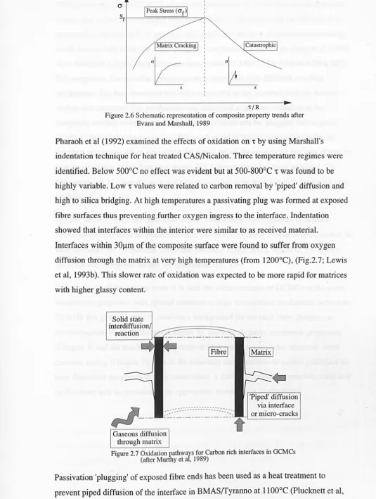
(2.10) The silica formed by this reaction strongly bonded the matrix to the fibre. At 900°C the reaction was noted within one minute. The ramifications are evident if equation 2.3 is considered: as
r
i increases andr
f decreases it becomes increasingly unlikely the interface/fibre fracture toughness ratio can be sustained below 0.25. With the 't
0-1 Peak Stress (cr f )1
Sff---=====~-~
I
Matrix CrackingI
£
[image:35.554.6.541.45.754.2]"C/R
Figure 2.6 Schematic representation of composite property trends after
Evans and Marshall, 1989
Pharaoh et al (1992) examined the effects of oxidation on 't by using Marshall's
indentation technique for heat treated CAS/Nicalon. Three temperature regimes were
identified. Below 5000
e
no effect was evident but at 500-800o
e
't was found to behighly variable. Low 't values were related to carbon removal by 'piped' diffusion and
high to silica bridging. At high temperatures a passivating plug was formed at exposed
fibre surfaces thus preventing further oxygen ingress to the interface. Indentation
showed that interfaces within the interior were similar to as received material.
Interfaces within 30llm of the composite surface were found to suffer from oxygen
diffusion through the matrix at very high temperatures (from 1200°C), (Fig.2.7; Lewis
et aI, 1993b). This slower rate of oxidation was expected to be more rapid for matrices
with higher glassy content.
Solid state interdiffu .
.---. ---.-.--- ---- --... -... -...
'Piped' diffusion via interface
or micro-cracks
Figure 2.7 Oxidation pathways for Carbon rich interfaces in GCMCs
(after Murthy et al, 1989)
Passivation 'plugging' of exposed fibre ends has been used as a heat treatment to
1994 and 1995). Heat treatments have also been performed at lower temperatures, e.g. Wetherhold and Zawada (1991) who found embrittling of an aluminosilicate/Nicalon system was halted by isothermal exposure to 800°C. The protection mechanism was presumed to be surface flow and smoothing although the lack of interface microscopy could conceivably mean the same 'plugging' mechanism is operative. Frety et al (1992) have also used a higher heat treatment temperature of 1400°C for lOOhours for a SiC/ SiC composite. Two similar composites were tested but with different interface thicknesses. The heat treatment was only successful in the material with the thinner carbon rich interface. The mechanism was identified as passive oxidation at the composite surface however the thicker interface could not be 'plugged' before gross interface degradation had occurred. Fillipuzzi et al (1994a,b) proposed a model for interface protection which calculated the rate at which the interfacial gap was closed by passive oxidation of the fibre and matrix (SiC) once carbon had been oxidized. The time necessary to close the pore entrance was found to be proportional to the pore size squared.
Surface sealing heat treatments enable high temperature investigations in aerobic environments but offer no protection once the matrix cracking threshold is exceeded. In such instances the mechanical behaviour becomes highly notch sensitive, i.e. matrix cracking and composite failure are concurrent (fig. 2.6).
Chapter 3 Experimental Techniques and
Materials Characterization
3.1 Composite Systems
Within the period of this work various material systems have been available. The original material supply was a unidirectionally Nicalon reinforced Magnesium
Aluminosilicate (MAS) supplied by Pilkington. Unfortunately the "ceraming" stage of the processing was under pressureless conditions outside the die. During the heat treatment bloating of the plies occurred resulting in poor quality composite. Very little data will therefore be presented here due to the low reproducibility of its mechanical properties.
A Coming Calcium Aluminosilicate/Nicalon system was also available in limited supply. This has proved sufficient for flexure testing at various temperatures and indentation and push-through studies.
Towards the end of this study an aluminosilicate glass matrix/Nicalon composite supplied by Schott of Germany via Dr. Boccaccini has been tested in the tensile mode. The lower temperature capability of the matrix has proved useful for testing under temperature conditions where the fibres are elastic but the matrix creeps extensively. The bulk of the results presented concentrate on the material supplied by AEA
Technology, Harwell. The Barium Magnesium Aluminosilicate (BMAS) has Tyranno fibre reinforcement and has been available in UD and Cross ply (0,90°) lay-ups. Harwell have also supplied a matrix only tile of BMAS although, as will be shown later, the microstructure and phases differ markedly from that of the composite. Early supply problems were overcome as were the difficulties with the quality of the product. Reinstatement of a binder 'burn-out' stage to the manufacturing process has reduced matrix porosity levels and resulted in composite Wei bull modulus values as high as 19.8. Table 3.1 contains details of all the most recent tiles used in this work
(Information from AEA Harwell and Sutherland and Cain, 1995). The Weibull moduli, flexural strength and standard deviations were obtained from 4 point bend testing of at least 20 specimens. The fibre volume fractions (V f) were supplied by the
Leuven partner of BRITE programme BE-461O. The original BMASfTyranno (designated 'OBM' from now on) was of a broadly acceptable standard, quality then deteriorated for the processing reasons described above. The tiles from 'NPPS' and onwards have been the most consistent and have shown the best mechanical properties.
Therefore three BMAS/fyranno designations exist: Original (OBM), very poor quality
(BNB 1) and the most recent high quality tiles (NPP5 to 20). The composite was made via the slurry infiltration route and is purported to be hot pressed at 950°C and
crystallized to bariumosumilite (BaMg2AI6Si9030) at 1350°C for three hours, (Churchman-Davies, 1996).
Table 3.1 Quality assessment of AEA Harwell supplied BMAStryranno
Tile Fibre Flexural Std. Dev. Weibull Vf Architecture Strength (MPa) Modulus (%)
(MPa)
NPP5 CP 649 64 10.7 -41.0
NPP7 CP 711 103 7.5 38.8
NPPIO CP 731 54 15.4 35.7
NPPll CP 704 60 13.4 39.1
NPP12 UD 1231 118 11.5 38.9
NPP14 UD 991 103 8.0 34.0
NPP17 UD 1180 82 16.2 33.0
NPP18 UD 1284 63 19.8 35.0
3.2 Mechanical Testing Techniques
The preferred manufacturing route for the composites tested here is by the hot pressing of pre-impregnated plies. This manufacturing technique does not lend itself to the production of intricate shapes. For this reason the product was supplied in plate form generally less than 3.Smm thick. Two sizes of plate were supplied, nominally
100xlOOx3.5mm and 220x220x2.5mm.
3.2.1 Mechanical Test Specimen Preparation
Samples for testing in flexure and tension testing were cut from the plates by different methods. The simple shape of flexural test bars (nominally 3x3x50mm) could be cut by several passes of a grinding wheel on a surface grinder (Jones & Shipman, 1400
cleaning in a heated methanol bath. The specimens were tested in the 'as cut' state. The selected shape (fig 3.1) of the tensile specimens required CNC machining. The cutting was by a single pass of a diamond tipped tool bit mounted in a pneumatic high speed spindle head on the Beaver NC5 145 CNC machine.
I
All dimensions in mmI
Figure 3.1 Schematic diagram of the tensile test geometry used within this programme
3.2.2 Flexural Testing
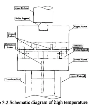
The flexural facility was supplied by Instron (High Wycombe) as a 'High Temperature Ceramics Testing System'. The long split furnace was manufactured by Severn
Furnaces Ltd (Bristol) and heated by six molybdenum disilicide elements. The flexure testing jig (Fig 3.2) had four pins, three of which rested on articulated rollers and the fourth rested on a rectangular section block and provided the alignment datum for the other articulated pins. The upper and lower jigs which held the pins and rollers had fixed spans of 20 and 40mm (upper and lower respectively). All of the components of the flexure jig were made from silicon carbide. Long alumina rods supported the fixture. The upper rod was solid and contacted the jig by a roller so as not to induce unwanted bend or torsion in the specimen. The lower rod was hollow. Deflection at the centre of the specimen was measured by an L VDT with ± Imm of travel which
contacted the specimen through a hole in the bend jig and the hollow lower support rod. The location and remoteness of the L VDT ensured it was not affected by the test temperature. At the base of the rod a thumbwheel permitted precise adjustment of the transducer zero point.
Upper Pushrod
Roller Support
[image:40.558.199.384.349.567.2]Lower Pullhrod
Figure 3.2 Schematic diagram of high temperature flexural testing facility
The rods were mounted on water cooled alignment rings and extra cooling for the 10kN load cell was provided by a heat shield above the furnace. The flexure testing
equipment was mounted inside the load frame of a servohydraulic Instron 8501. This provided the ability to control in either position or load modes from the Instron console. For high temperature work the temperature was ramped at a maximum rate of 15°C/ min. The temperature was allowed to equilibrate for 15 minutes before testing commenced.
an ADC/DAC podule capable of logging ±lOV at up to 10kHz supplied by SiPlan Electronics Research (Stratford-upon-Avon). "Basic" programs supplied by SiPlan were modified and tailored for the logging task with various sampling rates used from
several hundred data points per second when strain rate testing at the highest rates to one point every two second for long term testing. The data from such tests were analysed for discrepancies and 'pruned' down for reasonable file sizes for graphical presentation.
Monotonic loading in bend was at an actuator displacement rate of O.5mm/min. For strain rate testing this rate was changed to a maximum of 100mm/min and a minimum of O.OOlmm/min. For creep and cyclic creep testing load control was used for ramping to the selected load.
3.2.3 Tensile Testing
Testing in the tensile mode at Warwick on the Instron 1185 ball-screw driven universal testing machine has proved problematic. Electrical noise and temperature fluctuations within the room and water cooling and temperature instability of the extensometer due to proximity of the furnace have all had to be overcome or minimised before
meaningful results could be attained. The laboratory heating switched off at 2000hrs and on again at 0730hrs, these times were previously obvious in the long duration creep curves. This time scale does not affect short term testing but can lead to erroneous data during a typical creep test. To overcome such temperature differentials over the course of a test a lower capacity load cell was purchased (1 OkN as opposed to 100kN) as the drift specified by the manufacturers was quoted as a maximum temperature sensitivity of ±O.OOI %;oC of the load cell capacity. The extensometer was enclosed in a
temperature controlled box and the aluminium vertical bar on which the extensometer is mounted was drilled centrally to allow water cooling to maintain it at a constant
temperature. Water was supplied at a constant pressure to the pull-rod cooling collets, the alignment rings, extensometer and extensometer heat shield and mounting bar in series. The water was heated from the mains to the chosen temperature. The load cell was therefore maintained at a constant temperature as it was directly connected to the alignment rings.
The electrical ground was therefore supplied by the computer via the logging podule.
The specially built strain gauge amplifier (RS 435-692) was chosen for its temperature
stability and low noise. The extensometer (model no. 632.59C-Ol) was supplied by
MTS (Minneapolis, USA). The gauge length was set at 25mm and the gain on the strain
gauge amplifier was set to give a ±1OV output for ±O.5mm extension giving a
maximum measurable strain approaching 4%. The rods contacted the specimen as
chisel edges. Positioning on the specimen was maintained by a contact load of 100g per
rod. This force induced a bending moment in the specimen. The side the rods contact
experienced a compressive stress and similarly a tensile stress in the oppposite side.
The specimen geometry was based on a design by Holmes (1992). The specimens'
widths have been varied during the test: to reduce the bending stress imposed by the
contact extensometer thicker gauge widths were used generally for high temperature
testing. This was a particular problem for the aluminosilicate/Nicalon composite which
could viscously deform under such transverse loads at the upper testing temperatures.
For room temperature testing of UD materials it was necessary to use a thinner section
to prevent shear failure of the gripped ends. The pull rods were CNC machined from a
mechanically alloyed steel designated MA956. The pull-rods were located outside the
furnace hot zone but the 'warm gripping' precluded the use of normal steel alloy. The
gripping arrangement and tensile test apparatus can be viewed in figure 3.3.
Figure 3.3 Photographs of tensile testing facility. a) logg~g equipm~nt, fuma~e controller