University of Warwick institutional repository: http://go.warwick.ac.uk/wrap
A Thesis Submitted for the Degree of PhD at the University of Warwick
http://go.warwick.ac.uk/wrap/46969
This thesis is made available online and is protected by original copyright.
Please scroll down to view the document itself.
Supporting the Migration from Construal to Program:
Rethinking Software Development
by
Nicolas William Pope
Thesis
Submitted to the University of Warwick
for the degree of
Doctor of Philosophy
Department of Computer Science
Contents
List of Tables vii
List of Figures viii
Acknowledgments xvi
Declarations xvii
Abstract xviii
Abbreviations xix
Chapter 1 Introduction 1
1.1 Plastic Applications . . . 1
1.2 Plastic Software Environments . . . 4
1.3 A Lack of Plasticity . . . 6
1.4 Thesis Aims . . . 9
1.5 Thesis Outline . . . 10
Chapter 2 Background 13 2.1 End-User Development . . . 13
2.1.1 Principles . . . 14
2.1.3 Existing Environments . . . 17
2.1.4 Guidelines . . . 24
2.2 Empirical Modelling . . . 26
2.2.1 What is Empirical Modelling? . . . 26
2.2.2 The Principles . . . 32
2.2.3 Current Tools . . . 35
2.2.4 An Example Model . . . 38
2.2.5 EM and Software Development . . . 41
2.3 Miscellaneous Technologies . . . 43
Chapter 3 Enabling Plastic Applications 45 3.1 Empirical Modelling and Plastic Applications . . . 45
3.2 Dimensions of Refinement . . . 48
3.3 Limitations of EM Tools and Concepts . . . 51
3.3.1 Richness of Observables . . . 51
3.3.2 Analogue and Process Dependencies . . . 57
3.3.3 Notations and Agents . . . 61
3.3.4 Summary of Survey . . . 67
3.4 Looking for Solutions . . . 69
3.4.1 Richer Types and Semi-Structure . . . 70
3.4.2 Taking Advantage of Dependency . . . 72
3.5 A New Tool? . . . 74
Chapter 4 Cadence: A Prototype Tool 76 4.1 What is Cadence? . . . 77
4.2 Semi-structuring the OD-net . . . 78
4.2.1 How to Introduce Structure . . . 78
4.2.2 Developing a Textual Notation . . . 81
4.3 Making the OD-net Dynamic and Dynamical . . . 88
4.3.1 Computation by Navigation . . . 88
4.3.2 Definitions for Passive Dependency . . . 92
4.3.3 Definitions for Active Dependency . . . 96
4.3.4 Generic Definitions . . . 98
4.4 Implementing Cadence . . . 100
4.4.1 Architecture Overview . . . 100
4.4.2 Events and Queues . . . 102
4.4.3 Handlers and Agents . . . 106
4.4.4 C++ API . . . 107
4.4.5 Graphical Interfaces . . . 108
4.4.6 Other Extensions . . . 110
Chapter 5 Cadence Models and Examples 111 5.1 Stargate . . . 111
5.1.1 Shader Composition for Bloom Effect . . . 114
5.1.2 Applying Materials to a Model . . . 121
5.1.3 Use of Dynamical Dependencies . . . 125
5.1.4 Stargate Summary . . . 129
5.2 Hardware Device Drivers . . . 130
5.3 Network Distribution for a Video Wall . . . 132
5.4 Kinesin Biological Model . . . 135
5.5 Wii-fly Game and Presentation . . . 138
Chapter 6 Cadence Framework 142 6.1 The Concepts in Cadence . . . 143
6.1.1 Observables . . . 143
6.1.2 Relationships and Dependency . . . 147
6.2 Development Process . . . 156
6.3 Supporting Plastic Applications . . . 159
6.3.1 Supporting Personal Construals . . . 159
6.3.2 Supporting Public Programs . . . 165
6.3.3 Supporting Migration from Personal to Public . . . 167
Chapter 7 Cadence and Empirical Modelling 169 7.1 Cadence-in-Eden . . . 170
7.1.1 Cloning for Timetable and Bubble Sort . . . 175
7.1.2 Boolean Lattice Model . . . 178
7.1.3 Visualisation using the DMT . . . 180
7.2 Eden-with-Cadence . . . 183
7.2.1 Inter-Tool Communication . . . 184
7.2.2 Traffic Light System . . . 187
7.2.3 Timetable Revisited . . . 190
7.3 Cadence in the EM MSc Module . . . 194
7.3.1 Teaching Cadence . . . 194
7.3.2 Lab Sheets . . . 195
7.3.3 Coursework Models . . . 197
7.3.4 Student Feedback . . . 204
Chapter 8 Conclusions and Further Work 206 8.1 Contributions . . . 208
8.2 Further Work . . . 209
8.2.1 Larger Project and Complex Applications . . . 210
8.2.2 Interactive Development Environment . . . 210
8.2.3 Collaboration and Distribution . . . 211
8.2.4 Histories and Persistence . . . 211
8.2.6 Support for Meta-Relations . . . 213
8.2.7 Optimisations and Concurrency . . . 213
8.2.8 Formal Account . . . 214
8.3 Limitations of the Approach . . . 214
8.4 Looking Forward . . . 215
Appendix A DASM Scripts for Models 216 A.1 Stargate Scripts . . . 216
A.2 Wii-fly Script . . . 236
Appendix B C++ Agents 240
List of Tables
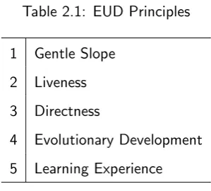
2.1 EUD Principles . . . 16
2.2 EUD Guidelines [Repenning and Ioannidou, 2006] . . . 25
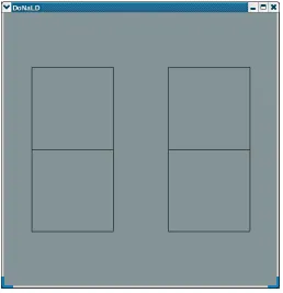
3.1 Illustrating DoNaLD to Eden translation . . . 64
3.2 20 problems of EM and its tools . . . 68
4.1 Main DOSTE event types . . . 103
7.1 CINE notation and the equivalent Eden expressions . . . 173
List of Figures
2.1 Original EM Conceptual Diagram . . . 28
2.2 Refinement from experience to “program” . . . 29
2.3 Problem Shapes . . . 30
2.4 EM ODA Framework . . . 32
2.5 Filing Cabinet and LCD Digit . . . 34
2.6 Agents interacting with a definitive script. As the script matures agent interactions are restricted. . . 34
2.7 Tkeden Input Window . . . 36
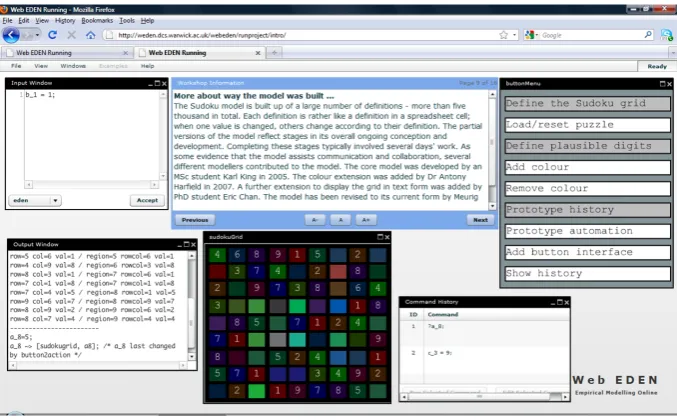
2.8 Web interface to Tkeden developed by Richard Myers . . . 36
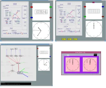
2.9 Evolution of the Digital Watch. Top-left: Cartwright 1995, Top-right: Fischer 1999, Bottom-left: Roe 2001 and Bottom-right: Cartwright’s Chess Clock 1995 . . . 39
2.10 EM Software Development Process, based upon diagram in [Beynon and Russ, 1995] . . . 42
3.1 Transition from personal to public. a) shows traditional programs that have no such on-line transition. b) gives Empirical Modellings attempt and c) shows the ideal plastic applications result. . . 47
3.2 A need to improve support for context and for construals implemented on a computer . . . 50
3.4 Notation layering in EDEN . . . 63
3.5 Fraction of student models that explicitly or implicitly mentioned prob-lems in each category . . . 67
3.6 Fraction of student models that explicitly or implicitly mentioned specific problems . . . 69
3.7 ODA with active dependency. . . 73
4.1 Cadence conceptual model . . . 77
4.2 Cadence terminology for graph structures. Dark (blue) nodes and solid lines are what the terms refer to, whilst the grey and dashed lines set the context for use of those terms. . . 79
4.3 A graph example of representing a colour . . . 80
4.4 Navigating before an assignment . . . 82
4.5 Navigation after an assignment . . . 83
4.6 Results of shallow (a) and deep (b) cloning. . . 87
4.7 A portion of the graph for integer addition. . . 89
4.8 Complete graphs showing boolean ‘and’ and ‘or’ operators in DOSTE . . 92
4.9 DOSTE definition represented as a graph structure. . . 93
4.10 Definition comparison over time. Relates to listing 4.25. . . 97
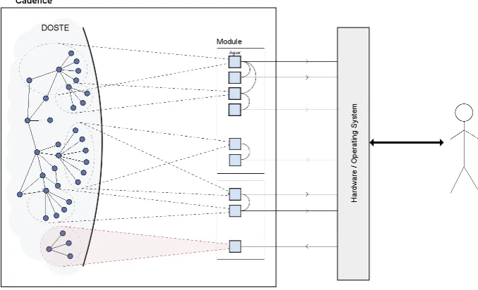
4.11 DOSTE architecture diagram showing the core components. . . 101
4.12 DOSTE Event Flow Example . . . 105
4.13 Cadence User Interface Module . . . 109
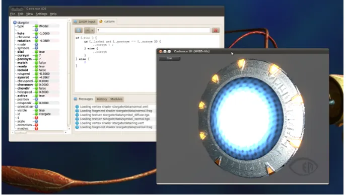
5.1 The Stargate model . . . 113
5.3 Graph structure of the Stargate model. Grey nodes indicate the existence of a C++ game library agent attached to that object. The blue node is the root node. Only structural relationships are shown, no latent or
dynamic dependencies. . . 115
5.4 Bloom configurations. Each image denotes a different configuration of the shaders that can be made while the model is active . . . 116
5.5 Stargate bloom component structural and logical dependencies . . . 117
5.6 The 9 steps of the bloom effect . . . 119
5.7 Stargate model component structure with selected dependencies shown. 123 5.8 Left: Chevron position set to 1. Middle: Chevron position set to 0. Right: Chevron on set to 1 . . . 124
5.9 Google earth running on the same video wall used for the Cadence work. Photo taken by Richard Cunningham . . . 133
5.10 Stargate model running across 3 machines using XNet module . . . 134
5.11 The Kinesin model during development . . . 136
5.12 Early version of Wii-fly game with Cadence IDE . . . 139
5.13 Cadence as a Presentation Environment . . . 140
6.1 Evolution of a Cadence model. a) shows the initially empty environment. b) observables identified. c) first dependencies introduced and agents take form. d) extensive addition of dependencies and observables with well defined agents. . . 157
7.1 An example of an automatically generated Eden observable name using the various ID components. Note that a node id and edge id are actually the same kind of id. . . 171
7.3 Bubble cells from CINE script. The last cell on the right is red. . . 177
7.4 Boolean lattice described in CINE. Left is full lattice, right is a subset of the lattice. . . 179
7.5 DMT visualisation of a CINE structure. . . 180
7.6 Dihedral group of order 8 in CINE, visualised using DMT and embeded into a presentation. . . 181
7.7 Screenshot showing EDEN running inside Cadence and communication between the two tools. . . 183
7.8 Architecture of Eden-with-Cadence hybrid. . . 184
7.9 The EDEN symbol table is mapped into the DOSTE graph to merge the two tools at the lowest level. . . 185
7.10 Oracle and Handle approach to inter-tool communication. Handles ob-serve EDEN and change DOSTE whilst Oracles obob-serve DOSTE and change EDEN. . . 185
7.11 James McHugh traffic light model . . . 189
7.12 Original Eden timetable model (Chris Keen version) . . . 192
7.13 David Evans’ Calculator Model 2011 . . . 198
7.14 Partial prototype hierarchy for the Calculator model. . . 200
Listings
3.1 Lines model observable names . . . 54
3.2 Lines model definition . . . 54
3.3 SCOUT window example . . . 65
3.4 SCOUT window translated to Eden . . . 65
4.1 DASM graph query . . . 82
4.2 DASM edge assignment . . . 82
4.3 DASM chained assignments . . . 83
4.4 DASM assignment using a path . . . 83
4.5 Incorrect assignment in DASM . . . 84
4.6 Interpreting an incorrect DASM assignment . . . 84
4.7 DASM context variables . . . 84
4.8 Node construction approach 1 . . . 85
4.9 Node construction approach 2 . . . 85
4.10 Cloning sub-graphs . . . 86
4.11 Combining graphs with union . . . 86
4.12 Shallow clone example . . . 87
4.13 Deep clone example . . . 87
4.14 DASM definition of addition . . . 90
4.15 Simple arithmetic in DASM . . . 90
4.16 Arithmetic in DASM . . . 90
4.18 DASM boolean logic . . . 91
4.19 Shortcut definition in DASM . . . 93
4.20 Definition to square a number . . . 94
4.21 Indirect cyclicity example . . . 95
4.22 If-object construct in DASM . . . 95
4.23 Syntactic sugar for conditionals . . . 96
4.24 Counting with dynamical definitions . . . 97
4.25 Semantics of definition types . . . 97
4.26 Default definition . . . 98
4.27 Generic definition to square a number . . . 99
4.28 Using the generic square . . . 99
4.29 Factorial using generic definitions . . . 99
4.30 Button centering example . . . 105
4.31 C++ agent example . . . 108
5.1 Description of a texture . . . 116
5.2 Camera motion definitions in Stargate . . . 118
5.3 Width and height scaling using dependency . . . 119
5.4 Shader variables connected by dependency . . . 120
5.5 Definitions to control blurring . . . 120
5.6 Bypassing bloom steps by changing the graph . . . 121
5.7 Stargate chevron shader variables . . . 123
5.8 Fully extending a Stargate chevron . . . 124
5.9 Retracting a Stargate chevron . . . 125
5.10 Lighting up a Stargate chevron . . . 125
5.11 Dynamical definition to rotate the dialling wheel . . . 126
5.12 Observables to check for symbol alignment . . . 127
5.13 Modified rotation condition . . . 127
5.15 Keyboard driver example . . . 131
5.16 Protein motion using dynamical definitions . . . 137
5.17 Cloning of Kinesin bond points . . . 138
5.18 Wii-remote to change slides . . . 140
5.19 Embedding Wii-fly into a slide . . . 141
6.1 Observable identification in DASM . . . 146
6.2 SCOUT window in DASM . . . 162
7.1 Cadence Notation Example. . . 171
7.2 Translation of listing 7.1 into Eden. . . 171
7.3 Cadence notation definition example. . . 173
7.4 Translation of listing 7.3 into Eden. . . 174
7.5 An if-statement in CINE showing nested queries. . . 174
7.6 Translation of listing 7.5 into Eden. . . 174
7.7 Line and box prototypes in CINE. . . 176
7.8 First cell in bubble sort array. . . 176
7.9 Second and third cells as clones. . . 177
7.10 Changing a cells colour in CINE. . . 178
7.11 Updating the Donald display. . . 178
7.12 Test binary tree in CINE (cf. figure 7.5). . . 181
7.13 EDEN handle for Cadence specified in DASM. . . 186
7.14 EDEN oracle for Cadence specified in DASM. . . 186
7.15 Eden script changing a Cadence handle. . . 187
7.16 Eden script observing a Cadence oracle. . . 187
7.17 DASM script connecting Cadence and EDEN in the Traffic model. . . . 189
7.18 EDEN agent controlling a traffic light. state1 is a handle observable for Cadence (cf. listing 7.17). . . 191
7.19 DASM context selection for cells. . . 192
7.21 Generating Donald script from Cadence oracles. . . 193
7.22 Bit inequality “function” for calculator model. . . 199
7.23 Byte comparison construct using individual bit comparisons. Input bytes are given at the top and the result is the value of b which is indivisibly calculated by dependency. . . 201
A.1 stargate.dasm . . . 216
A.2 window.dasm . . . 216
A.3 viz.dasm . . . 226
A.4 gate.dasm . . . 231
A.5 wiiflygame.dasm . . . 236
Acknowledgments
Declarations
Abstract
Creative software design, where there is no theory, no pre-computer precedent, no set of requirements or even necessarily an objective, challenges all existing software development methods. There can be no assumption that end-users know what they want. Each and every situation is unique, unpredictable and due to feedback is continu-ally changing. Fixed solutions developed by non-domain experts are all but impossible in more unconventional systems, and increasingly there may not be domain experts at all. Allowing individuals or groups of non-professionals to program is one approach (End-User Development). However, programming requires a degree of formality, design and spec-ification that cannot co-exist with the most informal pre-theoretical applications which need to be developed by exploratory experimentation to help with problem-solving and sense-making. Instead of programming a finished application from the beginning, there is a need to develop personal, provisional and subjective models and evolve these into public, objective and assured applications. Developing these models “on-line” through interactive experimentation is essential and it is the objective of Empirical Modelling (EM) research to enable the modelling of sense-making artefacts called construals.
Whilst existing EM tools are able to support construals there is a need to see how a smooth transition from construals to applications can be made. Such a migration is not one-way as the resulting applications need to remain plastic. The aim of this thesis is to explore and develop ways of enhancing EM principles and tools to better support such migrations from construals to programs.
Abbreviations
CINE Cadence in EDEN
DASM DOSTE Assembly
DMT Dependency Modelling Tool
DOSTE Definitive Object State Transition Engine
EDEN Evaluator of DEfinitive Notations
EM Empirical Modelling
EUD End-User Development
HDR High Dynamic Range
IDE Interactive Development Environment
OD-net Observable Dependency Network
ODA Observable Dependency Agency
OID Object Identifier
PSE Plastic Software Environment
AOP Agent Oriented Parser
HCI Human Computer Interaction
Chapter 1
Introduction
This thesis identifies and develops specific ways of improving Empirical Modelling tools and concepts as aplastic software environment to better support plastic applications. The terms plastic software environment (PSE) and plastic applications (plastic apps) have been introduced by this thesis to classify a certain kind of software and software environment, the definitions of which are given in this chapter in order to place the rest of the thesis in context. Empirical Modelling is an existing area of research that provides a good foundation for the support of plastic apps and will be briefly introduced here with more detail given in chapter 2. The remainder of this chapter will then discuss more specific thesis aims and questions and give an outline of each chapter.
1.1
Plastic Applications
problem through continued experimentation. At any point, even after it has solidified to a usable application, the application can be adapted and moulded into something new. This subsequent adaptation is not so plausible in traditional programs that have been developed and optimised specifically for a machine. The result of enabling plasticity is a concrete contextualised application as opposed to a generic off-the-shelf product. An additional part of this vision would be the ability to link many different plastic apps to-gether in unforeseen ways to produce an entirely plastic computing environment, perhaps even a plastic operating system1.
The concept of plastic apps comes from a collection of research areas, including end-user application development (EUD) [Lieberman et al., 2006], formerly end-user programming (EUP). Nardi gives a clear introduction in her book entitled “A Small Matter of Programming” [Nardi, 1993] as to why end-user programming is vital. More recent work by others discusses how, in specific cases such as with spreadsheets, it has proven remarkably successful [Burnett, 2009]. One such argument given by Nardi is that end users “have the detailed task knowledge necessary for creating the knowledge-rich applications they want” (p.xi) and that “the process of transferring domain knowledge to a programmer... is inefficient” (p.123). Perhaps, however, we are dealing with end-users who do not have a detailed task knowledge but who might be attempting to understand a particular solution to a problem whilst they are developing the application? In which case EUD is also a learning experience [Repenning and Ioannidou, 2006]. A claim made by Nardi that I strongly agree with, and which is still valid today, is that “we have only scratched the surface of what would be possible if end users could freely program their own applications” [Nardi, 1993, 3].
EUD has been defined as “a set of methods, techniques, and tools that allow users of software systems, who are acting as non-professional software developers, at some point to create, modify, or extend a software artefact” [Lieberman et al., 2006]. It has been claimed by some that EUP and perhaps EUD has succeeded [Burnett, 2009]
1Operating systems may already be considered as plastic, but not to the degree being proposed in
as we now have spreadsheets, web authoring tools, graphical languages and various educational tools. To a degree this is true - there are now over 50 million end-user pro-grammers who adapt or create software in some form. However, is the software they are creating or adapting really that plastic? Certainly as an everyday user I am not often able to adapt software to my personal needs except in the most specific and pre-defined ways such as with e-mail filters or user interface customisation, or by learning how to program and write custom extensions. The problem seems to be that EUD systems in practice are typically domain restricted or only support a tiny amount of end-user adaptation of existing environments [Repenning and Ioannidou, 2006]. What is needed then is an environment which supports the extreme notion ofplastic applications which is not, as a system, domain specific and not restricted to specific developer chosen adaptations. EUD needs to be broadened beyond adaptation of existing environments. There have been attempts to do this in the EUD community [Burnett et al., 2001][Repenning et al., 2000] but such research has not gained widespread recognition in the software industry as a whole [Fischer, 2009]. More will be said on these tools and others in chapter 2.
Other researchers in the Human Computer Interaction (HCI) and software de-velopment communities have adopted terms such as “software plasticity” to describe the degree to which an interactive piece of software can adapt to changing contexts of use [Calvary et al., 2004][Morris, 2005][Sendn et al., 2005], although this is often in a developer focused context rather than that of an end-user. There is also now widespread use of technologies whose purpose is to increase flexibility to better deal with change, including Service-Oriented Architectures [Erl, 2005], Aspect-Oriented Pro-gramming [Kiczales et al., 1997] and Agile methodologies [Dingsyr et al., 2010], all of which have the potential to radically improve end-user application development but currently, for the most part, remain in the domain of professional software developers. There are a lot of technologies out there which could help enable plastic applications but that have yet to be used in this way.
ap-plications concept is that of Empirical Modelling (EM) at the University of Warwick [EM Website]2. The Empirical Modelling group have been exploring informal modelling tools and principles which enable users to develop models without needing to be expert pro-grammers, or experts in the model’s domain. A key aim of Empirical Modelling is to allow users to develop models informally without specification or design so that they may gain understanding of a problem they know little about prior to the modelling activity [Milner, 1986][Beynon and Russ, 2006]. EM is a conceptual framework for end-user development but rather than looking at ways of adapting traditional applications it has taken the more radical step of rethinking programming [Beynon et al., 2006a] and software from the ground up. The ideas and tools behind EM provide a great deal of insight into possible ways of implementing the EUD vision and the vision of supporting plastic applications. There are already several example EM models [EM Website], devel-oped using existing tools [Ward, 2004, p.194], which illustrate the plastic app concept, including one model for timetabling which has been used as an application by staff at the University of Warwick [Beynon et al., 2000b]. The EM concepts and tools, however, have not yet been able to support the development of fully-fledged applications from models, in part because of the EM research objectives not being aligned with those of EUD but focused more on personal and individual modelling activities, and in part due to inadequacies of the tools.
1.2
Plastic Software Environments
Aplastic software environment (PSE) is defined here to be, as the name suggests, an environment that hosts and enables the continuous development of one or more plastic applications. Such an environment may just be a form of modelling tool or virtual machine but could be an entire operating system hosting many different but connected plastic applications. The principles and concepts behind a PSE will be discussed further in section 2.1.1 which identifies key EUD principles and also towards the end of this
2
work in 6.1. Some PSE characteristics, however, include:
• supporting the reversable refinement of an application.
• using a single conceptual model allowing gentle-slope development.
• not being brittle in the presence of the unexpected.
• being live and interactive for immediate feedback.
• not requiring initially undesirable precision and formality.
Whilst there are many examples of environments and applications that support end-user development to some degree, for example GIMP, Kate and Google-Mail (with their supporting technologies), there are few that would be considered a PSE. Examples of a PSE are hard to find but include spreadsheet environments, Forms/3 [Burnett et al., 2001] and AgentSheets [Repenning et al., 2000] along with the EM tool Eden [Ward, 2004, p.194]. With regards to spreadsheets, plastic applications would be models that have been sufficiently developed to become useful applications, perhaps for financial modelling or a teacher developed model for a school sports day. In these examples the model may well be used as an application but is always open to modification to adapt, extend or fix at any time.
Apart from perhaps spreadsheets, plastic software environments are far from ubiquitous. With the enormous success of the spreadsheet it seems most surprising that EUD environments have not become increasingly powerful and available even though, in general, software is now moving towards EUD. Perhaps the reason is the lack of research into the principles and conceptual frameworks for them?3 The key players should be the operating systems developers and communities since a plastic operating system4 would be a “dream come true”.
3Of course it is also necessary for such software to be marketed. 4
1.3
A Lack of Plasticity
In order to achieve the level of flexibility (or plasticity) desired for plastic apps there is a need to look more closely at why existing systems are not capable of providing it, ignoring for the moment the environments developed by the EUD community (discussed in chapter 2). To aid this discussion let us use an analogy of developing a recipe for making a cup of tea. It is relatively easy to provide a generic recipe for making tea that is along the lines of: fill kettle with water, turn kettle on, get tea bags and mugs, pour boiling water from kettle into mugs, add tea bag to mug, remove tea bag, add milk and so on. Such a program could be parameterised by the developers to allow the user to control, for example, how long to leave a tea bag in the water, how much milk to use, how many mugs, how much water and so on. What if, however, the person making the tea was in an unfamiliar house and did not know where to find the tea or there is no kettle and so a sauce pan is needed instead?
One of the problems is that programs are based upon brittle assumptions. David King, in his thesis on “Parting Software and Program Design” [King, 2005], states that “the assumptions underlying programs are always brittle” (p.10) because “program descriptions must ... be both closed and complete” (p.14). Whilst “brittle assumptions [are] strong when true, but useless when false” (p.10) it is unfortunate that ‘almost every ’interesting’ system is incomplete” (p.14) meaning that these assumptions are likely to fail to hold. From the analogy, the program for making tea makes assumptions about knowing where to find tea bags and about the existence of a kettle. It is conceivable that the developers of the program foresaw this and provided the option of using a saucepan, but what if they did not? At this point, in a traditional application, the developers would need to alter the requirements specification, design and implementation of the program to allow for saucepans.
a set of associated laws of software evolution which state that change is inevitable in certain kinds of applications and results in the need for an iterative approach to software development. One of the more significant laws, in my opinion, is that of feedback where the introduction of a piece of software will, by its very existence, change the nature of the problem [Lehman, 1996]. The consequence of this feedback is that it becomes impossible to predict in advance the requirements and design of an application [Fis-cher, 2009]. Since Lehman first studied the concept of software evolution there has been a great deal of research into software evolution, including empirical studies and the development of tools and techniques for dealing with evolving programs. The soft-ware industry has also recognised the problem of changing requirements, which has led to the development of technologies such as the recent Service-Oriented Architectures approach, Aspect-Oriented Programming and other kinds of Object-Oriented Program-ming, along with Agile methodologies to rapidly implement these changes. All of these new technologies and methodologies are there to reduce the difficulty and increase the speed with which changes can be implemented by developers. All of these technologies and methodologies are there to alleviate the problems associated with having brittle assumptions, the result of needing to use traditional programs.
rethink about the nature of programming itself. The EUP community have realised this and it is partly why EUP became End-User Development. The notion of evolution and experimentation came in and the whole development process, not just the programming, came under scrutiny.
The notion of software as being engineered is often misconceived by traditional computer science [Jackson, 2005]. Software engineering focuses on theory and formal-ity through specifications of requirements using mathematical abstractions. Whilst for some applications this is an appropriate strategy, for many existing applications and for many that have yet to be conceived it is wholly inappropriate to think that they could be engineered in this way. Engineering practice is about the design and construction of an artefact [Rogers, 1983] which transforms the physical world, rather than focussing on the machine world. As Jackson puts it, requirements and specifications “are all to be understood in terms of physical phenomena rather than in terms of purely mathemat-ical abstractions ... [any] abstractions must be firmly grounded in observable physmathemat-ical reality” [Jackson, 2005]. As Lehman’s laws indicate, change is inevitable and potentially rapid in the software world. With software we are also dealing with the unknown where there is sometimes no pre-computer precedent and where the consequences cannot be foreseen. Such applications cannot be formally engineered but must be explored and evolved by experiment to first gain understanding, more akin to the real practice of engineering. Despite this realisation by many (especially in the EUD community) the idea of formal design and specification remains entrenched.
stages were fully intertwined so that the idea of needing to develop programs separately as an additional step were to be removed then the problem of brittle assumptions would also be removed. Applications evolve out of models without any separate translation into a program, this is what the concept of plastic applications is about. A suggestion made by King is that instead of attempting to reduce complexity there need to be tools which better enable us to deal with that complexity. Perhaps we need plastic software environments which appropriately manage complexity whilst being end-user friendly and supporting the experimental evolution of a model from the ground up until it becomes a plastic application, an application that is not made brittle by its translation into a traditional optimised program.
1.4
Thesis Aims
The higher aim behind this work is to answer the question of how to bring extreme plasticity to software in a way amenable to everyday users. One of the difficulties in bringing this about is the lack of suitable plastic software environments in which such an activity of moulding software can take place. There are many applications that provide possible examples of a plastic or semi-plastic environment but most are domain-restricted. One of the most promising but underdeveloped approaches is that of Empirical Modelling (EM). In addition to a lack of tool support for plastic applications there is also a lack of principles and of a conceptual framework for such an activity. Empirical Modelling may also provide a basis for such a framework. So my research question is:
How to adapt, in specific and selective ways, Empirical Modelling concepts and tools to enable a migration from informal models to programs by end-users as an attempt at supporting the creation of plastic applications?
a fully-fledged plastic software environment to be used in real situations. This work explores these issues and proposes possible solutions in the form of a new tool and re-conceptualisation of the principles. An additional aim that is being kept in mind (but not a key focus) throughout the work is the possibility of developing a plastic operating system, which will influence the design of the new tool to some degree. Specific objectives include:
• Critiquing of Empirical Modelling (and to a lesser degree EUD) to identify specific areas of improvement and ways that these improvements can be achieved by the development of a new tool.
• Developing a new prototype tool for Empirical Modelling and EUD which attempts to implement solutions to the specific identified problems.
• Creating models and examples within the new prototype environment to demon-strate it as an EM EUD tool and to demondemon-strate the new features it provides.
• Analysing the work to identify key principles and concepts behind the new
en-vironment to develop a framework which can help support the notion of plastic applications.
1.5
Thesis Outline
The thesis has been organised into 8 chapters which are as follows:
Chapter 3 explores specific problems with existing approaches in achieving the kind of plasticity being sought after. Primarily the focus is on Empirical Modelling (EM) tools and concepts, where a critique is given, as these are already a close match to a plastic software environment. The problems with EM are then critiqued with reference to the solutions from industry and EUD that appeared in the background material of chapter 2. At the end of the chapter specific research questions are posed and a form of specification is given for a new prototype environment called Cadence.
Chapter 4 forms a central part of this thesis. It documents the development of Cadence, proposed in chapter 3. The architecture and interfaces for Cadence are given, along with some examples of how Cadence is to be used.
Chapter 5 discusses various example models that were developed within Cadence in detail. These models include games, presentation environments and biological models. The examples show the flexibility and other characteristics of the tool which are relevant to both the problems identified in chapter 3 as well as the broader objectives of the thesis. Each model has been used to illustrate how the Cadence tool has resolved specific issues.
Chapter 6 identifies key principles and concepts from the prototype to develop an idealisation of Cadence. These principles have come from the work in chapters 3,4 and 5 and provide a possible framework for plastic software environments generally. It is this chapter that contains the second major contribution of this thesis.
Chapter 7 looks at the impact of the Cadence tool and the principles of chap-ter 6 upon Empirical Modelling. Hybrid tools are discussed which attempt to resolve limitations in both Cadence and existing EM tools, as well as provide a clear means of comparison. Example models are also included that were developed by students of Em-pirical Modelling who used either Cadence or a hybrid for their projects and coursework.
Chapter 2
Background
The previous chapter introduced two key areas that are the focus of this work: End-User Development and Empirical Modelling. As the aim is to develop new tools and principles it is important that the existing tools and principles of both areas are understood since they provide the foundation for this work. To that end this chapter will begin by giving a brief summary of key EUD principles, guidelines and relevant existing tools, followed by a similar summary of EM principles and tools.
2.1
End-User Development
end-users, especially those at home making personal use of a computer, are still struggling with EUD and hence the focus of this work being to broaden the scope of EUD beyond professionals and education.
As this work is looking at how to merge EUD concepts and Empirical Modelling concepts to produce a plastic environment, the grander issues of design and testing in larger projects are going to be put aside. The focus for this work will remain on the principles and guidelines of EUD and end-user programming, along with the technologies that exist which enable EUD, to see how these can be applied to EM or how EM already uses them.
2.1.1 Principles
There are a collection of key principles that can be found across the EUD literature which are important for enabling end-users to adapt and develop their own systems. The principles give a vague indication of a framework for EUD, although this remains rather loose and poorly formulated. One attempt at developing such a framework is that of meta-design by Fischer [Fischer, 2000][Fischer and Giaccardi, 2006][Fischer, 2009]. The most significant and relevant principles are given below.
slope than traditional programming, they are far from a smooth slope and each requires different skills that need to be learned. The more adaptation mechanisms involved the more gentle and smooth the slope of complexity will be, but it is vital that the principles underlying all these mechanisms are related so that there can be an elegant transition which builds upon the previous [Spahn et al., 2008].
• Liveness: Also known as live editing [Smith et al., 1995] where changes can be made to a live system without needing to restart the application [Lieberman et al., 2006; Tanimoto, 1990]. This enables users to see and directly experience the consequences of any changes with immediate feedback [Burnett et al., 2001] and allows those changes to be of an incremental nature. It is one of the key characteristics of spreadsheets that has made them so successful [Nardi, 1993, p.88]. In order to achieve live editing a certain degree of robustness is required along with the ability to undo mistakes. It also goes hand-in-hand with thegentle slope principle since not allowing for live editing will certainly introduce barriers for the user.
• Directness: by reducing the conceptual distance between the problem domain and software environment the user can more easily identify and resolve their problems by making appropriate changes [Pane and Myers, 2006]. Directness comes from the HCI concept of direct manipulation which attempts to make user interfaces easier to use and is related also to the gulfs of execution and evaluation [Norman, 1998]. It has not been a consideration in the design of most programming lan-guages so the programming world and problem world remain distanced which hin-ders the problem solving process [Pane and Myers, 2006; Green and Petre, 1996]1. It is a vital principle in EUD and can take various forms including task-specific languages [Nardi, 1993, p.37] or concrete and directly manipulable objects [Smith et al., 1995].
1
Table 2.1: EUD Principles
1 Gentle Slope 2 Liveness 3 Directness
4 Evolutionary Development 5 Learning Experience
• Evolutionary Development: sometimes this is described as design-during-use or
design for change [Dittrich et al., 2006][Fischer and Giaccardi, 2006]. Evolution is at the heart of EUD and is the driving factor behind it. Things are always changing, either because the environment is changing or because the focus is changing [Lehman, 1980][Fischer, 2009]. Not only is there change but often it is not possible to adequately identify all requirements to design a piece of software in advance [Swartout and Balzer, 1982], especially in EUD where in the most extreme cases there are no requirements since it becomes an experimental hobbyist activity [Ko et al., 2011]. As a consequence evolution must be supported in software applications and allowing end-users to customise and extend programs is an efficient way to achieve this [Nardi, 1993, p.3].
• Learning Experience: the whole process of EUD can be framed as a learning
2.1.2 Common Approaches
The technologies used for enabling EUD typically fall into one of the five categories which are listed below [Spahn et al., 2008]. It is significant that these approaches are either exceptionally simple but restricted to what the developer anticipated, or involve some form of simplified programming. Despite “gentle-slope” being a key principle it seems there is still a gap between parameterisation and programming. For the most part the simplified programming approaches are also domain-specific and there is yet another gap between them and more sophisticated scripting and programming languages. The bridge between interface customisation and classical programming is rather weak.
• Interface Customisation
• Application Parameterisation
• Programming-by-Demonstration
• Visual Programming
• Natural Language Programming
2.1.3 Existing Environments
Both within the EUD community and outside it there are many examples of adapt-able applications making use of the principles and approaches identified above. These applications include GIMP2, Kate, Firefox, Gmail and many more with most modern applications supporting some level of EUD. Whilst there have been interesting recent developments, such as Service-Oriented Architectures [Erl, 2005] (specifically web ser-vices) and the associated end-user developed web mash-ups, for this work of bringing EM into the EUD picture the focus will remain with the major and classic EUD environ-ments and languages. Three of these environenviron-ments have been identified as key players 2GIMP allows for extensive interface customisation, provides many parameters to control the
and are of specific interest due to some close connections with Empirical Modelling ideas: Forms/3 [Burnett et al., 2001], Self [Ungar and Smith, 1987] and Subtext [Ed-wards, 2005]. Other environments which have had some influence on the work include: AgentSheets [Repenning et al., 2000], HANDS [Pane and Myers, 2006], Croquet (now called Open Cobalt), Plan 9 [Pike et al., 1995], Singularity [Hunt and Larus, 2004] and EROS [Miller et al., 2003].
As a research language that is based upon the spreadsheet paradigm, Forms/3 attempts to remove some of the limitations encountered with other similar spreadsheet languages. The spreadsheet paradigm and associated languages are defined by Alan Kay’s value rule [Kay, 1984] where a cell’s value is defined solely by its formula. Ac-cording to [Burnett et al., 2001] spreadsheets suffered from two limitations: first is the lack of support for different types and the second is the lack of abstraction mechanisms. It was the goal of Forms/3 to remove these limitations whilst remaining faithful to the value rule and also to the EUD and HCI principles already identified (gentle slope, liveness and directness).
In order to achieve its goals Forms/3 made two basic changes to the standard spreadsheet along with three major additions. The two basic changes are:
1. Removing the grid. Instead of forcing a grid layout onto cells it is possible to position the cells anywhere on the form (aka. worksheet). This enables additional flexibility in visualising results.
2. Giving cells names. Since there is no grid, cells can be given names to identify them.
The three major additions, which provide insight into ways of enhancing Empir-ical Modelling tools3, are:
1. Graphical and user-defined types. Cell values may be a graphical type instead of being restricted to numbers and strings as is usually the case in spreadsheets. This 3Empirical Modelling tools are also based upon spreadsheet concepts so these enhancements are
allows for graphics without requiring features outside of the spreadsheet paradigm (breaking thevalue rule).
2. Dynamic Grids. The size of the grid may vary automatically and it is possible to give formula to a region without manual copy/paste actions.
3. Temporal streams of cell values. This allows for change over time and hence animation as well as “time travel”.
User-defined types are supported in Forms/3 by the use oftype definition forms4. A type is a collection of cells (or cell groups) which can internally reference each other. When a type is instantiated these internal cells may be connected to other cells by a formula reference. Whilst Forms/3 does provide these visual type definition forms and direct manipulation capabilities for creating types, it is all still describable as a textual cell formula and so still follows the value rule of a spreadsheet. By sticking with the use of forms, cells and formula for describing types the end-user is not burdened with new concepts such as classes. More recently the Forms/3 type system was extended to include support for inheritance, called similarity inheritance [Djang and Burnett, 1998][Djang et al., 2000].
The dynamic grids supported by Forms/3 are similar to traditional matrices and spreadsheet grids, only they are not statically determined. An important feature of these dynamic grids is the ability to specify a formula over a contiguous region (or the whole grid), which removes the formula replication task of the user but also allows for arbitrarily large grids with formulas as they are created in a lazy manner. These dynamic grids offer the same functionality as lists in functional languages since Forms/3 does support recursion. However, when used in combination with the time-varying properties of Forms/3 it has been found that both recursion and iteration are not required and that this improves directness and concreteness which helps with EUD [Burnett et al., 2001].
4Also called Visual Abstract Data Type (VADT) forms and are discussed in more depth in [Djang
Cells in Forms/3 do not just have a single value but consist of a temporal vector which records all the values it has ever had along with the times at which it had those values. With this it is possible for cells to refer not only to current values but to past values and hence enables animation to take place by a cell referring to its own past. Another interesting consequence is that “time travel” is possible where the entire system is reverted to a previous state or where changes to the past can be made with the consequences propagated immediately to give immediate feedback, something which has been called steering [Burnett et al., 2001]. It is the liveness of the system which allows for steering whilst keeping the system consistent.
A language which provides further insight into the issue of user-defined types and for providing structure in an end-user friendly way is Self [Ungar and Smith, 1987]. The motivations for developing Self are given in [Smith et al., 1995] where the authors say that:
Programmers are human beings... they also need things like confidence, comfort and satisfaction – aspects of experience which are beyond the do-main of pure logic.
an important concept in the development of Forms/3.5 It is interesting how the type definition forms in Forms/3 seem to be a hybrid concept between class and prototype since these forms are used like a class but can be copied like a prototype [Burnett et al., 2001].
Five key reasons are given in [Ungar and Smith, 1987] for using prototypes instead of classes, these are as follows:
1. Simpler relationships with only a single “inherits from” concept which allows for simpler inheritance hierarchies.
2. Creating by copying where copying is a simpler metaphor than instantiation.
3. Examples of pre-existing modules, allowing a user to examine a typical represen-tative as opposed to attempting to make sense out of a description.
4. Support for one-of-a-kind objects which allows individual objects to be customised directly and independently.
5. Elimination of meta-regress which is a conceptually infinite problem where a class is an instance of a meta-class and so on.
Something considered an important characteristic of Self is its support for live editing, an important EUD principle. According to the authors Self provides “an un-usually direct interface to such live changes” [Smith et al., 1995], in part due to the close match and integration between the language and the environments user interface called Morphic [Maloney, 2000]. The directness and liveness of Self depends not only on the purity of the object-oriented language but also on the direct manipulation capabili-ties of Morphic and itsmeta-menu to make live changes, which creates an “experience of programming that can be learned more easily [by end-users]” [Smith et al., 1995]. Themeta-menu is available for all graphical objects, calledmorphs, which allows those 5“Immediate feedback is facilitated when concrete objects are present in the programming
objects to be changed. The meta-menu also provides an outliner menu item to show and edit language properties of the object such as slots which include methods and properties.
Not only is Self one of the first and most significant prototype-based languages to focus on the user’s experience, but it was also the first interactive pure object-oriented language to have good performance and good responsiveness [H¨olzle and Ungar, 1994]. Some of its optimisation strategies have gone on to be used in more well known languages such as Java. What this has done is show that end-user friendly languages do work sufficiently well for real applications.
The final system to be looked at here is Subtext developed by Jonathan Edwards at MIT [Edwards, 2005] and its more recent incarnation Coherence [Edwards, 2009]. Subtext has much in common with both Self and Forms/3, both of which influenced its development. It has spreadsheet like formula characteristics as well as prototype-based cloning as a core concept. Edwards is attempting to “transcend paper-centric programming” and reduce Norman’s gulfs of execution and evaluation [Norman, 1998] by making the representation of a program the same as its execution6. This involves moving away from just text but at the same time not taking the usual visual programming approaches which have a tendency not to scale well and, according to Edwards, are still
paper-centric.
With Subtext the programmer is working directly with a tree structure that is both the code and the data, using a suitable graphical interface. Nodes form structures and at the leaves there can either be an empty structure called an “atomic value” or a reference which is much like a spreadsheet formula that returns a node (which may be an “atomic value”). Functions are “structures that react to change” [Edwards, 2005] and use the exact same principle as Core Forms/3 [Djang et al., 2000] where there is a structure with subnodes (cells in Core Forms/3) for the parameters and another subnode for the result with a formula in the result that describes the function. Spreadsheet-like
6This similarity of representation in Subtext relates well to the notion ofcomputation by navigation
dependency maintenance is then used to give immediate feedback in response to any change and so Subtext supports the EUD liveness principle.
In some respects, therefore, Subtext is a prototype-based environment that has not embraced the object-oriented paradigm. It is not based on message passing nor does it have imperative methods. Whereas OO merges state and behaviour and Self in particular focuses almost entirely on behaviour, Subtext has achieved the opposite by focusing entirely on state with all behaviour actually being a form of state maintenance. Even function calls are done by copying. In summary then, Subtext is making use of the prototype-based approach to achieve a form of programming that involves direct manipulation rather than indirect textual manipulation. It is perhaps closer to Empirical Modelling than the object-oriented Self language is due to its focus on state.
Edwards has since gone on to develop a new language called Coherence which is based on his concept of coherent reaction [Edwards, 2009] that is much more dependency-like than Subtext. Unfortunately he has recently discovered that his approach is non-deterministic so has abandoned that project (attempting to make it non-deterministic by moving away from dynamic prototypes to static classes instead) [Edwards, 2010]. De-spite this it will be discussed here as an example of a prototype-based and dependency-based language combined.
or, as Edwards states, it is actually a problem of constraint discovery [Edwards, 2009]. Coherent reaction then was an attempt at performing constraint discovery without either reducing the expressive power of the language or involving the programmer. Edwards’ higher goal was to deal with the problem of imperative programming where it is up to the programmer to orchestrate the exact order in which all events takes place. It is significant that he chose both the prototype-based and spreadsheet style approaches to achieve this and his justification is given with an example demonstrating the difficulties of execution order in imperative languages. It comes back to ultimately attempting to build a model of coherent state that can deal with change rather than focusing on behaviour.
2.1.4 Guidelines
From their work on AgentSheets, an EUD environment, Repenning and Ioannidou iden-tified thirteen design guidelines for end-user development environments [Repenning and Ioannidou, 2006]. All of these guidelines are, to varying degrees, applicable to a plastic software environment and so will be utilised in the design and development of the new tool. Table 2.2 shows these guidelines.
1 Make syntactic errors hard 2 Make syntactic errors impossible 3 Use objects as language elements
4 Make domain-oriented languages for specific EUD
5 Introduce Meta-Domain orientation to deal with general EUD 6 Support incremental development
7 Facilitate decomposable test units
8 Provide multiple views with incremental disclosure 9 Integrate development tool with web services 10 Encourage syntonicity
11 Allow Immersion 12 Scaffold typical designs 13 Build community tools
2.2
Empirical Modelling
The Empirical Modelling (EM) research group is a small group of researchers and stu-dents based at the University of Warwick in the UK [EM Website]. The aim of the group is to explore and develop a conceptual framework and associated tools for infor-mal modelling activities that are grounded in experience. Over the years a considerable number of these models have been developed with their tools by various undergradu-ate and postgraduundergradu-ate students at Warwick [EM Projects]. Their tools have often been used for educational purposes [Harfield, 2008], learning about problems [Care, 2006] and computing [Beynon et al., 2000a]. This section will cover the key concepts of EM, the existing tools and some example models and application areas. The conceptual frame-work and some of the concepts used in their tools provide an excellent foundation for plastic applications.
2.2.1 What is Empirical Modelling?
The word empirical should be well understood as meaning “derived from experience and experiment” and gives a clue to what Empirical Modelling is about. EM takes this notion of experience and experiment right to the core of its conceptual framework to describe a new modelling approach based “firmly on direct,living experience rather than formal representations” [Beynon, 2011, p.1]. It is argued that experience is primary and comes before any theory and formal representations can be developed, relating strongly to William James’ notion ofradical empiricism[James, 1912/1996; Beynon, 2007] where to know something is to experience an association between one aspect of our experience and another.
worlds. Beynon and Russ discuss these two factors in [Beynon and Russ, 1992] where he says that “an adequate theory of computation must allow a high degree of interaction between these two factors”. It is noted by Beynon and Smith that computer science only talks about the first factor and that “curiously” the semantics of a program do not consider the second factor, that of interpretation. The consequences of this lack of concern for the second factor are eloquently put by Black:
“the drastic simplifications demanded of success of the mathematical analy-sis entail serious risk of confusing accuracy of the mathematics with strength of empirical verification in the original field”[Black, 1962] as cited in [Beynon, 2011]
Focusing only on the abstract mathematical world and ignoring the concrete reality we inhabit will likely mean that any model, program or theory developed in such a way will be suspect when it comes to being interpreted. In practice the concrete is not ignored:
“In devising a mathematical model of a tree, the mathematician adopts a constrained way of observing features relevant to a functional objective but may first need to identify suitable features and patterns of behaviour derived from exploratory experiment”[Beynon, 2011, p.5]
If the word “mathematical” is replaced with “computer” and “mathematician” with “programmer” then the above statement by Beynon accurately describes the need for a software development process with requirements (a functional objective) that need to first be formulated. Exploratory experimentation is a term used by Steinle for ex-perimentation that takes place before any well formulated theory exists, in contrast to experimentation that is “theory-driven” [Steinle, 1997].
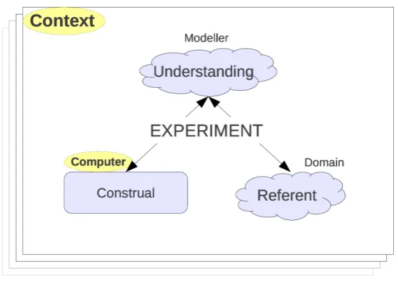
Figure 2.1: Original EM Conceptual Diagram
to find out proper concepts and classifications by means of which those regularities can be formulated.” [Steinle, 1997]
Exploratory experiments can be found throughout the scientific community, with a well documented and interesting example being the experiments done by Faraday in trying to develop a theory of electromagnetism. Gooding provides an account of Faraday’s work which attempts to discover how Faraday was able to gain important understanding through the use of physical, metaphorical models of otherwise invisible forces [Gooding, 1990]. Faraday uses exploratory experimentation to eventually develop a theory. It is clear from this, as well as from Black’s comment, that everything is, and should be first and foremost, grounded in experience. This is certainly the tenet of Empirical Modelling which has borrowed ideas such as that ofconstrual7 from Gooding’s
work on Faraday.
So Empirical Modelling is attempting to develop a framework for pre-theory exploratory modelling which enables the modeller to identify “empirical regularities” and gain sufficient understanding to construct a formal account. Experiment is to be used to 7A construal is a provisional, personal sense-making entity [Beynon, 2011, p.1] and originated in the
Figure 2.2: Refinement from experience to “program”
bridge the gap between immediately experienced and circumscribed behaviour [Beynon, 1994]. Figure 2.1 shows how this has been conceptualised as a process involving four components which co-evolve in a live fashion to construct and refine models whilst allowing the modeller to gain understanding [Beynon, 2011].
The diagram in figure 2.2 is intended to illustrate how, in EM, an artefact is re-fined from being initially an open-ended experience to being a “program” with restricted interpretations andritualised interactions8. The curve shows, in a much simplified way, the boundaries of what the modeller considers as meaningful interactions and interpre-tations at a particular stage of refinement. As the artefact becomes increasingly refined (moving up the y-axis) through a process of exploratory experimentation the range of possible interactions and interpretations becomes increasingly restricted, shown by a,b and c. Of course, the process is considerably richer than indicated in figure 2.2.
“the model migrates... from provisional to assured, subjective to objective, specific to generic, personal to public. To support this migration, the model has to be fashioned, via interactions both initiated and automated, so that
8
Figure 2.3: Problem Shapes
the views of many agents - human and non-human - are taken into con-sideration. This process of construction is in general open-ended and never absolutely resolved.”[Beynon, 2011, p.17]
An analogy of devising a walk has been used in [Pope and Beynon, 2010b] to explain the evolution of an EM artefact. Initially any walk plan is entirely unformed and the possibilities are almost unrestricted, which corresponds to being at the experience level in figure 2.2. Gradually the walk planner will decide on a region and then maybe a specific mountain to walk on. This is a refinement which moves up the diagram to perhaps be considered aconstrual or “model”. The process continues until the planner has a precise set of instructions for paths to follow and this would be at the level of refinement expected of the “program” level. What this analogy shows is how initially any plan is provisional, subjective and personal but will be refined by an exploratory process until it is assured, objective and public. The walk plan is initially at the mercy of the planner’s imagination (within certain limits) but eventually becomes something which can be described to others and followed in an objective fashion.
it is possible to refine an artefact to a point and get “stuck”, requiring a degree of backtracking to a previous and less refined state in order to explore and experiment a different way. Finally, c) shows a scenario where refining to an assured, objective and public artefact may not be desirable. What is important then is for an ability to move smoothly from construal to model to program and back again. The categories of construal, model and program are blurred concepts attempting to name specific stages of a continuous process.
An important note to make is that the terms “program” and “model” as used in figure 2.2 are not identical to the traditional concept of program and model. A traditional program will typically have fixed functionality to enable optimisation, whereas the EM “program” still has a flexible functionality (possibly at the expense of not being optimised). Unfortunately perhaps, computer science and the software industry have widely assumed that problems must be abstracted before they can be solved, with increasing layers of abstraction being the solution to complexity. Computer Science has stuck with the first factor, ignoring the second and so results in inflexible programs.
“Whereas conventional modelling uses abstraction to simplify complex phe-nomena, EM generates an interactive environment in which to explore the full range of rich meanings and possible interpretations that surround a spe-cific ... phenomenon”[Beynon, 2011, p.3]
Figure 2.4: EM ODA Framework
2.2.2 The Principles
One of the key objectives of EM is to provide a solid conceptual framework and philosoph-ical account of this kind of exploratory, experiential modelling activity on a computer. An experiment involves the observation of and interaction with state and so Empirical Modelling principles are “fundamentally concerned with modelling state” [Harfield, 2008, p.31]. Since the state being modelled is “empirically apprehended” and is somewhat different to traditional program state, it has been called state-as-experienced [King, 2004, p.30]. In addition to modelling state the notion of agency, the observation and interaction, needs to also be considered and so becomes the second central concept.
The construction of artefacts that relate tostate-as-experiencedin the referent is the process being described by figure 2.1. In the diagram there is only a single modeller involved, but there is little reason not to consider multiple human agents being involved and work to that effect can be found in [Sun, 1999; Chan, 2009; Beynon and Chan, 2006].
The concept of state-as-experienced can be split into two: observables and dependencies. The motivation for this split lies in the fact that we not only observe quantities or qualities of experience but also the associated relationships between them. Therefore there are three core concepts in Empirical Modelling which are well expressed in [King, 2004]:
ascribed”. There are no restrictions on what this might be and certainly does not need to be numerical. It is not a mathematical variable due to its concrete nature, but may have some connection to variables in traditional programming languages.
• Dependency: “a relationship between observables such that interaction with one
observable leads indivisibly in our experience to a change in the other”. These relationships are what allow changes to propagate and crucially are what enable experimentation to occur. They are the “experientially-mediated” associations which, from radical empiricism [James, 1912/1996], provide meaning.
• Agency: “an agent is projected on to the referent as something that can change the
state of the model in some way by manipulating observables and the relationships between them”. Each agent may have a different view and interpretation of the model of state. Agents may be human or non-human, there may be one or many and they may also act concurrently [Beynon, 1997a].
Figure 2.5: Filing Cabinet and LCD Digit
State-as-experienced (observables and dependencies) is embodied in a defini-tive script, a concept that has been with Empirical Modelling since Yung developed EDEN [Yung, 1990] and which has been explored in depth in [Rungrattanaubol, 2002]. All interaction with the model is conceived as making redefinitions in the script. A definitive script may consist of a collection of scripts, each of which may use a different
definitive notation9 that is task-specific. Figure 2.6 shows how agents interact with scripts and that over time these interactions becomeritualised and restricted.
2.2.3 Current Tools
Whilst EM is primarily a conceptual framework there has been considerable tool develop-ment to support such a modelling activity on a computer. The only Empirical Modelling tool currently in use is Tkeden, originally called EDEN10 by Edward Yung who first developed it [Yung, 1990]. EDEN was intended to be a “general-purpose language sup-porting definitions” [Yung, 1990, p.6] which borrowed much from spreadsheets and C. It is useful to note that EDEN was developed around the same time as both Self and Forms/3 discussed previously. Since its inception, EDEN has been extended by many developers and used by hundreds of students and academics [EM Projects]. Ashley Ward gives a detailed up-to-date picture of the EDEN tool in chapter 4 of [Ward, 2004].
Additional tools have been explored, including the Abstract Definitive Machine (ADM) by Mike Slade [Slade, 1990], Definitive Assembly Maintainer (DAM) by Richard Cartwright [Cartwright, 1999] (along with a Java version called JaM and subsequently JaM2) and finally the Definitive Object State Transition Engine (DOSTE) [Pope, 2007] which was developed by myself as Empirical Modelling coursework. The original DOSTE is not the same as the work given in this thesis but was the origin of some of the concepts. Again, these tools (except DOSTE) have been reviewed in detail by Ward in [Ward, 2004].
9Adefinitive notationcalled ARCA was the origin of Empirical Modelling [Beynon, 1985] and so this
concept has been involved since the beginning. It is intended to be a specific algebra for a particular set of problems, in this case Cayley Diagrams.
10
Figure 2.7: Tkeden Input Window
[image:57.595.151.490.427.637.2]For the purposes of brevity only the EDEN tool will be discussed here, although the ADM with its object-like concepts has been influential. Eden, the definitive language of the EDEN tool, uses a less strict C-like syntax with the addition of appropriate syntax for describing dependency definitions and dealing with agent actions. A version of EDEN called tkeden provides a simple interface as shown in figure 2.7. More recently a web interface totkedenhas been developed by Myers [Harfield et al., 2009] and is shown in figure 2.8. The key difference between the various EM tools is how they interpret and implement the three core concepts. Each tool takes a different approach, especially true for agency. In EDEN the ODA framework has been implemented as follows:
• Observables: The interpretation given to observables in EDEN is that of a flat
space of variables with a specific and limited set of available types along with a C-syntax identifier. The typing is not rigid as no observable gets declared to be a single type but can change type at any time. The available types are: integers, reals, strings and lists. There has been some work to extend the original EDEN so that observables can be grouped into something called a virtual agent. This virtual agent feature has not proved successful or reliable and so remains unused in the most recent models.
• Dependencies: Expressed as functional like formulas using a C-syntax and asso-ciated with a specific observable in a way that is similar to a cell being given a formula in a spreadsheet. All references to observables in the definition are consid-ered to be a dependency and so when any of those set of observables changes this particular formula/definition is marked as out-of-date and re-evaluated when next accessed. All of this dependency maintenance occurs indivisibly to the modeller and any agents.