FM 23-91
Mortars Gunnery
U.S. Marine Corps
PREFACE
This manual provides guidance for MOS 11C soldiers and their trainers on the employment of the 60-mm (M224 and M19) mortars, 81-mm (M252 and M29A1) mortars, 4.2-inch (M30) mortar, and 120-mm (M120) mortars. It discusses the practical applications of ballistics and a system combining the principals, techniques, and procedures essential to the delivery of timely and accurate mortar fire. (See FM 23-90 for information on mechanical training, crew drills, and the characteristics, components, and technical data of each mortar.)
This manual is divided into four parts: Part One discusses the fundamentals of mortar gunnery; Part Two summarizes the operational procedures of a fire direction center; Part Three describes the capabilities and use of the mortar ballistic computer; and Part Four describes the capabilities and use of the M16/M19 plotting board.
The proponent of this publication is US Army Infantry School. Send comments and recommendations on DA Form 2028 (Recommended Changes to Publications and Blank Forms) directly to Commandant, US Army Infantry School, ATTN: ATSH-INB-D (MPO), Fort Benning, GA 31905-5000.
FIELD MANUAL HEADQUARTERS
No. 23-91 DEPARTMENT OF THE ARMY
Washington, DC, 1 March 2000
MORTAR GUNNERY
CONTENTS
Page
Preface ... vi
Part One
INTRODUCTION AND FUNDAMENTALS OF MORTAR GUNNERY
CHAPTER 1. INTRODUCTION
1-1. Organization ... 1-1 1-2. General Doctrine ... 1-1 1-3. Indirect Fire Team ... 1-2 1-4. Mortar Positions ... 1-3
CHAPTER 2. FUNDAMENTALS OF MORTAR GUNNERY
Section I. Elements of Firing Data and Ballistics... 2-1 2-1. Direction... 2-1 2-2. Range... 2-1 2-3. Vertical Interval... 2-1 2-4. Distribution of Bursts ...2-1 2-5. Interior Ballistics ... 2-2 2-6. Nature of Propellents and Projectile Movements... 2-2 2-7. Standard Muzzle Velocity... 2-3 2-8. Nonstandard Muzzle Velocity... 2-3 2-9. Exterior Ballistics... 2-5 2-10. Trajectory ...2-5 Section II. FIRING TABLES... 2-7 2-11. Purpose ...2-8 2-12. Unit Corrections ... 2-8 2-13. Standard Range ... 2-9
__________________
DISTRIBUTION RESTRICTION: Approved for public release; distribution is unlimited. __________________
Page
Section III. FIRE PLANNING ... 2-10 2-14. Terminology ...2-10 2-15. Target Considerations ... 2-13 2-16. Support of Offensive Operations... 2-14 2-17. Support of Defensive Operations ... 2-14 2-18. Fire Support Coordination Measures ... 2-15 2-19. Company Fire Support Plan ...2-16 2-20. Battalion Fire Support Plan ... 2-18 Section IV. TARGET ANALYSIS AND ATTACK...2-19 2-21. Target Description... 2-19 2-22. Registration and Survey Control ... 2-19 2-23. Size of Attack Area ... 2-20 2-24. Maximum Rate of Fire ...2-20 2-25. Amount and Type of Ammunition ...2-21 2-26. Unit Selection... 2-23 2-27. Typical Targets and Methods of Attack ... 2-24
Part Two
FIRE DIRECTION CENTER
CHAPTER 3. INTRODUCTION
3-1. Principles of Fire Direction ... 3-1 3-2. Organization ... 3-1 3-3. Personnel Duties...3-2
CHAPTER 4. MAJOR CONCERNS OF THE FIRE DIRECTION CENTER
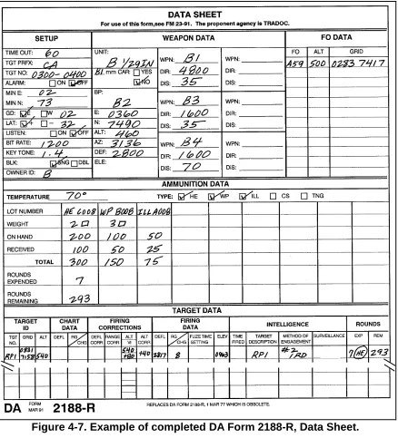
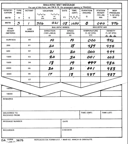
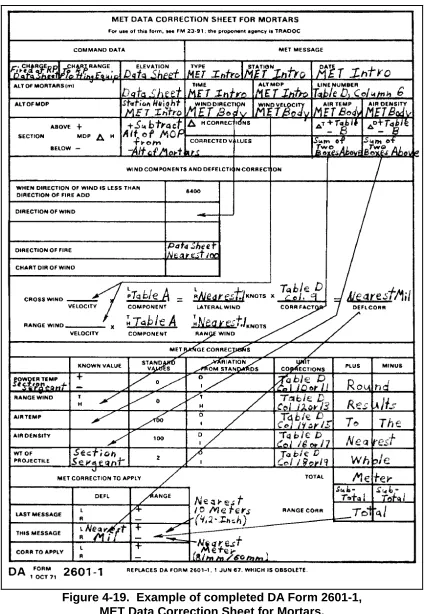
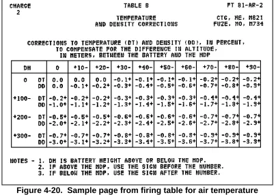
4-1. Types of Sheaves... 4-1 4-2. Computer's Record ... 4-2 4-3. Data Sheet ... 4-7 4-4. Angle T... 4-10 4-5. Firing Tables ... 4-12 4-6. Ballistic Meteorological Message ...4-17 4-6.1 Computer MET Message ... 4-31.1 4-7. The 6400-Mil MET Message ... 4-32 4-8. Computation of MET Corrections for Large Sector
Capability ... 4-32 4-9. Meteorological (MET) Corrections... 4-35
CHAPTER 5. CALL FOR FIRE
Page
5-7. Message to Observer ... 5-5 5-8. Call-For-Fire Format ... 5-5 5-9. Authentication ... 5-6
Part Three
MORTAR BALLISTIC COMPUTER
CHAPTER 6. INTRODUCTION
6-1. Description ... 6-1 6-2. Audio Alarm... 6-7 6-3. Capabilities... 6-8 6-4. Memory Storage ... 6-9 6-5. Error Messages ...6-9
CHAPTER 7. PREPARATION OF FIRE CONTROL EQUIPMENT
7-1. Types of Data Entry... 7-1 7-2. Initialization ... 7-5
CHAPTER 8. TYPES OF MISSIONS
8-1. Grid Mission... 8-1 8-2. Shift Mission ... 8-5 8-3. Polar Mission ... 8-7 8-4. Technical Fire Control ... 8-9 8-5. Sheaves... 8-10 8-6. Traversing Fire ... 8-11 8-7. Searching or Zone Fire ... 8-19 8-8. Illumination ... 8-22 8-9. Coordinated Illumination ... 8-25
CHAPTER 9. SPECIAL PROCEDURES
9-1. Registration and Sheaf Adjustment... 9-1 9-2. Mean Point of Impact Registration ... 9-3 9-3. Radar Registration... 9-5 9-4. Final Protective Fires ... 9-8 9-5. Immediate Smoke or Immediate Suppression... 9-11 9-6. Quick Smoke ...9-12 9-7. Special Keys and Functions ... 9-16
CHAPTER 10. DIGITAL MESSAGE DEVICE SUPPORTED
Page
Part Four
M16 AND M19 PLOTTING BOARDS
CHAPTER 11. INTRODUCTION
11-1. M16 Plotting Board ... 11-1 11-2. M19 Plotting Board ... 11-3 11-3. Capabilities... 11-4
CHAPTER 12. PREPARATION OF FIRE CONTROL EQUIPMENT
12-1. Observed Firing Charts ... 12-1 12-2. Modified-Observed Firing Chart... 12-14 12-3. Transfer of Targets ... 12-19 12-4. Deflection Conversion Table ...12-22 12-5. Grid Mission... 12-24 12-6. Shift Mission ... 12-24 12-7. Polar Mission ...12-25
CHAPTER 13. TYPES OF MISSIONS
13-1. Traversing Fire ... 13-1 13-2. Searching and Zone Fire... 13-8 13-3. Illumination ... 13-13
CHAPTER 14. SPECIAL CONSIDERATIONS
14-1. Registration and Sheaf Adjustment... 14-1 14-2. Mean Point of Impact Registration ...14-12 14-3. Vertical Interval Correction Factors ...14-16 14-4. Radar Registration... 14-18 14-5. Final Protective Fires ... 14-20
By Order of the Secretary of the Army:
ERIC K. SHINSEKI
General, United States Army Chief Of Staff
Official:
JOEL B. HUDSON
Administrative Assistant to the Secretary of the Army
0000506
DISTRIBUTION:
PART ONE
INTRODUCTION AND FUNDAMENTALS OF MORTAR GUNNERY
CHAPTER 1
INTRODUCTION
The mission of the mortar platoon is to provide close and immediate indirect fire support for the maneuver battalion and companies.
1-1. ORGANIZATION
Mortars are organized as part of a company and battalion. They are either sections or platoons in airborne, ranger, air assault, light infantry companies, and cavalry troops. They are organized as platoons in all tank and infantry mechanized battalions. Regardless of the organization to which they belong, mortars have the battlefield role of providing the maneuver commander with immediate indirect fires. They can fulfill that mission when all of the elements responsible for placing effective mortar fire on the enemy are properly trained.
1-2. GENERAL DOCTRINE
Doctrine demands the timely and accurate delivery of indirect fire to meet the needs of supported units. All members of the indirect fire team must be thoroughly indoctrinated with a sense of urgency. They must strive to reduce, by all possible measures, the time required to execute an effective fire mission.
a. For mortar fire to be effective, it must be dense enough and must hit the target at the right time with the right projectile and fuze. Good observation is required for effective mortar fire. Limited observation results in a greater expenditure of ammunition and less effective fire. Some type of observation is desirable for every target to ensure that fire is placed on the target. Observation of close battle areas is usually visual. When targets are hidden by terrain features or when great distance or limited visibility is involved, observation may be radar or by sound. When observation is possible, corrections can be made to place mortar fire on the target by adjustment procedures; however, lack of observation must not preclude firing on targets that can be located by other means.
b. Mortar fire must be delivered by the most accurate means that time and the tactical situation permit. When possible, survey data will be used to accurately locate the mortar position and target. Under some conditions, only a rapid estimate of the relative location of weapons and targets may be possible.
massed fires cannot be achieved, the time required to bring effective fires on the target should be kept to a minimum.
d. The greatest demoralizing effect on the enemy can be achieved by the delivery of a maximum number of rounds from all the mortars in a mortar section or platoon in the shortest possible time.
e. Mortar units must be prepared to handle multiple fire missions. They can provide an immediate, heavy volume of accurate fire for sustained periods. Mortars are area fire weapons; however, units can employ them to neutralize or destroy area or point targets, to screen large areas with smoke for sustained periods, or to provide illumination.
f. In the armor and mechanized infantry battalions, units can normally fire mortars from mortar carriers. However, mortars maintain their ground-mounted capability. Firing from a carrier permits rapid displacement and quick reaction to the tactical situation.
1-3. INDIRECT FIRE TEAM
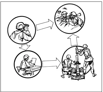
Indirect fire procedures are a team effort (Figure 1-1). They include locating the target, determining firing data, applying data to the mortar, and preparing the ammunition. Since the mortar is normally fired from the defilade (where the crew cannot see the target), the indirect fire team gathers and applies the required data. The team consists of a forward observer (FO), a fire direction center (FDC), and a mortar squad.
a. The team mission is to provide accurate, timely response to the unit it supports. Effective communication is vital to the successful coordination of the efforts of the indirect fire team.
b. The forward observer (FO), as part of the fire support team (FIST), is normally provided by a direct support (DS) artillery battalion. One 4-man FO team supports each mechanized infantry company. The light infantry company is supported by a 10-man company-level FO team. The team is composed of a lieutenant, a staff sergeant, a radio-telephone operator, a driver with a HMMWV at company headquarters, and six FOs (one 2-man team for each infantry platoon in the company). The FO’s job is to find and report the location of targets, and to request and adjust fire.
c. The FDC has two computer personnel in each section (except the 60-mm squad, which does not have assigned FDC personnel) who control the mortar firing. They convert the data from the FO in a call for fire into firing data that can be applied to the mortar and ammunition.
Figure 1-1. The indirect fire team.
1-4. MORTAR POSITIONS
Units should employ mortars in defilade positions when possible to protect mortars from the enemy direct fire and observation. These positions can also take the greatest advantage of the indirect fire role of mortars.
a. The use of defilade precludes sighting the weapons directly at the target (direct lay). This is necessary for survivability.
b. Mortars are indirect fire weapons. Therefore, special procedures ensure that the weapon and ammunition settings used will cause the projectile to burst on or at the proper height above the target. A coordinated effort by the indirect fire team also ensures timely and accurate engagement of targets.
c. The steps used in applying the essential information and engagement of a target from a defilade position are as follows:
(1) Locate targets and mortar positions.
(2) Determine chart data (direction, range, and VI from mortars to targets). (3) Convert chart data to firing data.
(4) Apply firing data to the mortar and to the ammunition.
CHAPTER 2
FUNDAMENTALS OF MORTAR GUNNERY
This chapter discusses the elements of firing data, ballistics, firing tables, fire planning, target analysis, and methods of attack. This information enables the FDC to engage the enemy even during adverse conditions.
Section I. ELEMENTS OF FIRING DATA AND BALLISTICS
Firing data are applied to the ammunition and the mortar so that the fired projectile bursts at the desired location. Those data are based on the direction, horizontal range, and vertical interval from the mortar to the target, the pattern of bursts desired at the target, and MET conditions.
2-1. DIRECTION
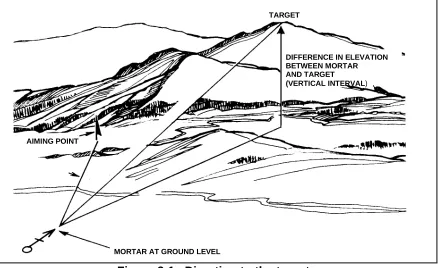
In mortar gunnery, direction is a horizontal angle measured from a fixed reference. The indirect fire team normally measures direction in mils clockwise from grid north, which is the direction of the north-south grid lines on a tactical map. The team emplaces its mortars on a mounting azimuth, then uses the direction to make angular shifts onto the target. Direction to the target may be computed, determined graphically, or estimated (Figure 2-1, page 2-2).
NOTE: The unit of angular measurement in mortar gunnery is the mil. A mil equals about 0.056 of a degree. There are 17.8 mils in a degree and 6400 mils in a 360-degree circle.
2-2. RANGE
Range is the horizontal distance, expressed in meters, from the mortars to the target. It is computed, measured graphically, or estimated. The range of a projectile depends on its muzzle velocity (which depends on charge and other factors) and the elevation of the mortar.
2-3. VERTICAL INTERVAL
Vertical interval is the difference in altitude between the mortar section and the target or point of burst. It is determined from maps, by survey, or by a shift from a known point.
2-4. DISTRIBUTION OF BURSTS
TARGET
AIMING POINT
MORTAR AT GROUND LEVEL
[image:12.612.73.511.73.341.2]DIFFERENCE IN ELEVATION BETWEEN MORTAR AND TARGET (VERTICAL INTERVAL)
Figure 2-1. Direction to the target.
2-5. INTERIOR BALLISTICS
Interior ballistics deals with the factors affecting the motion of a mortar round before it leaves the muzzle of the barrel. The total effect of all interior ballistic factors determines the velocity with which the projectile leaves the muzzle. That velocity is called muzzle velocity and is expressed in meters per second (MPS).
2-6. NATURE OF PROPELLENTS AND PROJECTILE MOVEMENTS
Propellent is a low-order explosive that burns rather than detonates. The mortar fires semifixed ammunition. When the gases from the burning propellent develop enough pressure to overcome projectile weight and initial bore resistance, the projectile begins to move.
a. Gas pressure peaks quickly and subsides gradually after the projectile begins to move. The peak pressure, together with the travel of the projectile in the bore, determines the speed at which the projectile leaves the barrel.
b. Factors that affect the velocity of a mortar-ammunition combination are as follows:
(1) An increase or decrease in the rate of burning of the propellent increases or decreases gas pressure.
(2) An increase in the size of the chamber of the weapon, without a corresponding increase in the amount of propellent, decreases the gas pressure.
(3) Gas escaping around the projectile in the barrel decreases the pressure.
(5) An increase in bore resistance at any time has a dragging effect on the projectile and decreases velocity. Temporary variations in bore resistance are caused by carbon buildup in the barrel.
2-7. STANDARD MUZZLE VELOCITY
Firing tables give the standard muzzle velocity for each charge. Values are based on a standard barrel and are guides, since they cannot be reproduced in a given instance. A specific mortar-ammunition combination cannot be selected with the assurance that it will result in a standard muzzle velocity when fired. Charge velocities are established indirectly by the military characteristics of a weapon. Since mortars are high-angle of fire weapons, they require greater variation in charges than do howitzers, which are capable of low-angle of fire. This variation helps achieve a range overlap between charge zones and desired range-trajectory. Other factors considered in establishing charge velocities are the maximum range specified for the weapon, and the maximum elevation and charge (with resulting maximum pressure) that the weapon can accommodate.
2-8. NONSTANDARD MUZZLE VELOCITY
In mortar gunnery techniques, nonstandard velocity is expressed as a variation (plus or minus MPS) from an accepted standard. Round-to-round corrections for dispersion cannot be made. Each factor causing nonstandard muzzle velocity is treated as independent of related factors.
a. Velocity Trends. Not all rounds of a series fired from the same weapon using the same ammunition lot will develop the same muzzle velocity. Some muzzle velocities are higher than average, and some are lower. This is called velocity dispersion. Under most conditions, the first few rounds follow a somewhat regular pattern rather than the random pattern associated with normal dispersion. This is called velocity trend. The magnitude and extent (number of rounds) of velocity trends vary with the mortar, charge, barrel condition, and firings that precede the series. Velocity trends cannot be predicted, so computer personnel should not attempt to correct for their effects.
b. Ammunition Lots. Each lot of ammunition has its own performance level when related to the same mortar barrel. Although the round-to-round probable error (PE) within each lot is about the same, the mean velocity developed by one lot may be higher or lower than that of another lot. Variations in the projectile, such as, the diameter and hardness of the rotating disk, affect muzzle velocity. Projectile variations have a much more apparent effect on exterior ballistics than on interior ballistics.
c. Tolerances in New Weapons. All new mortars of a given size and model do not always develop the same muzzle velocity. In a new barrel, the main factors are variations in the powder chamber and in the interior dimensions of the bore. If a battalion armed with new mortars fired with a common lot of ammunition, a velocity difference of 3 or 4 MPS between the mortars with the highest and lowest muzzle velocity would be normal.
to initial projectile movement and lessening pressure buildup. Wear can be reduced by careful selection of the charge and by proper cleaning of the weapon and ammunition.
e. Rotating Disks. Rotating disks allow proper seating, keep gases from escaping between the bore and the projectile, and create proper resistance to the projectile's initial movement. Also, disks allow uniform pressure buildup but minimum drag on the moving projectile, and they help give it a proper spin. Dirt or burrs on the rotating disk cause improper seating, which increases barrel wear and reduces muzzle velocity. If the bore is excessively worn, the rotating disk may not properly engage the lands and grooves to impart proper spin to the 4.2-inch mortar projectile. Not enough spin reduces projectile stability in flight, which can result in dangerously short, erratic rounds.
f. Temperature of the Propellent. Any combustible material burns rapidly when it is heated before ignition. When a propellent burns more rapidly, the resultant pressure on the projectile is greater, increasing muzzle velocity. Firing tables show the magnitude of that change. Appropriate corrections to firing data can be computed, but such corrections are valid only if they reflect the true propellent temperature. The temperature of propellents in sealed packing cases remains fairly uniform, though not always standard (70 degrees F).
(1) Once the propellent is unpacked, its temperature tends to approach the prevailing air temperature. The time and type of exposure to weather result in propellent temperature variations between mortars. It is not practical to measure propellent temperature and to apply corrections for each round fired by each mortar. Propellent temperatures must be kept uniform; if they are not, firing is erratic. A sudden change in propellent temperature can invalidate even the most recent corrections.
(2) To let propellents reach air temperature uniformly, ready ammunition should be kept off the ground. Ammunition should be protected from dirt, moisture, and direct sunrays. An airspace should be between the ammunition and protective covering.
(3) Enough rounds should be unpacked so that they are not mixed with newly unpacked ammunition. They should be fired in the order in which they are unpacked; hence, opened rounds are fired first.
g. Moisture Content of Propellent. Handling and storage can cause changes in the moisture content of the propellent, which affects the velocity. This moisture content cannot be measured or corrected; also, ammunition must be protected from moisture.
h. Weights of Projectile. The weight of like projectiles varies within certain weight zones. For the lighter 60-mm and 81-mm projectiles, the difference is minimal and has little affect on muzzle velocity. For the 4.2-inch mortar projectile, however, the difference must be considered. The appropriate weight zone is stenciled on the projectile as squares ([]) of weight. A heavier-than-standard projectile is harder to push through the barrel and has less muzzle velocity. A lighter projectile is easier to push through the barrel and has a higher muzzle velocity. The weight of the projectile is also a factor in exterior ballistics.
i. Barrel Temperature. The temperature of the barrel affects the muzzle velocity. A cold barrel offers more resistance to projectile movement than a warm barrel.
to coppering. Unless the barrel is properly cleaned and cared for, such residues increase subsequent barrel wear by pitting, thus increasing abrasion by the projectiles.
k. Oil or Moisture. Oil or moisture in the barrel or on the rotating disk tends to increase the velocity of a round by causing a better initial gas seal and reducing projectile friction on the bore surface. Conversely, too much oil or moisture in the barrel decreases velocity, causing a short round.
2-9. EXTERIOR BALLISTICS
Exterior ballistics—mainly gravity and air—affect the motion of a projectile after it leaves the muzzle of the barrel. Gravity causes the projectile to fall; air resistance impedes it. When projectiles are fired in the air, their paths differ since projectiles of different sizes or weights respond differently to the same atmospheric conditions. Also, a given elevation and muzzle velocity can result in a wide variety of trajectories, depending on the combined properties of the projectile and the atmosphere.
2-10. TRAJECTORY
Trajectory (Figure 2-2) is the flight path followed by a projectile from the muzzle of the mortar to its point of impact. The ascending branch is the portion of the trajectory traced while the projectile is rising from its origin. The descending branch is that portion of the trajectory traced while the projectile is falling. The summit is the highest point of the trajectory. It is the end of the ascending branch and the beginning of the descending branch. The maximum ordinate is the altitude (in meters) at the summit above the point of origin.
ORIGIN GROUND LEVEL POINT OF IMPACT
MAXIMUM ORDINATE
SUMMIT
ASCENDING BRANCH
DESCENDING BRANCH
Figure 2-2. Elements of the trajectory.
a. Trajectory in Atmosphere. The resistance of the air to a projectile depends on the air movement, density, and temperature. An assumed air density and temperature, and a condition of no wind, are used as a point of departure for computing firing tables. The air structure so derived is called the standard atmosphere.
Its descending branch is shorter than its ascending branch, and its angle of fall is greater than its angle of elevation.
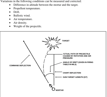
[image:16.612.70.514.232.635.2](1) The spin initially imparted to the 4.2-inch mortar projectile causes drift (Figure 2-3). This characteristic has an effect on trajectory that must be considered when aiming.
(2) A trajectory in standard atmosphere is effected by the following factors:
• Horizontal velocity decreases with continued time of flight.
• Vertical velocity is affected not only by gravity but also by air resistance. c. Standard Conditions and Corrections. Certain atmospheric and material conditions are accepted as standard. Those conditions are outlined in the introduction to the firing tables given below. When conditions vary from standard, the trajectory varies. Variations in the following conditions can be measured and corrected:
• Difference in altitude between the mortar and the target.
• Propellent temperature.
• Drift.
• Ballistic wind.
• Air temperature.
• Air density.
• Weight of the projectile.
COMMAND DEFLECTION
MORTAR
ACTUAL PATH OF PROJECTILE CAUSED BY ROTATION AND AIR PRESSURE
ANGLE OF DRIFT (GIVEN IN FIRING TABLE IN MILS)
CHART DEFLECTION
GUN-TARGET AZIMUTH (GT) TARGET
Figure 2-3. Drift.
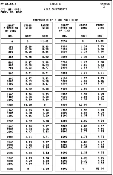
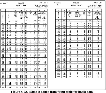
Section II. FIRING TABLES
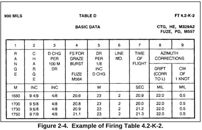
variations in the weapon, weather, and ammunition at a given time and place. The atmospheric standards in United States firing tables reflect the mean annual conditions in the north temperate zone. The main elements measured in experimental firing are angle of elevation, angle of departure, muzzle velocity, attained range, drift, and concurrent atmospheric conditions.
Figure 2-4. Example of Firing Table 4.2-K-2.
2-11. PURPOSE
The main purpose of a firing table is to provide the data required to bring effective fire on a target under any condition. Data for firing tables are obtained by firing the weapon at various elevations and charges.
2-12. UNIT CORRECTIONS
Firing tables describe unit corrections as range corrections for an increase or decrease in range, wind, air temperature, density, and projectile weight, followed by the unit value in meters.
a. Each correction is computed on the assumption that all other conditions are standard. However, any correction will differ slightly from that computed if one or more of the other conditions are nonstandard. The amount of difference depends on the effect of the other nonstandard conditions. The effect of one nonstandard condition on the effect of another nonstandard condition is known as an interaction effect. The effect of a nonstandard condition depends on how long the projectile is exposed to that condition.
2-13. STANDARD RANGE
The standard range is the range opposite the charge in the firing table, which is the horizontal distance from origin to level point. The attained range is that reached by firing with a given elevation and charge. If actual firing conditions duplicate the ballistic properties and MET conditions upon which the firing table is based, the attained range and the standard range will be equal. The command range corresponds to the given elevation and charge that must be fired to reach the target.
a. Effect of Nonstandard Conditions. Deviations from standard conditions, if not corrected in computing firing data, cause the projectile to impact or burst at other than the desired point. Nonstandard conditions that affect range also affect time of flight (TOF). Corrections are made for nonstandard conditions to improve accuracy. The accuracy of mortar fires depends on the accuracy and completeness of data available, computation procedures used, and care in laying the weapons. Accuracy should not be confused with precision. Precision is related to tightness of the dispersion pattern without regard to its nearness to a desired point. Accuracy is related to the location of the MPI with respect to a desired point.
b. Range Effects. Vertical jump is a small change in barrel elevation caused by the shock of firing. It causes minor range dispersion. In modern weapons, vertical jump cannot be predicted and is usually small, so it is not considered separately in gunnery.
(1) The weight of the projectile affects the muzzle velocity. Two opposing factors affect the flight of a projectile of nonstandard weight. A heavier projectile is more efficient in overcoming air resistance; however, its muzzle velocity is normally lower because it is more difficult to push through the barrel. An increase in projectile efficiency increases range, but a decrease in muzzle velocity decreases range. In firing tables, corrections for those two opposing factors are combined into a single correction. The change in muzzle velocity predominates at shorter times of flight; the change in projectile efficiency predominates at longer times of flight. Hence, for a heavier-than-standard projectile, the correction is plus at shorter times of flight and minus at longer times of flight. The reverse is true for a lighter-than-standard projectile.
(2) Air resistance affects the flight of the projectile in both range and deflection. The component of air resistance that is opposite to the direction of flight is called drag. Because of drag, both the horizontal and vertical components of velocity are less at any given time of flight than they would be if drag were zero, as in a vacuum. The greater the drag, the shorter the range; and the heavier the projectile, the longer the range, all other factors being equal. Some factors considered in the computation of drag are air density, air temperature, velocity, and diameter.
(a) The drag of a given projectile is proportional to the density of the air through which it passes. For example, an increase in air density by a given percentage increases the drag by the same percentage. Since the air density at a particular place, time, and altitude varies widely, the standard trajectories reflected in the firing tables are computed with a fixed relation between density and altitude. As the air temperature increases, the drag decreases, thereby increasing range.
percent of air density (1 percent of drag) increases with an increase of charge (muzzle velocity).
(c) Two projectiles of identical shape but different size do not experience the same drag. For example, a larger projectile offers a larger area for the air to act upon; hence, its drag will be increased.
(3) The finish of the shell surface affects the muzzle velocity. A rough surface on the projectile or fuze increases air resistance, thereby decreasing range.
(4) The ballistic coefficient of a projectile is its efficiency in overcoming air resistance compared to an assumed standard projectile. Each projectile and projectile lot, however, has its own efficiency level. Therefore, to establish firing tables, one specific projectile lot must be selected and fired. Based on the performance of that lot, standard ranges are determined. The ballistic coefficient of that lot becomes the firing table standard. However, other projectile lots of the same type may not have the same ballistic coefficient as the one reflected in the firing tables. If one of the other lots is more efficient—that is, has a higher ballistic coefficient than the firing table standard—it will achieve a greater range when fired. The reverse is true for a less efficient projectile lot.
NOTE: For ease in computations, all projectile types are classified into certain standard groups.
(5) Range wind is that component of the wind blowing parallel to the direction of fire and in the plane of fire. Range wind changes the relationship between the velocity of the projectile and the velocity of the air near the projectile. If the air is moving with the projectile (tail wind), it offers less resistance to the projectile and a longer range results; a head wind has the opposite effect.
Section III. FIRE PLANNING
The ability of mortar platoons to engage targets with accurate and sustained fires depends on the precision and detail of fire planning. Fire planning is concurrent and continuous at all levels of command. The principles of fire planning used by field artillery also apply to mortars. These principles are close and continuous support of the battalion, coordination with adjacent and higher units, and continuous planning.
2-14. TERMINOLOGY
Some of the common terms used in fire planning are defined as follows:
a. A target may be troops, weapons, equipment, vehicles, buildings, or terrain that warrant engagement by fire and that may be numbered for future reference. A solid cross designates a target on overlays, with the center of the cross representing the center of the target. The target number consists of two letters and four numbers allocated by higher headquarters. That numbering system identifies the headquarters that planned the target, distinguishes one target from another, and prevents duplication.
b. Targets of opportunity are targets for which fires have not been planned. Planned targets are scheduled or on call.
(2) On-call targets are fired only upon request. They include targets for which firing data are kept current, and targets for which firing data are not prepared in advance—for example, a prominent terrain feature, such as a road junction, that the FO may use as a reference point.
c. A group of targets consists of two or more targets to be fired at the same time. Targets are graphically portrayed by circling and identifying them with a group designation (Figure 2-5). Mortars are normally assigned groups of targets. The group designation consists of the letters assigned to the maneuver brigade by the division TOC with a number inserted between them. For example, if the brigade is assigned the letters A and B, the first group of targets planned by the DS battalion FDC is designated A1B, the second group A2B, and so on. Similarly, if the division TOC has designated the letters A and Y, the first group is A1Y and the second is A2Y. The designation of a group of targets does not preclude firing at any individual target within the group.
Figure 2-5. Group of targets.
d. A series of targets (Figure 2-6) is a number of targets or groups of targets planned to support the operation. For example, a series of targets may be planned on a large objective so that fires are lifted or shifted as the support unit advances. Graphically, a series is shown as individual targets or groups of targets within a prescribed area. The series is given a code name. The fact that a series of targets has been formed does not preclude the attack of individual targets or groups of targets within a series.
A1B
AB0062
AB0062
Figure 2-6. Series of targets.
e. The final protective fire (Figure 2-7) is an immediately available prearranged barrier of fire designed to impede enemy movement across defensive lines or areas. It is integrated with the maneuver commander's defensive plans. The shape and pattern of FPF may be varied to suit the tactical situation. The maneuver commander is responsible for the precise location of FPF. The FIST chief is responsible for reporting the desired location of the FPF to the supporting FDC. Authority to call for the FPF is vested in the maneuver commander (normally, the company commander or platoon leader) in whose area the FPF is located. The FPF is represented on a map or firing chart by a linear plot. The length of the plot depends on the type of unit assigned to fire the FPF. The designation of the unit that will fire the FPF is placed above the plot representing the FPF.
Figure 2-7. Final protective fires symbol.
f. A preparation is the intense delivery of fires according to a time schedule to support an attack. The commander decides to fire a preparation and orders the attack.
g. A counterpreparation is the delivery of intense planned fires when the imminence of an enemy attack is discovered. It is designed to break up enemy
DOG
AB1
AB0048 AB0052 AB0051
AB0050
AB0049
formations, to disorganize command and communications systems, to reduce the effectiveness of enemy preparations, and to impair the enemy's offensive spirit. The counterpreparation is fired on the order of the force commander. The fires are planned and assigned to firing units, and firing data are kept current.
h. A program of targets is a number of targets planned on similar areas such as a countermortar program. Although the artillery battalion in DS of the brigade normally plans counterpreparation, and programs and designates groups and series of targets, the battalion mortar platoon and company mortar section are considered in the planning since they are subsequently assigned the targets.
i. Harassing fires are planned on known enemy positions to inflict losses, to curtail movement, and to disrupt the enemy to keep him off balance. Interdiction fires are planned on critical areas (bridges, possible observation posts, road junctions) to deny the enemy the use of those areas. Harassing and interdiction fires should include the number of rounds to be fired and the times of firing. Varying the number of rounds and firing at irregular intervals greatly increase the effectiveness of those fires.
2-15. TARGET CONSIDERATIONS
Planned targets include areas of known, suspected, and likely enemy locations, and prominent terrain features. Those areas are determined through intelligence sources, knowledge of the situation, and map and terrain study. They are planned without regard to boundaries or weapon abilities. Duplication of effort will be resolved by the next higher headquarters.
a. Known Enemy Locations. Fires are planned on all known enemy locations that could hinder the support unit's mission.
b. Suspected Enemy Locations. These include areas such as probable OPs, troop positions, assembly areas, avenues of approach, and routes of withdrawal. Fires are planned on suspected locations so that fires are available if the target is confirmed.
c. Likely Enemy Locations. Targets in this category are determined from a careful study of the terrain and maps, and from a knowledge of the enemy's methods of placing troops and weapons.
d. Prominent Terrain Features. Hilltops, road junctions, manufactured objects, and other easily identifiable locations on a map and on the ground are planned as targets to provide reference points from which to shift to targets of opportunity.
2-16. SUPPORT OF OFFENSIVE OPERATIONS
Fires planned to support an attack consist of a preparation, if ordered, and subsequent fires. The preparation may be delivered before the advance of the assault elements from their LD and may continue for a short time thereafter. Fires planned for the preparation are normally limited to known targets and suspected areas. The delivery of fires on scheduled targets should be consistent with the threat imposed, time available for coordination, and availability of ammunition.
and control installations, and later the attack of enemy forward elements. The detail and extent of preparation plans depend on the availability of intelligence.
b. Battalion Mortar Platoon. The battalion fire plan table for a preparation may include fires by the battalion mortar platoon. Once the preparation is fired, the mortar platoon is available for fire support of the battalion maneuver elements. In some situations, the battalion commander may exclude the mortars from the preparation and retain them for targets of opportunity throughout the attack.
c. Company Mortar Section. The company mortar section may be required to fire preparation fires. Those fires are limited to the engagement of enemy forward elements. Before committing the mortars to preparation fires, the commander should consider ammunition resupply and availability of mortars to quickly attack targets of opportunity.
d. Fires Supporting the Attack. Fires planned in support of the attack are shifted to conform to the movements of the supported unit. They are planned in the form of targets, groups of targets, and series of targets. They may be fired on a time schedule or on-call and may include targets from the LD to the objective, on the objective, and beyond the objective.
e. Objectives. Supporting fires have several specific objectives. They assist the advance of the supported unit by neutralizing enemy forces, weapons, and observation short of the objective. They assist the supported unit in gaining fire superiority on the objective so that the assaulting force can close to assault distance, and they protect the supported unit during reorganization. (On-call targets are planned on likely assembly areas and routes for enemy counterattacks.) Supporting fires prevent the enemy from reinforcing, supplying, or disengaging his forces. Also, they quickly provide mutual fire support to lower, adjacent, and higher headquarters.
2-17. SUPPORT OF DEFENSIVE OPERATIONS
Fires in support of defensive operations include long-range fires, close defensive fires, final protective fires, and fires within the battle area.
a. Long-Range Fires. Long-range fires are designed to engage the enemy as early as possible to inflict casualties, to delay his advance, to harass him, to interdict him, and to disrupt his organization. They consist of the fires of the supporting weapons within the battle area capable of long-range fires. The enemy is engaged by long-range weapons as soon as he comes within range. As a result, the volume of fire increases as the enemy continues to advance and comes within range of additional weapons. A counterpreparation designed to disrupt the enemy's attack preparations before the attack can be fired as part of long-range fires.
b. Close Defensive Fires. Close defensive fires are supporting fires employed to destroy the enemy attack formations before the assault.
(1) The artillery and mortar FPF are integrated with the FPL of machine guns. Each artillery battery normally fires one FPF. The mortar platoon of the battalion may fire one or two FPF; however, the platoon's fires are more effective in one FPF than in two.
(2) The FPF of the DS artillery are available to the supported brigade and its battalions. The FPF of any artillery reinforcing DS battalion is normally available. The brigade commander designates the general areas for available FPF or allocates them to the maneuver battalions. The maneuver battalion commander, in turn, designates general locations or allocates them to maneuver companies.
d. Fires Within the Battle Area. The precise location of an FPF is the responsibility of the company commander in whose sector it falls. The exact locations of FPF within each forward company are included in the fire plan and reported to battalion. Fires within the battle area are planned to limit penetrations and to support counterattacks.
2-18. FIRE SUPPORT COORDINATION MEASURES
The FIST and fire support planners use fire support coordination measures to ensure that fires impacting in their zone will not jeopardize troop safety, interfere with other fire support means, or disrupt adjacent unit operations.
a. Boundaries. Boundaries determined by maneuver commanders establish the operational zone for a maneuver unit and the area in which the commander fires and maneuvers freely. A unit may fire and maneuver against clearly identified enemy targets near or over its boundary, as along as such action does not interfere with adjacent units.
b. Coordination Measures. Coordination measures designate portions of the battlefield where actions may or may not be taken. The fire FSCOORD/FIST chief recommends coordination measures; the commander establishes them. They facilitate operations by establishing rules and guidelines for selected areas for a given time. There are two categories: permissive and restrictive.
(1) Permissive measures. Permissive measures are drawn in black on overlays and maps. They are titled and indicate the establishing headquarters and the effective date-time group. Permissive measures allow fires into an area such as a free-fire area or across a line—for example, a coordinated fire line or FSCL—that need not be further coordinated as long as they remain within the zone of the established headquarters.
(a) A coordinated fire line is a line beyond which conventional surface fire support means (mortars, FA, NGF) may fire any time within the zone of the establishing headquarters without further coordination.
(b) A fire support coordination line is a line beyond which all targets may be attacked by any weapon system without endangering troops or requiring further coordination with the establishing headquarters. The effects of any weapon system may not fall short of this line.
(c) A free-fire area is a designated area into which any weapon system may fire without further coordination with the establishing headquarters.
establishing headquarters on a case-by-case basis. Examples of restrictive measures include a restrictive fire area, a no-fire area, a restrictive fire line, and an airspace coordination area.
(a) A restrictive fire area is an area in which specific restrictions are imposed and into which fires that exceed those restrictions will not be delivered without coordination with the establishing headquarters.
(b) A no-fire area is an area in which no fires or effects of fires are allowed. There are two exceptions: when establishing headquarters approves fires temporarily within a no-fire area on a mission basis; and when an enemy force within the no-fire area engages a friendly force, and the commander engages the enemy to defend his force.
(c) A restrictive fire line is a line established between converging friendly forces (one or both may be moving) that prohibits fires or effects from fires across the line without coordination with the affected force.
(d) An airspace coordination area is a block of airspace in the target area in which friendly aircraft are reasonably safe from friendly surface fires. It may be a formal measure but is usually informal.
2-19. COMPANY FIRE SUPPORT PLAN
The company commander's fire planning begins with receipt or assumption of a mission and continues throughout the execution of the mission. The company fire planning team consists of the company commander, FIST chief, mortar section/platoon leader, and platoon's FIST FOs. During the process of evaluating, refining, revising, and deciding how to accomplish the mission, the commander constantly seeks the most efficient and effective application of all resources to produce maximum combat power.
a. The FIST chief, as the commander's special staff officer for fire support, performs a critical role in this planning process. He ensures that the commander has all required information on available fire support and recommends how best to apply it in concert with other resources. For best results, the commander should include the team in every step of his decision-making process.
b. The company commander gives guidance to the fire planning team in the form of a concept. This concept outlines the scheme of maneuver and the desire for fire support. Later, when the FIST chief submits the proposed consolidated target list and company fire plan, the company commander approves or changes it.
c. The company commander supervises the preparation of the company fire plan and coordinates the fire planning activities. The FIST chief develops the company fire plan and consolidates it with copies of the target lists prepared by the platoon FOs. This consolidated list is then submitted to the company commander for approval.
d. The company fire planners inform the company commander of the fire support available. They also obtain the following information for or from the company commander:
• Location of forward elements.
• Scheme of maneuver.
• Known enemy locations, avenues of approach, and assembly areas.
• Fires desired.
• Location of the command post.
e. Upon receipt of this information, the fire planners start planning fires to support the company. Through map inspection and terrain analysis, the target lists are prepared (Table 2-1). If time and facilities permit, an overlay, giving a graphic representation, may also be prepared. The target list includes for each target the target number, map coordinates, description, and amplifying remarks if required. It does not include target altitudes, which are determined by the respective FDCs.
TARGET NUMBER DESCRIPTION LOCATION REMARKS
C- FPF 14898346
1-66 FPF 15508330
1-45 FPF 15908330
AA0050 DEFENSIVE TARGET 15278336 AA0051 DEFENSIVE TARGET 15368319
AA0052 HILLTOP 14848250
AA0053 HILLTOP 15038196
AA0054 CROSSROADS 15248171
AA0055 RIDGE 15118081
AA0056 MORTAR POSITION 152802 100-METER ZONE AA0150 DEFENSIVE TARGET 14948381
AA0152 DEFENSIVE TARGET 15008325 AA0153 DEFENSIVE TARGET 15528303
AA0154 OP 1428287
AA0155 OP 15108245
AA0156 HILL 15128286
AA0157 EMERGENCY
POSITION
161188288
AA0158 ROAD JUNCTION 14608190 AA0159 ROAD JUNCTION 15638160 AA0160 ROAD JUNCTION 16308183 AO7000 DEFENSIVE TARGET 15808424 AC7001 DEFENSIVE TARGET 15818353 AC7002 DEFENSIVE TARGET 15968320 AC7003 ROAD JUNCTION 15728272
AC7004 BRIDGE 152791 DESTROY ON
CALL
Table 2-1. Consolidated target list.
f. Target information can be submitted by any means available, such as telephone or radio, directly to an FDC. The FIST chief assigns numbers to targets not included in the list from the platoon FO or mortar platoon leader. Numbers from the separate target lists are transferred to the corresponding targets on the approved consolidated target list/company fire plan. The targets on the list are arranged by target number alphabetically and numerically.
g. Once the fire plan is approved, it is distributed to those who will need it to include FOs, rifle platoon leaders, FDC, company fire planners, and battalion S3. Also, the FIST chief sends a copy of the approved target list to the FSO at battalion headquarters.
Fire planning at battalion level is initiated the same as in the company. The battalion fire planning team consists of the battalion commander, S3, battalion mortar platoon leader, and FSO. The battalion mortar platoon must always be directly responsive to the desires of the battalion commander. The platoon leader takes a position that best assists the S3 in planning and obtaining fire support. The FSO is normally the battalion FSO; however, the battalion mortar platoon leader serves in the absence of the FSO.
a. The battalion commander and S3 present the commander's concept of the operation, which, as in the case of the company, includes the scheme of maneuver and the plan for fire support. After the FSO has consolidated the target lists prepared by the company fire planners, the battalion commander approves the consolidated target list as part of the battalion fire support plan. The written plan becomes an annex to the operation plan.
b. The FSO is usually the battalion FSCOORD and receives target lists from the company's FIST chief and from the battalion mortar platoon leader. Once duplications are deleted, all fire plans are updated by assigning target numbers or by consolidating targets. Then, the FSO submits all fire plans and target lists to the battalion S3 as the proposed battalion fire support plan.
c. The S3 ensures that the proposed fire support plan supports the scheme of maneuver. After the battalion commander approves the fire plan, the plan becomes an annex to the battalion operation plan. It is disseminated to all subordinate elements to include rifle companies and the battalion mortar platoon.
Section IV. TARGET ANALYSIS AND ATTACK
The FIST chief, when planning fires or when deciding to engage a target, ensures that the fire conforms to the scheme of maneuver of the support unit. He must also be informed of the present enemy situation. In target analysis and determining the method of attack, the FDC chief considers target description, registration data, size of attack area, and the maximum rate of fire.
2-21. TARGET DESCRIPTION
The method of attacking a target depends largely on its description, which includes the type, size, density, cover, mobility, and importance. Those factors are weighed against the guidelines established by the commander. The FDC then decides the type of projectile, fuze, fuze setting, and ammunition to be used.
a. Fortified targets must be destroyed by point-type fire using projectiles and fuzes appropriate for penetration. Mortar fire does not usually destroy armor, but it can harass and disrupt armor operations.
b. A target consisting of both men and materiel is normally attacked by area fire using air or impact bursts to neutralize the area. Flammable targets are engaged with HE projectiles to inflict fragmentation damage, and then with WP projectiles to ignite the material.
c. The method of attacking a target is governed by the results desired: suppression, neutralization, or destruction.
up. Smoke is used to blind or confuse, but the effect lasts only as long as fires are continued.
(2) Neutralization knocks the target out of the battle temporarily. Ten percent or more casualties usually neutralize most units. The unit becomes effective again when casualties are replaced and equipment repaired.
(3) Destructive fires put the target out of action permanently. A unit with 30 percent or more casualties is usually rendered permanently ineffective, depending on the type and discipline of the force. Direct hits are required on hard materiel targets.
2-22. REGISTRATION AND SURVEY CONTROL
Firing corrections within the transfer limits should be maintained through registration, survey data, and current MET message. When those data are unavailable or inadequate, targets should be attacked with observed fire since unobserved fires may be ineffective. Surveillance should be obtained on all missions to determine the results of the FFE. If accurate, FFE without adjustments is highly effective against troops and mobile equipment because damage is inflicted before the target can take evasive action. All destruction missions and missions fired at moving targets must be observed, and FFE should be adjusted on the target.
2-23. SIZE OF ATTACK AREA
The size of the attack area is determined by the size of the target, or by the size of the area in which the target is known or suspected to be located. That information is usually an estimate based on intelligence and experience in similar situations. The size of the attack area is limited when considering units to fire. Mortars are the best weapons for engaging targets in depth. This is due to their versatility in making range changes and maintaining high rates of fire. All mortars can fire traversing fires with only minor manipulations.
2-24. MAXIMUM RATE OF FIRE
The greatest effect is achieved when surprise fire is delivered with maximum intensity. Intensity is best attained by massing the fires of several organic battalion units using TOT procedures. The intensity of fires available is limited by each unit's maximum rate of fire (Table 2-2) and ammunition supply. Maximum rates cannot be exceeded without danger of damaging the tube. To maintain those rates (either to neutralize a target or to attack a series of targets), mortars must be rested or cooled from previous firing. If not, the heat can cause ignition of the increment or charges on a round before it reaches the bottom of the barrel. The lowest charge possible should be used during prolonged firing, since heating is more pronounced with higher charges.
CARTRIDGE MORTAR MAXIMUM SUSTAINED
60-mm MORTAR
M720 M49AA
M224 30 RPM FOR 4 MINUTES 18 RPM FOR 4 MINUTES
20 RPM 8 RPM 81-mm MORTAR M362 M362 M29 M29E1
15 RPM FOR 2 MINUTES 27 RPM FOR 1 MINUTE 25 RPM FOR 2 MINUTES 30 RPM FOR 1 MINUTE
4 RPM
CARTRIDGE MORTAR MAXIMUM SUSTAINED M374/M375 M374/M375 M374A3 M821 M29 M29E1 M252
18 RPM FOR 2 MINUTES 30 RPM FOR 1 MINUTE 25 RPM FOR 2 MINUTES 30 RPM FOR 1 MINUTE 30 RPM FOR 2 MINUTES
5 RPM
8 RPM 8 RPM 15 RPM
4.2-INCH MORTAR
ALL AMMUNITION M30 18 RPM FOR 1 MINUTE THEN
9 RPM FOR THE NEXT 5 MINUTES 3 RPM 120-mm MORTAR NDI M57 (NDI) M68 (NDI) M91 (NDI) M933 M934 M929 (WP) M930 (ILLUM) M120 M120/M121
16 RPM FOR 1 MINUTE
16 RPM FOR 1 MINUTE 16 RPM FOR 1 MINUTE 16 RPM FOR 1 MINUTE 16 RPM FOR 1 MINUTE
4 RPM
4 RPM 4 RPM 4 RPM 4 RPM
Table 2-2. Rates of fire.
2-25. AMOUNT AND TYPE OF AMMUNITION
The amount of ammunition available is an important consideration in the attack of targets. The CSR should not be exceeded except by authority of higher headquarters. When the CSR is low, missions should be limited to those that contribute the most to the mission of the supported units. When the CSR is high, missions fired may include targets that affect planning or future operations and targets that require massing of fires without adjustment.
a. The selection of a charge with which to engage a target depends on the elevation required. The range and terrain dictate the elevation to be used. Hence, targets at a great distance require the lowest elevations and greatest charge, while targets in deep defilade require the highest elevations. Targets in deep defilade and at great range are hard to engage. This is due to the low elevation required to reach those targets, which prevents the round from having the high trajectory needed. The 4.2-inch mortar uses one of three constant elevations and makes range changes by varying the charge. The 60-mm, 81-mm, and 120-mm mortars vary both the elevation and charge but attempt to stay at the lowest charge while varying the elevation.
b. The type of ammunition selected to engage a target depends on the nature of the target and characteristics of the ammunition available.
(1) High explosive (HE) is used for destruction, harassing, interdiction and neutralization fire.
(2) Chemical ammunition is used for producing casualties, incendiary effects, screening, marking, and harassing. The types of chemical projectiles include gas (CS) and white phosphorus (WP).
(3) Illumination uses a time fuze that gives an airburst depending on the time setting. The setting on the charge and elevation fired when the time fuze is used. The HOB can be adjusted to give the best illumination on the desired location.
(1) Quick and superquick fuzes. Quick and superquick fuzes are used for impact detonation. When the HE projectile with a quick or superquick fuze passes through trees, detonation may occur in the foliage. Therefore, its effectiveness may be either improved or lost, depending on the density of the foliage and the nature of the target.
(2) Proximity fuzes. Proximity fuze is used with HE ammunition to obtain airbursts. A proximity or VT fuze detonates automatically upon approach to the object. It is used to obtain airbursts without adjusting the HOB. If the proximity element fails to function, a fuze quick-action occurs upon impact. The HOB varies according to the caliber of projectile, the angle of fall, and the type of terrain in the target area. If the terrain is wet or marshy, the HOB is increased. Light foliage has little effect on a proximity fuze, but heavy foliage increases the HOB by about the height of the foliage. The greater the angle of fall, the closer the burst is to the ground.
(3) Fuze delay. Fuze delay produces a mine action caused by the round’s penetration before detonation. Fuze delay can be used to destroy earth and log emplacements. It is also effective against some masonry and concrete structures. Fuze delay is not used against armor. The depth of penetration depends on the type of soil and terminal velocity of the round.
(4) Multioption. Multioption fuze gives the user the option to select and use all types of fuzes previously mentioned. It has the setting of delay, impact, near surface burst, and proximity. This type of fuze will be replacing the other fuzes in the future.
(5) Three-fuze family. The M734 multioption fuze, the M745 point-detonating fuze, and the electronic time fuze make up the three-fuze family. The current M734 multioption fuze has received a materiel change, which is designated the M734A1 and fielded on the M929, 120-mm smoke. The M745 point-detonating fuze is fielded on the 60-mm/120-mm smoke, and the M933, 120-mm HE (training) round. These three fuzes are used on all 60-mm 81-mm, and 120-mm service and training rounds.
2-26. UNIT SELECTION
The unit selected for a mission must have weapons of the proper caliber and range to cover the target area quickly, effectively, and economically. Many targets are of such size as to allow a wide choice for selecting the units to be employed. If the unit selected to fire cannot mass its fires in an area as small as the target area, ammunition is wasted. Conversely, if a unit can cover only a small part of the target area at a time, surprise is lost during the shifting of fire. Also, the rate of fire for the area may not be adequate to get the desired effect. The decision is often critical as to whether to have many units firing a few rounds on a large target or a few units firing many rounds. Several factors affect the selection of units and the number of rounds to fire on a target. Some of those factors are discussed below.
a. Availability of Mortar Fire. When the number of available mortar units is small, more targets must be assigned to each mortar unit.
b. Size of the Area to be Covered. The size of the area to be covered must be compared to the effective depth and width of the sheaf to be used by the platoon or platoons available.
c. Increased Area Coverage. Targets greater in depth or width than the standard sizes can be covered by—
(1) Increasing the number of units firing.
(2) Dividing the target into several targets and assigning portions to different firing elements.
(3) Shifting fire laterally or using zone fire with a single unit or with a number of units controlled as a single fire unit.
(4) Traversing fire with each mortar that is covering a portion of the target.
d. Caliber and Type of Unit. The projectiles of larger calibers are more effective for destruction missions.
e. Surprise. To achieve surprise, a few rounds from many pieces are better than many rounds from a few pieces.
f. Accuracy of Target Location. Important targets that are not accurately located may justify the fire of several units to ensure coverage.
g. Dispersion. At extreme ranges for a given mortar, fire is less dense because of increasing PE. More ammunition is required to effectively cover the target. To compensate for that dispersion, the commander selects a unit, when possible, whose GT line coincides with the long axis of the target.
h. Maintenance of Neutralization and Interdiction Fires. These fires may be maintained by the use of a few small units. A unit may fire other missions during the time it also maintains neutralization or interdiction fires.
i. Vulnerability of Targets. Some targets should be attacked rapidly with massed fires while they are vulnerable. These targets could be truck parks and troops in the open.
2-27. TYPICAL TARGETS AND METHODS OF ATTACK
and compounds the problem of locating and removing the mines by hand and of moving equipment across the mined area. Mortars also require extravagant amounts of ammunition to breach barbed wire and should not be used.
TYPE OF TARGET
TYPE OF
ADJUSTMENT PROJECTILE FUZE TYPE OF FIRE
REMARKS (SEE FOOTNOTES) GROUP I VEHICLES (RENDEZVOUS) VEHICLES (MOVING) WEAPONS (FORTIFIED) WEAPONS (IN OPEN) OBSERVED, UNOBSERVED OBSERVED OBSERVED OBSERVED HE, WP HE, WP HE HE, WP SQ, VT SQ, VT SQ, DELAY VT NEUTRALIZATION, DESTRUCTION NEUTRALIZATION, DESTRUCTION NEUTRALIZATION, DESTRUCTION NEUTRALIZATION, DESTRUCTION
(1), (2), (3)
(2), (3), (5)
AIRBURSTS ARE DESIRABLE IF THE WEAPON IS FIRING. AFTER THE WEAPON IS SILENCED, IT IS ATTACKED FOR DESTRUCTION. CHOICE OF FUZE IS DETERMINED BY TYPE OF FORTIFICATION. (SEE FORTIFICA-TION.)
(1), (2), (3)
GROUP II PERSONNEL (IN OPEN) OBSERVED, UNOBSERVED OBSERVED, UNOBSERVED
VT, Q VT, Q TOT MISSIONS ARE
MOST EFFECTIVE. FUZE QUICK SHOULD BE FIRED AT LOWEST PRACTICAL CHARGE (STEEP ANGLE OF FALL GIVES BETTER FRAGMENTATION.) INTERMITTENT FIRE IS BETTER THAN CONTINUOUS FIRE. (1)
PERSONNEL (IN DUGOUTS OR CAVES)
OBSERVED HE, WP VT NEUTRALIZATION,
HARASSING, DESTRUCTION
AIRBURSTS ARE NECESSARY, BUT SURPRISE IS NOT. WP IS USEFUL IN DRIVING SOLDIERS OUT OF HOLES AND INTO THE OPEN.
TYPE OF TARGET
TYPE OF
ADJUSTMENT PROJECTILE FUZE TYPE OF FIRE
REMARKS (SEE FOOTNOTES) PERSONNEL (UNDER LIGHT COVER) ROADS AND RAILROADS SUPPLY INSTALLATIONS OBSERVED, UNOBSERVED OBSERVED, UNOBSERVED OBSERVED, UNOBSERVED HE HE HE HE, WP SQ, DELAY
SQ, VT, DELAY (RICOCHET)
DELAY, VT, Q
SQ, VT DESTRUCTION, ASSAULT, DIRECT NEUTRALIZATION DESTRUCTION, HARASSING, INTERDICTION NEUTRALIZATION, DESTRUCTION (4) (3) CRITICAL POINTS, DEFILES, FILLS, CROSSINGS, CUL-VERTS, BRIDGES, AND NARROW POR-TIONS MUST BE ATTACKED. DIREC-TION OF FIRE SHOULD COINCIDE WITH DIRECTION OF ROAD.
(1), (3)
(1) Area is neutralized with projectile HE (airbursts if practical); surprise is essential to produce casualties.
(2) Materiel remaining in the area should be attacked for destruction by using the appropriate projectile and fuze.
(3) Projectile WP should be combined with HE when the target contains flammable material and when the smoke will not obscure adjustment.
(4) Projectile HE with fuze quick is fired at intervals to clear away camouflage, earth cover, and rubble.
(5) The first objective in firing on moving vehicles is to stop the movement. For this purpose, a deep bracket is established so that the target will not move out of the initial bracket during adjustment. Speed of adjustment is essential. If possible, the column should be stopped at a point where vehicles cannot change their route and where one stalled vehicle will cause others to stop. Vehicles moving on a road can be attacked by adjusting on a point on the road and then timing the rounds fired so that they arrive at that point when a vehicle is passing it. A firing unit or several units, if available, may fire at different points on the road at the same time.
PART TWO
FIRE DIRECTION CENTER
CHAPTER 3
INTRODUCTION
This chapter contains information on the principals of fire direction procedures, organization of FDCs, and duties and responsibilities of FDC personnel.
3-1. PRINCIPLES OF FIRE DIRECTION
Fire direction is the tactical and technical employment of firepower, the exercise of tactical command of one or more units in the selection of targets, the massing or distribution of fire, and the allocation of ammunition for each mission. Fire direction also includes the methods and techniques used in FDCs to convert calls for fire into proper fire commands.
a. Tactical fire direction is the control by the FDC over the mortars in the selection of targets, the designation of the units to fire, and the allocation of ammunition for each mission.
b. The FDC is the element of the mortar platoon headquarters that controls the fire of the mortar section and relays information and intelligence from the observers to higher headquarters. Fire direction methods must ensure
(1) Close, continuous, accurate, and timely indirect fire support under all conditions of weather, visibility, and terrain.
(2) Flexibility to engage all types of targets within the company or battalion area of responsibility.
(3) The ability to engage two or more targets at the same time. (4) The ability to implement independent gun operation.
3-2. ORGANIZATION
The FDC is the element of the indirect fire team that receives the call for fire from the FO, FIST chief, or higher headquarters; determines firing data; and announces the fire command to the firing section. The FDC also determines and applies corrections to chart data and to standard firing table values to achieve accuracy in firing. Firing data normally are produced in the FDC. However, they may be produced by a squad leader when the section is firing without an FDC. Accuracy, flexibility, and speed in the execution of fire missions depend on
a. Accurate and rapid computation of firing data from the MBC and plotting board. b. Clear transmission of commands to the mortar section.
c. Accurate and rapid verification of firing data. d. Efficient division of duties.
e. Adherence to standard techniques and procedures.
f. Efficient use of FDC plotting equipment, MBC, and other data-determining devices.
g. Teamwork and operating in a specified sequence.
3-3. PERSONNEL DUTIES
The FDC of the 4.2-inch/120-mm mortar section consists of one SFC who is the section sergeant, one SSG who serves as the chief computer, one SGT who is the check computer, and one PFC who is the driver/RATELO. The FDC of the 81-mm mortar platoon consists of one SSG who serves as the section sergeant, two sergeants who are the computers, and one PFC who is the driver/RATELO.
a. Fire Direction Chief/Section Sergeant. The fire direction chief (chief computer/ section sergeant), as the senior enlisted member of the FDC, plans, coordinates, and supervises the activities of the FDC and is responsible for the training of all FDC members. The fire direction chief must operate all FDC equipment as well as supervise their operation. The fire direction chief/section sergeant also performs but is not limited to the following duties:
(1) Makes the decision to fire. When a target is reported, examines its location relative to friendly troops, boundary lines, no-fire lines, and fire coordination lines. Using that information, along with the nature of the target, the ammunition available, and the policy of the commander, decides whether to fire. If the decision is to engage the target, uses that same information in deciding how to do so.
(2) Issues the FDC order. Once the decision has been made to engage a target, issues the FAC order to inform the other members of the FDC how the mission will be conducted.
(3) Verifies corrections and commands. Verifies firing corrections obtained from a registration or a MET message before they are applied. Ensures that all firing data and fire commands sent to the mortar section are cross-checked to eliminate errors. Resolves discrepancies.
(4) Determines the altitude of a target from the map and announces it immediately after the FDC order so that the computers may compute and apply any altitude correction.
(5) Maintains records for all fire missions and all corrections to be applied.
(6) Evaluates and relays target surveillance data and intelligence reports from observers.
(7) Coordinates with the FIST chief regarding sectors of responsibility and up-to-date tactical information. If the FDC gets a call-for-fire for a target it cannot engage immediately or effectively, it must inform the FIST chief so the mission can be assigned to another firing element.
b. Section Sergeant. The section sergeant is responsible for the same duties for the 81-mm mortar FDC as the chief computer for the 4.2-inch/120-mm mortar platoon. The section sergeant also has the following duties:
(1) Supervises tactical deployment of the mortar squads. (2) Selects sites for tactical employment of mortar squads. (3) Supervises the laying of the mortar section.
(4) Supervises the section during fire missions.