GRAPHICS DISPLAY SYSTEM
REFERENCE MANUAL
GRAPHICS DISPLAY SYSTEM
REFERENCE MANUAL
January 1972
VECTOR GENERAL, INC.
8399 Topanga Canyon Blvd. Canoga Park, Calif. 91304
I 1.1 1.2 1.3 1.4 1.5 1.6 1.7 1.8 1.9 1.10 1.11 1.12 1.13 1.14 1.15 1.16, 1.17 1.18 1.19· 1.20 1.21 1.22 1.23 1.24 1.25 II 2.1 2.2 2.3 2.4 2.5 2.6 2.7 2.8 2.9 2.10 2.11 2.12 2.13 2.14 2.15 2.16 2.17 2.18 2.19 2.20 CONTENTS
GENERAL IN FORMA TION
Introduction
...
System Description' .•..•.•.•.••••....•••..•• Standard Features .•.•••.•...•..••••.•.•.••• Optional Features .••.•••••...••••.•••..•••. System Specifications .••••••••..••.••••••••• Display Principles •••.•.•••.•••••.•••••.••• Visible Space ••..•••...•••••.•••••..•.•• Picture Space •....••...••••..••.••.••• Image Sj>ace • • . • . • • . • . • • . • . . . • • • • • • •• Absolute Vectors •••••.••••••••••••••.•••• Relative Vectors...
Incremental Vectors •••••••.•••••.•••.••••.•• Autoincrementing •••••••..•••.••••••••••••• Three-[ijmensional Display •••.••••••••••••• Character Genera ti .., . • • • • . . • • • • . • • . ••• Character Formath, ... , ••••••••••••••••••••.•• Control CharactersIntensity Levels Image Transformatiol Scaling
...
Rotation Translation
Picture TransfornR tion Picture Scaling
Intensity Modulation
SYSTEM ORGANIZATION Introduction Functional Description
...
·
... .
,... .
· ... .
...
...
...
·
'... .
Vector Coordinates ••..••.• Coordinate Scale Option
1 • • • • • • • • •
...
Rotation Option ••••...•• Displacement Vector Option Picture Control Option •...••. Vector Generator •..•••••.•• , Character Generator
...
Circular Arc Generator ' ..•••.• Cathode Ray Tube • • . . . • • . . • • . • . ' . . • • ••• Optional Control Devices • • • • . • . ••••• Alphanumeric Keyboard • • • • . • • . •••.•• Lighted Function Switches with Manual !terrupt. Joystick ••••••.•••••••••••.••••••
Light Pen ...•
Data Tablet
...
Control Dial s ••..•.•....•••.••..••.••• Programmed Input/Output Channel ••••.••.••.•• Interrupt Channel • . • • • . . • . . •••••••••••••••III
301
3.2 3.3 3.4 3.5 3.6 3.7 3.8 3.9 3.10 3.11 3.12 3.13 3.14 3.15 3.16 3.17 3.18 3«>19 3.20 3.21 3.22 3.23 3.24 3.25 3.26 3.27 3.28 3.29 3.30 3.31 3«>32 3.33 3.34 3.35 3.36 3.37 3.38 3.39
CONTENTS (Cont'd.)
DISPLAY SYSTEM PROGRAMMING
Introduction •••••••••••••••••
...
Programmatic Interface Display Sy stem Registers Destination Registers Source Registers Programmed I/O Programmed Output Programmed Input Precision of ADC Values
.
.
. .
.
. . . .
.
.
·
..
·
~... .
·
.
.
. .
·
..
·
... .
·
.
.
Priority Interrupts •••••••• • • • ••
Mode Control Register (MCR) •••••• • •
Interrupt Requests •••••••••••• • • • ••
Display P-Bit Interrupt (Subroutine/Jump Facility) •••
Display Controller Status • • • • • • • •••
Display Instructions • • • • •
Data Lists •••••
Word Formats ••
Control Display Instructions ••
No Operation ••••••••••
Halt . . . .
.
.
Register Change Display Instructions Load Registers
OR to Registers AND to Registers ADD to Registers ••
Display Write Instructions ••
Vector Relative
.
.
·
.
Vector Relative Auto-X Vector Relative A uto-Y Vector Relative Auto-Z
Vector Absolute
.
.
Vector Absolute Auto-X Vector Absolute Auto-Y
·
·
.
.
·
.
Vector Absolute Auto-Z
Incremental Vectors, 2D ••• Incremental Vectors, 2D Auto-X
'
..
~.
·
.
Incremental Vectors, 2D Auto-Y
Incremental Vectors, Three Dimensional Character Generation ••••••••.•••••
SECTION I
GENERAL INFORMATION
1.1 INTRODUCTION
The Vector General Graphics Display System is an interactive graphics
cathode ray tube (CRT) display that may be connected to any computer system
with standard input/output capability. The display interacts with an on-line
user by displaying pictorial information on the surface of the cathode-ray tube
and by accepting inputs from external control devices. The inputs are requested
and processed by computer programs that alter and maintain the output picture
being presented to the user. This manual contains information needed by the
programmer to write programs that use the capabilities of the display to the
best advantage. The topics included are a system description, an explanation
of display principles, a discussion of the functional organization of the system,
a description of optional control devices, a description of display interrupt
operation, a description of display instructions with directions for their use,
and a sample program.
1. 2 SYSTEM DESCRIPTION
The display system contains the necessary features for interactive displays
plus several optional features. The standard features are an interface unit,
a display controller (DC), a dual digital-to-analog converter (DD), a vector
generator (VG), and a cathode-ray tube (DM). The optional features are a
character gener2tor (CG) and three coordinate transformation generators:
two-dimensional (2D), two-dimensional with rotation (2DR), and
three-dimensional (3D). Anyone of the six interactive control devices may be
connected to the system: an alphanumeric keyboard (KB)s 16 (or 32 optional)
lighted function switches with manual interrupt (FS) , a data tablet (DT), a
joystick (JS) , control dials (CD), and a light pen (LP). A simplified block
diagram of the system is shown in Figure 1-1.
1.3 STANDARD FEATURES
The computer communicates with the display controller by way of the
DATA
CHANNEl
...
-PROGRAMMED ... ____ ... ~RFACE:""" .... DISPLAY ...
I/O
CHANNEL... ...,..:- .1.1'..L,I;I . . . CONTROLLER -- ....IITERRUPr
4
CHANNEL ___
-_t ... ___ ...
I
....
....
CHARACTER GENERATORDUAL
DIGITAL-TO-ANALOG CONVERTER (DD)
TWO
DIMENSIONAL
(20)
TWO DIMENSIONAL
WITH ROTATION
(2DR)
THREE
DIMENSIONAL
(3D)
COORDINATE
TRANSFORMATION
GENERATORS
ALPHAHUMERIC
FU~'rtION
SWITCHES
VECTOR CATHODE
I--"~~ GENERATORI---=-- RAY rrUBE
o Data Channel - Direct memory access channel used to output the
picture being presented on the CRT screen
o Programmed Input/Output Channel - Used to start the controller,
acknowledge interrupts, and provide access to the display controller
and device registers
o Interrupt Channel - Used by display and device response interrupt
to activate computer programs
The display controller processes all display functions, running asynchronously
with the computer central processor. The controller also receives inputs
from the external control devices.
The dual digital-to-analog converter (DD) is the standard version of the
coordinate transformation generators. It converts the digital values from
the display controller into analog signals for use in the vector generator.
The vector generator accepts input from the coordinate transformation
generators and uses it to present solid, dashed, or dotted lines between
two positions on the display screen or to place a point at any given position.
The cathode-ray tube generates an electron bearn that shows as a spot of
light on the face of the tube. An electromagnetic deflection system causes
the spot to move in any direction on the tube face in response to signals
from the vector generator. An input from the vector generator causes the
brightness of the spot to vary and turns the spot off completely when desired.
1. 4 OPTIONAL FEATURES
The character generator processes a data stream of ASCII* characters and
generates the characters as text for the display. Anyone of four si7.CS may
be selected by the program.
Three optional coordinate transformation generators are available.
o Two-dimensional for Scale and Translation (2D) - Scales and
translates two-dimensional constructs and displays them. Scaling
changes the size of image portions, and translation moves an image
portion along one or both of its axes.
o Two-dimensional for Scale, Translation, and ·Si~le-axis rotation
(2DR) - Scales and translates two-dimensional constructs and displays
them with rotation in a single plane.
o Three-dimensional (3D) - Generates three-dimensional constructs and
displays them with scaling, translation, and rotation about any axis.
The external control devices provide the display controller with inputs
that can be used by the computer programs.
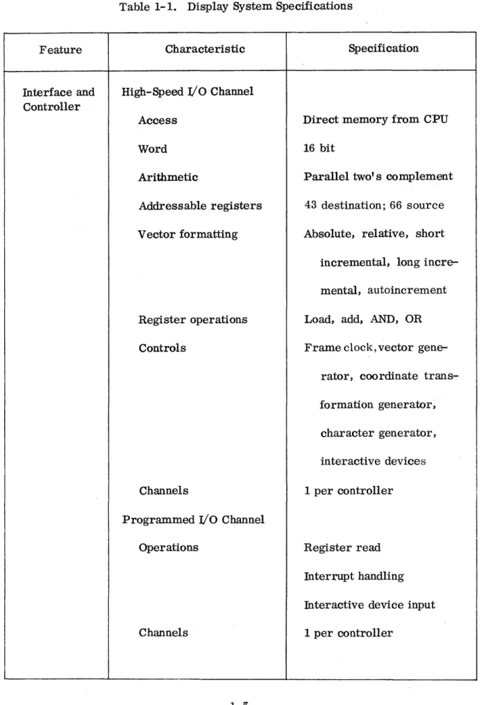
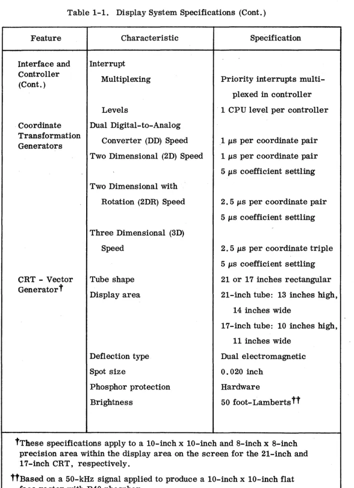
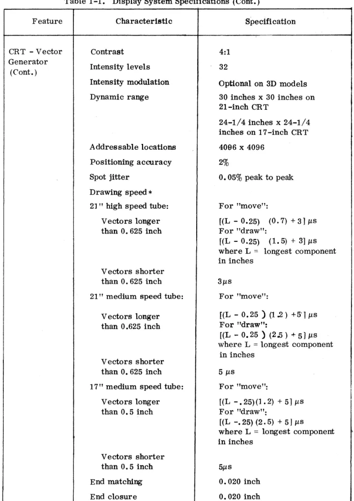
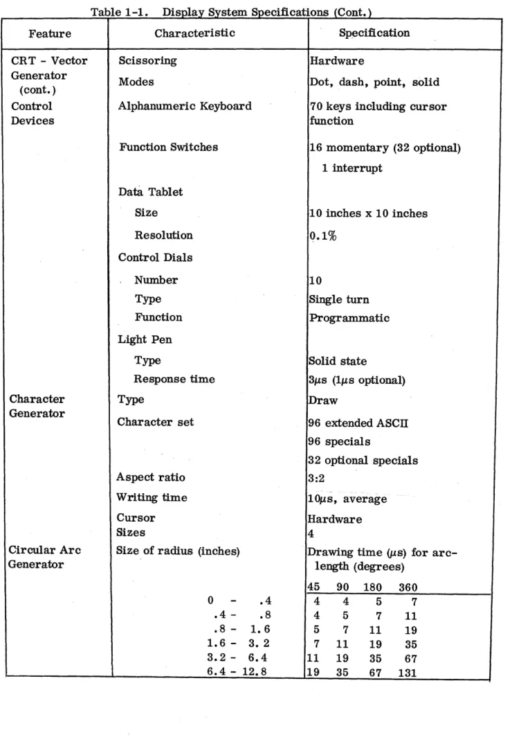
1.5 SYSTEM SPE CIFICATIONS
Table 1-1 lists the general specifications for the display system.
1. 6 DISPLAY PRINCIPLES
A cathode-ray tube display is a visible pattern on the face of a cathode-ray
tube formed by a fluorescent spot moving on a screen inside the tube. To
present a clear image, the pattern traced on the tube is repeated about 30 to
60 times a second. Any such repetition is called a "frame" and the
frequency at which it is generated is called the "frame rate".
The Vector General display uses the random scan method of controlling
the movement of the spot. Random scan co~trol involves steering the spot
in a straight line between two points on the display screen. A series of
these straight lines constitutes an image portion. All these directed lines
are defined between the previous position of the spot on the screen (the
starting point) and the position currently specified by the program (the
Table 1-1. Display System Specifications
Feature Characteristic Specification
Interface and High-Speed
I/o
Channel ControllerAccess Direct memory from CPU
Word 16 bit
Arithmetic Parallel two's complement
Addressable registers 43 destination; 66 source
Vector formatting Absolute, relative, short
incremental, long
incre-mental, autoincrement
Register operations Load, add, AND, OR
Controls Frame clock, vector
gene-rator, coordinate
trans-formation generator;
character generator,
interactive devices
Channels 1 per controller
Programmed
I/o
ChannelOperations Register read
Interrupt handling
Interactive device input
Table 1-1. Display System Specifications (Cont.)
Feature Characteristic Specification
Interface and Interrupt Controller
Multiplexing Priority interrupts multi-(Cont. )
plexed in controller
Levels 1 CPU level per controller
. Coordinate Dual Digital ... to-Analog Transformation
Converter (DD) Speed 1 IJ.s per coordinate pair Generators
Two Dimensional (2D) Speed 1IJ.s per coordinate pair
5 IJ.s coefficient settling
Two Dimensional with
Rotation (2DR) Speed 2.5 IJ.s per coordinate pair
5 IJ.s coefficient settling
Three Dimensional (3D)
Speed 2. 5 IJ.s per coordinate triple
5 IJ.s coefficient settling
CRT - Vector Tube shape 21 or 17 inches rectangular Generatort
Display area 21-inch tube: 13 inches high,
14 inches wide
17-inch tube: 10 inches high,
11 inches wide
Deflection type Dual electromagnetic
Spot size 0.020 inch
Phosphor protection Hardware
Brightness 50 foot- Lamberts tt
tThese specifications apply to a 10-inch x 10-inch and 8-inch x 8-inch precision area within the display area on the screen for the 21-inch and 17-inch CRT, respectively.
Table 1-1. Display System Specifications (Cont.)
Feature Characteristi c Specifi cation
CRT - Vector Contrast 4:1
Generator
Intensity levels 32
(Cont. )
Intensity modulation Optional on 3D models
Dynamic range 30 inches x 30 inches on
21-inch CRT
24-1/4 inches x 24-1/4 inches on 1 7 -inch CR T
Addressable locations 4096 x 4096
Positioning accuracy 2%
Spot jitter O. 05% peak to peak
Drawing speed *
2] " high speed tube: For "move":
Vectors longer [(L - 0.25) (0.7) + 3] J.Ls
than O. 625 inch For "draw":
f(L - 0.25) (1.5) + 3] J.Ls
where L = longest component
in inches Vectors shorter
than O. 625 inch 3J.Ls
21" medium speed tube: For "move":
V ectors longer [(L - 0.25 ) (1.2) +5'1 J.LS
than 0.625 inch For "draw":
[(L - 0.25) (2.5) +5JJ.LS
where L = longest component
in inches Vectors shorter
than O. 625 inch 5 J.Ls
17" medium speed tube: For "move":
Vectors longer [(L -.25)(1.2) + 5] J.Ls
than O. 5 inch For "draw":
[(L -.25) (2.5) + 5] J.Ls
where L = longest component
in inches
Vectors shorter
than O. 5 inch 5J.Ls
End matching 0.020 inch
End closure 0.020 inch
*Refer to Coordinate Transform Generator Specifications for array settling
Feature
CRT - Vector Generator (cont. ) Control Devices Character Generator Circular Arc Generator
Table 1-1. Display System Specifications (Cont.)
Characteristic
Scissoring
Modes
Alphanumeric Keyboard
Function Switches
Data Tablet
Size Resolution Control Dials Number Type Function Light Pen Type Response time Type
Character set
Aspect ratio
Writing time
Cursor Sizes
Size of radius (inches)
0
.4 .8 1.6 -
3.2-.4 .8 1.6 3. 2 6.4 6.4 - 12.8
Sp~cification
Hardware
Dot, dash, point, solid
70 keys including cursor function
16 momentary (32 optional)
1 interrupt
10 inches x 10 inches
Q.1%
10
Single turn
Programmatic
Solid state
31ls (IllS optional)
Draw
96 extended ASCII
96 specials
32 optional specials
3:2
lOllS, average
Hardware 4
Drawing time (J-ts) for arc-length (degrees)
45 90 180 360
4 4 5 7
4 5 7 11
5 7 11 19
7 11 19 35
11 19 35 67
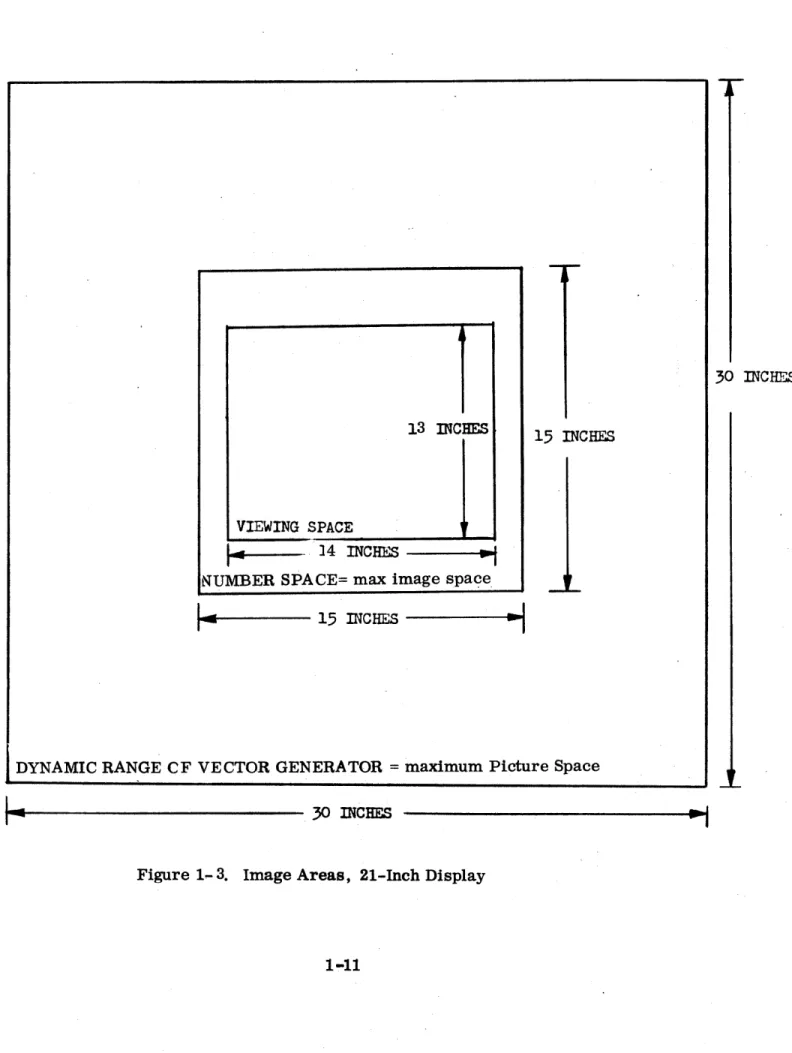
1.7 VISIBLE SPACE
That rectangular portion of the CRT which can be viewed by a user
will be called the ''Visible Space". The ''Visible Space" is limited by
an opaque mask with a rectangular cutout. See Figure 1-2.
The picture being generated is adjusted in size (scaled) to present the
desired output by means of two controls:
a. The program controlled "Picture Scale" (PS) register in the
transformation hardware (not available on standard DD system).
b. The manually adjustable "gain-controls" on the CRT deflection
hardware.
,The picture can be generated on a 'Picture Space" coordinate system
and scaled for viewing through the ''Visible Space".
The maximum size "Picture Space" is larger than the ''Visible Space".
This permits limited "zooming" but primarily allows fully vis ible
objects to be rotated and positione d to the extreme limits of the
''Visible Space" and yet draw any remaining visible portions without
distortion.
For the 21" CRT with the gain knobs at standard midrange calibrated
settings, the maximum "Picture Space" (over which the vector generator
accurately reproduces images) is a 30" x 30" plane of which the ''Visible
Space" (CRT screen visible throughmask) is a 13" by 14" rectangle in the
center. (See Figures 1-3 and 1-4.)
1.8 PICTURE SPACE
The hardware transformation options permit the coordinates defining an
image portion to be transformed prior to use for display generation.
The transformed coordinates used for display will describe a rotated and
translated instance of the image portion.
For the input coordinates (X, Y, Z) the output transformed X and Yare
used to generate the image portions' horizontal and vertical "Picture Space"
position respectively. Thus, the "Picture Space" is the X-Y projection
FULL
SCALE
NEGATIVE
FULL
SCALE
POSITIVE
y
X FULL
---..f.---
SCALEFULL SCALE
NmATIYE·
Figure 1-2. Visible Space
I
30 INCHF~
13 INCHES
15
INCHES
VIEWING SPACE
1,
I~
-
]4 INCHES -;NUMBER SPACE= max image spa<?e
""--~I----
15
mcHES
---I~
...
DYNAMIC RANGE CF VECTOR GENERATOR = maximum Picture Space
..
~---
30 mCHES12 IN~~ES 24 INCHES
. VIEW~ SPACE ~,
~., 11 INCHFS ---;.
NUMBER SPACE = !max Imagesplce
I_
12 IN~HES ~DYNAMIC RANGE. OF VECTOR GENEnATOR=maximum Picture S ace
r-
24 INCHES-i
If no transformation is performed, or for zero rotations, zero
displacements, and full scale size transformation, an image coordinate
(X, Y, Z) will correspond directly to the "Picture Space" (X, Y), with
positive X being horizontal towards the right of a viewer and positive Y
being vertical. For the 21" CRT with the gain knobs at the calibrated
settings, and the Picture Scale register (PS) set to maximum, a plus
full scale X image coordinate value transforms into an X Picture Space
coordinate value which corresponds to a horizontal displacement 7.5"
to the right of center or 1/2" to the right of the Vi sible Space. Similarly,
for no transformation and maximum Picture Scale (PS), a full scale Y
image coordinate value corresponds to a Picture Space position 7 .5" up
from the center.
To view a centered two-dimensional object defined over the entire
X-Y coordinate range (such as a page of text), the Picture Scale register
can be loaded with • 92 or the gain knobs turned down (as required on a
DD system). To view an entire centered rotated two-dimensional
object, an additional factor of 1 /~ picture scale is needed (not required
on DD system since it does not implement rotation). To view an erltire
centered three-dimensional object which is defined over the entire (X, Y, Z)
Image Space, an 1/1,'3 factor is needed to view the maximum length of
the projected diagonals of the Image Space.
Due to the larger range of the Picture Space over the Visible Space,
each of these views may be positioned out of the viewing area in any
direction without distorting any remaining visible portions. This capability
1.9 IMAGE SPACE
Prior to transformation and projection onto the Picture Space
for viewing through the V.isible Space, an object is defined in a
coordinate system which we will refer to 'as the Image Space. All
separately transformed objects of a displayed picture are defined in
their respective untransformed image spaces.
To exploit maximum use of transformation ra~es and· coordinate
resolution, all obje~s should be defined as large as possible in their
defining Image~_. Objects are defined primarily in terms of
generated visual. elements..v ectorsand Characters ~
In cases where effIcient interactive moditlcatton, dynamic model
presentatipn, or motion is desired, an object def1n1tion may cClltain
as elements "subimage calls" to 'generate transformed instances of
'other objects. In these cases, a composite Transformation of the
existing transform with that of the called instance must be loaded
into the hardware prior to processing. elements of the called object
definition for display generation~ This permits nesting of transfGrmable
object definitions which can be directly processed for display.
In addition to the programmable linear vectors, the display system
produces sets of AScn charactera generated independently of the
computer program by a character generator.
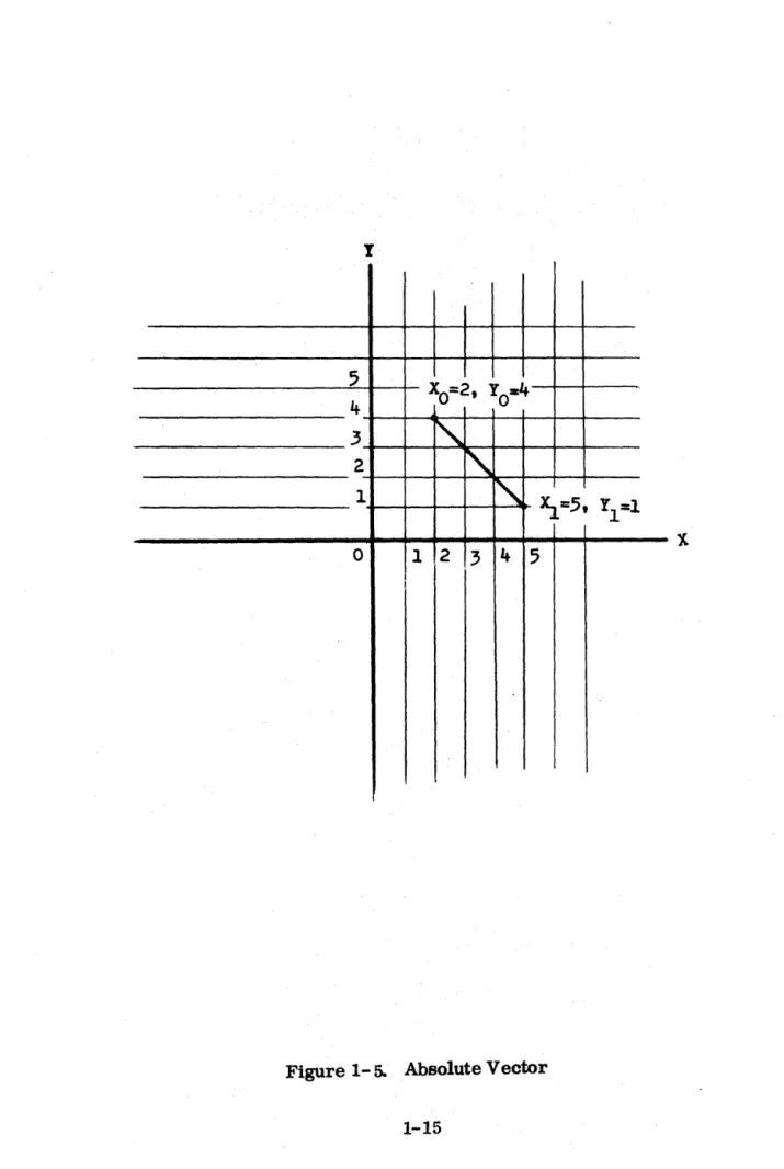
1.10 ABSOLUTE VECTORS'
The coordinates of absolute vectors are specified with respect to
the zero position in the center of the Image Space (or screen for
no transformations). Each new input data value is located directly on
t
5
Xo=2, YO-4 4
3
~
2
~
1
"
~=5, Yl=l0 1 2
3
45
I
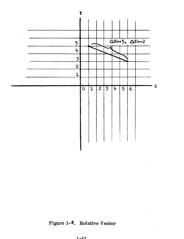
1.11 RELATIVE VECTORS
The end-point coordinates of a relative vector are located with respect
to the starting point coordinates. In other words, relative vector
data is specified in the form of increments that are added to or subtracted
from the previous coordinate values as sho~ in- Figure 1":~ An entire image construction can be positioned by drawing an initial absolute
vector and defining the rest of the image with relative vectors without
computing new end-point coordinates. This is an effective means of
(unscaled and unrotated) subimage calling when no transformation
hard-ware is available.
1.12 INCREMENTAL VECTORS
Incremen~al vectors are used when data storage is limited. Data increments
can be shorter than relative vector increments, with a resultant reduction
in the a~ount of data needed. Incremental vector display, therefore,
requires less data storage and improves performance by increas'tng the
rate of output and presentation. For coarse resolution, increments are
added to the high-order end of the previous coordinate values; for fine
resolution the increments are added to the low-order end.
1.13 AUTOINCREMENTING
The autoincrementing feature is used to step one coordinate at regular
intervals while the other coordinate is open to program change, as
shown in Figure 1:'" 7. This feature, used for graphs and similar
presentations, decreases memory requirements by 1/2.
1.14 TIffiEE-DIMENSIONAL DISPLAY
Three-dimensional presentation involves the addition of a third, or Z,
axis that is perpendicular to the face of the screen and intersects the
X and Y Picture Space axes at the zero point as shown in Figure 1. 8.
The Z axis represents depth into and out of the display screen. Option:
The illusion of depth may be achieved by varying the. light intensity of
the fluorescent spot in proportion to the value of the Z coordinat~. The intensity increases exponentially with the value from minus full-scale
to one-half full-scale intensity, with maximum intensity at the face
I
5
-
~ 6X=+5t 6Y=-2~
i'-~
I4 ~
...
~
~
3
2
1
I
i
0 1 2 3 4
5 6
x
J
y
I
______________
~v~~~+_~~~---X
--.,- " .EQUAL AX ADDED WITH EACH Y INCREMENT
full scale, the intensity is zero; that is, the spot is turned off or .
blanked.
1.15 CHARACTER GENERATION
The character generator accepts coded inputs fr~m the display
controller and produces text strings composed of AS'CII characters
and special characters. Characters are drawn on the screen as a
series of short vectors and curves. Unlike the vector generator,
however, the character draws are generated automatically by the
character generator each time a character code is received.
The program can select one of four character sizes and one of 16
intensity levels. A character scaling option is available for continuous
character sizes. This option allows Picture Scale and Coordinate Scale
to scale the image and characters proportionately. The program also
can specify whether the text lines are to be displayed horizontally on
the screen or are to be positioned as if on a page that has been rotated
900 counterclockwise. One of the characters is a cursor, which
differs from other displayed characters in that the character following
the cursor is drawn in the same place, without a column feed. This
feature permits the cursor to be moved over the screen as desired with
manual inputs. A hardware feature causes the cursor to blink twice per
second.
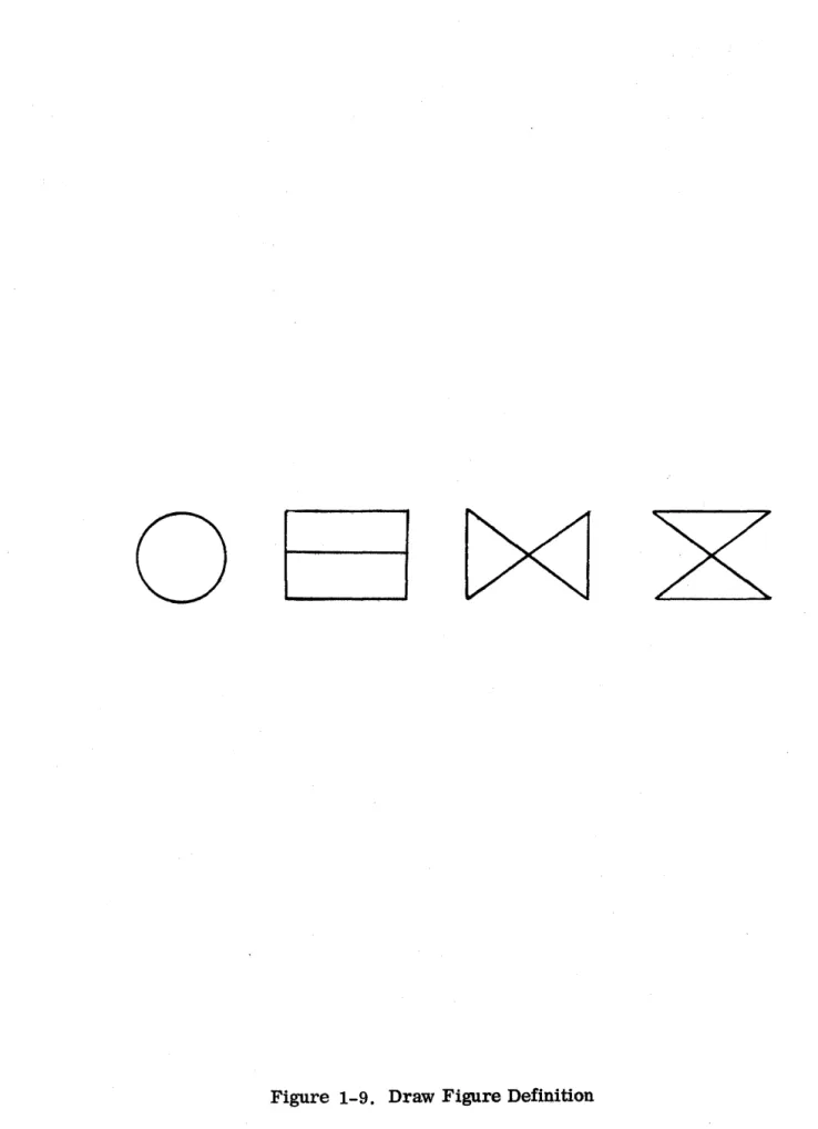
1.16 CHARACTER FORMATION
The character generator uses the function method of drawing characters,
rather than the raster or scanning method sometimes used in display
systems. The functional approach involves steering the fluorescent
spot through a sequence of strokes to create character shapes. The
characters are composed from a set of basic image elemerts, or draw
figures, as shown in Figure 1-9. Any ASCII character can be produced
in three draws or fewer, a draw being defined as all or a subset of one of
o
undisplayed sections of a character draw or from one character
to another.
1.17 CONTROL CHARACTERS
Twelve codes in the character set are used for control purposes
only and do not cause a display on the screen. The control
characters and their functions are as follows:
o
o
o
o
o
o
o
o
o
o
o
o
Null - Displays a blank in the corresponding char~cter position.
The spot is not stepped to the next character position
Delete - Same as Null
Backspace - Causes the spot to revert to the previous
character position
Line Feed - Causes the spot to move down to the corresponding
character position in the line below
Form Feed - Causes the spot to move to the position of the first
character on the page; that is, Line 1, Column 1
Carriage Return - Causes the spot to move to Column Position 1
on the line below
DCl - Causes the spot to move up to the corresponding character
position in the line above. Equivalent to backline operation
DC2 - Decreases the current character size by 1. This permits
sub- and superscript sizes to be embedded in the text.
DC3 - Increases the current character size by 1.
DC4 - Terminates the data associated with a character generation
display instruction.
Horizontal Tab - Resets the current column position to "horizontal
center" and increases the current line position by one line.
Vertical Tab - Instates current character positioning to "horizontal
The first character in a string always starts at the location
defined by the current X and Y coordinates.
1. 18 INTENSITY LEVE LS
For two-dimensional ,display, 32 constant intensity levels can
be selected by the program. 'These intenSities can be applied
to vectors and charact ers.
The spot can be blanked as desired under program control during
vector display.
Automatic blanking is an effect in the following operations:
o Presenting dashed or dotted lines between two positions on the
display screen - The spot is alternately blanked and unblanked
at appropriate intervals while a vector is drawn. The start
and end of a vector are always unblanked.
o Placing a point at any given position. The spot is blanked
while moving from one location on the screen to another
and briefly unblanked at the end of the vector to form a point.
1.19 IMAGE TRANSFORMATION
Image transformation is an optional hardware feature that involves
scaling, rotation, and position change (translation). The DD
system has no transformation.' The 2D system implements scaling
and translation only. The 2DR system implements scaling and
translation with rotation around the Z axis. The 3D' system contains
all the image transformation features, including rotation around
any axis.
1.20 SCALING
The scaling operation consists of changing the size of an image
portion by multiplying each end-point coordinate by the desired
scale factor before processing. The scale factor is specified by
the program, and the current scale factor is maintained in a
hardware register to be multiplied by the X, y, and Z coordinate
ORIGINAL
IMAGE
Figure 1-10. Scaling
SCALED
1.21 ROTATION
An image portion can be rotated around any of its axes by using the
optional hardware rotation matrix. The desired rotation is specified
by loading direction cosines, or the sums of triple products of
trigonometric functions in the more 'elaborate cases, into the rotation
matrix, which has registers for each coordinate axis •. The rotated
image instance is automatically defined by a linear transformation of
the coordinates of the unrotated master, using the direction cosines or
the triple products which represent the angles between the coordinate
axes of the two images. The 2D system rotation matrix
contains only the registers necessary to rotate the X and Y coordinates
around the Z axis. An example of rotation is shown in Figure 1-11.
1.22 TRANSLATION
An arbitrary image may be positioned anywhere in 3 -di~ensional
space by adding a value to each of the scaled and rotated coordinate values every time an end point is specified. The value added must
be constant for each coordinate to maintain the original image
configuration. An example of translation is shown in Figure 1-12.
1.23 PICTURE TRANSFORMATION
When a 3-dimensional image made up of characters and vectors has
been transformed to obtain the desired scale, rotation, and translation,
a 2-dimensional view can be extracted and presented as a picture on
the display screen. The two operations involved in this final presentation
are picture scaling, to change the size of the transformed image, and
intensity modulation (optional) to give a 3-dimensional depth cueing effect.
1.24 PICTURE SCALING
A hardware register is provided to hold a va me that s cales all the
final transformed X and Y coordim te values. This scaling is used primarily to reduce full-scale, rotated, 3-dimensional images so
that they fit into the display screen while permitting untransformed
I ,
I /
ORIGINAL ROTATED
IMAGE IMAGE
ORIGINAL
IMAGE
Figure 1-12. Translation
TRANSLATED
1. 25 INTENSITY MODULATION
Intensity modlJ.lation is the name given to the depth cueing transformation
used in all 3D systems, that shades the intensity of the displayed picture
to give a 3-dimensional effect. The value of the transformed Z coordinate
is used to represent depth into and out of the display screen, and therefore,
controls spot intensity.
The picture transformation hardware includes the facility to blank any
part of the picture that falls out of the screen towards the viewer. The
cutoff plane can be moved toward or away from the viewer by the program
so that sectional views may be obtained. This feature is an advantage
when it is desirable to remove parts of cluttered images for clearer
visibility. Since there is also a cutoff at the rear of the image, this
transformation can be used to hide certain lines at the back of a 3 ... dimensional
SECTION II
SYSTEM ORGANIZATION
2.1 INTRODUCTION
This section contains a functional description of the system
components, including the hardware registers. The optional
control devices that may be used with the system are also des cribed.
2.2 FUNCTIONAL DESCRIPTION
A functional block diagram of the CRT Display System showing the
basic op~rational elements and data flow through these elements
is shown in Figure 2-1. The basic elements can be grouped into
the following functional sections: vector coordinate registers;
coordinate scaling and displacement option; rotation option; picture
control option; character generator; vector generator; cathode ray
tube; and input/output facility. The optional control devices are not
shown in the block diagram but also are basic to the system if included.
2.3 VECTOR COORDINATES
The display system maintains the coordinates of the current position of
the fluorescent spot in the 12-bit X- and Y -registers, with the
inclusion of a 12-bit Z-register for the 3D option. These registers
hold the X, Y, and Z coordinates respectively. The values in these
registers are updated as new coordinate values are received on the
data channel.
When relative vectors are specified, a coordinate increment is received
on the data channel and added to the current coordinate value. The
sum is then loaded into the proper register. If incremental vectors
are specified, the increment is added to either the high-order or
low-order end of the current coordinate value, depending on the scale
specified by the program.
2.4 COORDINATE SCALE OPTION
NOTE: DOES NOT REFLECT HAR!)'t:t..?E IMPLEMENTATION CHARACTER GENERATOR FONT X Y X CHARACTER SCALE OPTION
MINOR X
MINOR Y
1
VECTOR+
C.R.T. DISPLAY SCOPE
y SCALE Fd'---R-O-T-A-T-E-'='---D-IS-P-L-A-C-E'F== PICTURE
~
:GENERATOR1:
-~ HORIZONTAL
F*= =~ VERTICAL
=~ INTENSITY
Z '-m=,I,1 = r=TRANSFORMlj
. r===I!"L---.-~r- F== Ftffta Z
11
Jt I
t~===;!'
"~
1
Iii
VMCHAR W 5Z
Jt
II
Iiii
DMA L:====================~=========t==~====~====~~==:====~~~========~=======;~"H;F=========~r===========t===~~OF
OUTPUT
I
~ADDERll
t!<l=iS,=="P±"",=LF=#==~
I
~_....::.J~_-,
I!H
Iu
':
I'-~ rII> I NTERUPT
I
INCREMEN T CONTROL REGISTERS WCRRESET j WORD
START 1 COUNT
STOP f MCR MODE CONTROL
~
1
I
I TRANSFORMATION I':!, I I PERIPHERAL j
R~P, V!F ~: REGISTERS I/O REGISTERS
!
'!' 'I' HT
r '
;---,-;-VT COORCDTtfATE pJ I '! TRANSFORMED:~ 1<l:====4==Xil"=!t.L~
SCALE
I
COORDINATES P ZR~!~~II~N : ' DIAL
RIIR RI2R RI3R F= ~ INPUT
R21 R R22R R23R II
R31 R R32R R33R :1
ADC
01 THRU 010 1<:====+====4=====91 DIALS
'I
QJ
DXRrr"
IMAGE d , X DISPLACEMENT f==
GENERATION i:
I
JOYSTICK XL
REGISTERS
I
Y DIS~LY:CEMENTr'=+= ~g~~~:~~ ~r
.~-= ~=~~~'F===~===9{JOYSTlCKI
COOR~INATJ
j
DZR L :i~=T:;:A=B=L=E:::;T=X==~Lkf~-;:;::::::::;:=t====:flr;eliTl
Z DISPLACEMENT r ~ TABLE~ ~ t=- .--t TABLET
ICOOR~NATI~} PSR L~ IS~~T~Er
PICTURE SCALE r ~
{
= :::
==-
INMRI
ICOORoiNATJ~l ~ 'NTENS,i~~FFSETt~
I
KEYBOARD~~t=
r---J .. _ .. IK_E_Y_B_O_A_R ... OPRo~~2MED AKW = ' = ~
<J=K
IN~~~~~N-~ IINTENS~~~ SCALE rf==== F~~~/~~N}: = = , ~~~~F==o=~"~~~""1F~\~fl~~O~INPUT ----t
OUTPUT SAR U Jl U U
c=~~=;==~~C~O~N~T~EN~T~S~O~F~RE~G~I~ST~,E~R~D~E~SI~GNN~ATfiE~O~B~Y=l============~==:==~========================================~ ----~ - =.~ L~~~T PROGRAM
I/O REGISTERS
l
CURRENT SOURCE ADDRESS (SARlFIGURE
DISPLAY FUNCTIONAL BLOCK DIAGRAM
scale factor is loaded by the program into a 12-bit coordinate
scale register. This number is multiplied by the current
coordinate values from the X, Y, and Z coordinate registers.
Character s also are scaled in proportion to the rest of the
image with the character scale option.
2.5 ROTATION OPTION
To rotate the image around any of the three axes, trigonometric
values are loaded into rotation matrix registers RIIR through R33R.
Registers R13R, R31R, R32R, R23R, and R33R are used only for
3D rotation. If the three scaled input coordinates are defined as
XO' YO' and Z 0 and the three computed outputs are Xl' Y l' and Zl' the following computation is performed:
Xl = RIIR • XO'+ R12R • YO + R13R • Zo
Yl =R21R. • Xo +R22R • YO + R23R • Zo
Zl = R31R .. Xo + R32R • ~ + R 33R • Zo
The coefficients of an object after rotation may be continuously
computed from the coordinates of the unrotated master by loading
coefficients defining the desired rotation into registers RIIR
Figure 2-2 illustrates the effect on a point of two-dimensional rotation about
the Z axis by the angle (). The coordinates of the rotated point in terms of its
original unrotated coordinates are as follows:
X' = X cos (J + Y sin ()
Y' = X(-sin
i+
Y cos (jZ' = Z
The values of RII through R33 that would perform the illustrated rotation are
as follows: RII = R22
=
cose
R12
=
sin :6R21 = -sin G
R33 = I
Rl3
=
R 23=
R31=
R32=
02.6 DISPLACEMENT VECTOR OPTION
The displacement vector option performs the translation function in the image
transformation feature by moving the image intact along any of the three axes.
The X-displacement, Y-displacement, and Z-displacement registers are used
to implement this feature. A displacement constant loaded by the program into any
one of these registers is added to the associated rotated coordinate values being
maintained by the rotation, scale, and coordinate registers. The result is a
ROTATED POINT
=
(Px Py)=
(Px"
Py')X'
PX'~le
~~"A. COS
e
X
---~~~~~---~---9
PX' =
Px
COS 9 + Py SIN 9Py ' =
Px
SIN 9 + Py COS 9loaded. An example of the displacement operation in an X, Y plane is shown in
Figure 2-3. The X displacement register contains a 2 and the Y displacement
register contains a 3. The value 2 is added to each X coordinate and the value 3
is added to each Y coordinate as follows:
register contains a 3. The value 2 is added to each X coordinate and the value 3
is added to each Y coordinate as follows:
Original Position
X =2
o
y = 2
o
x
= 31
Y = 1
1
X= 5
2 Y = 2
2
x
= 63 Y = 1
3
2.7 PICTURE CONTROL OPTION
New Position
X =2+2=4
o
y =2+3=5
o
X =3+2=5
1
Y =1+3=4
1
X =5+2=7
2
Y =2+3=5
2
X =6+2=8
3
Y =1+3=4
3
The picture control option is used for picture transformation after the
trans-formation of individual images on the screen has been completed. The registers
used for this feature are the 12-bit intensity offset register, the 12-bit
intensity scale register, and the 12-bit picture scale register. The
-"8
-7
-6
- 5
- - 4
- - 3
, - - - 2
- - - 1
DXR
=
2DYR = ,
y
TRANSLATED IMAGE
:'\.
. /V
~
-r--XO' YO ~X2' Y2
~lX
~
X
3'
Y,_O~, Y1
o
1 1 I2
3 4 5 6 7
8
RIGINAL IMAGE
x
x,
Y, and Z coordinates to establish the final picture size. This scaling applies also to characters in the picture, with the char-scale option.In a two-dimensional system, the 12-bit intensity offset register (lOR) is loaded
by the program to specify 1 of 32 intensity levels. Only the high-order five bits
of the register are used for this purpose. The intensity levels apply to characters
as well as to two-dimensional vectors. Full scale in the intensity offset register
designates maximum intensity, and the intensity decreases exponentially as the
value decreases to minus full scale.
In a three-dimensional system with the Intensity Modulation option
t he intensity scale register is used in conjunction with thE'
.. ..--... "-.. - , , - . , ...
intensity offset register to provide depth cueing, or shading of the
intensity of the picture according to the value of the
Z
coordinate. The intensity of the spot at any instant is represented by the following equation:k (Z' - 1)
if IS sign = 0: I = Imax. e·
else if ISsign = 1:
where:
, k Z'
I
=
I .-e max=0
Z'
=
IS*
z ·
+ 10 mag rotatedwhen Z' ~ 0
when Z' > 0
This equation provides for exponential shading of the intensity along the length of
vectors drawn between coordinates of different intensity values. A "screen-cutoff" can
be imposed at Z' = 0 by setting the sign bit of ISR, then if Z is greater than
1 - 2 * lOR
The intensity cutoff plane is established by the value in the intensity offset
register. Within the depth range of an image, the intensity is blanked between
the viewer and the screen. The intensity is at its maximum at the face of the
screen and decreases exponentially with decreasing values of Z toward the back
of the image. Figure 2-4 shows a simplified cross section of a CRT with a
three-dimensional image in two different poaitions with respect to the intensity
cutoff plane. As the value in the intensity offset register is changed, the image
moves forward or backward through the intensity range, to vary the section that
is intensified and the part that is blanked out.
The intensity range, or apparent depth of the image, is determined by the value
in the intensity scale register. If the value is 1, the maximum intensity range
is achieved. If the value is 0, the intensity is constant and the image has no
depth-cueing. Figure 2-5 shows how a variation in intensity scale changes the
depth of the image.
2.8 VECTOR GENERATOR
The vector generator accepts as inputs the transformed coordinate values and the
display controller instruction. Two outputs from the vector generator move the
floures-ent spot in a horizontal and vertical direction on the screen. A third output varies
the intensity of the display. Programmed vector mode information is stored in
,"",
INT.i·~NSITY. ----~
Low 10 High 10 dim bright
lOR VARIATION
NAXlMUM
rINTENSTrY
OUTSIDE, BLANKED
\~
R
-~ ~?
ZERO INTENSrry
Large ISR:
Back Much Dimmer
Than Front Imax
l'
FRONT BRIGHT
Small ISR:
AI.,L 'NEA..'qLY THE
SAME BRIGHrN'"'.uSS
(.
~
Imax
Figure 2-5. Effect of Intensity Scale Variation
specify lines, dashes, dots, or points. Vector operation information, also
stored in the vector generator, determines whether the spot on the CR Twill
draw a vector, move from one location to another without drawing a vector,
or remain stationary while new current coordinates are being received from
the computer.
2.9 CHARACTER GENERATOR
The character generator interprets character codes received from the
display controller and provides small X- and y'-axis deflection inputs to
the cathode ray tube.
Inputs to the character generator are in the form of a stream of ASCII codes
and information specifying size and the character fonts.
Character positioning signals from the character generator are sent to
the adder for combination with the current X and y coordinates to locate
the starting point for each new character. Size information is decoded to
control the minor deflection signals in four different ways to produce the
four character sizes. Two-dimensional scaling inputs from the coordinate
scale option and from the picture scale control option are used in the
character generator so that character strings may be scaled and translated
with their associated picture structures; that is, images and their labels
may be transformed as a single construct.
The dimensions for character generator outputs in Number Space units
are given in Figure 2-6.
The following picture shows the standard character set font. The codes for
each character can be found in Appendix A.
2.10 CmCULAR ARC GENERATOR
The arc generator accepts as inputs the transformed coordinate values
and the display controller instruction. Two outputs from the arc generator
move the fluorescent spot in a horizontal and vertical direction on the screen.
11
1
tt$%~
1 ( )
*+
J --0/0123456789:
~
<:=>?
~ABCDEFGHIJKLMNOPQRSTUV~XYZ[\J/'-_
'abcdef gh
i
jk I ffiYlopqr
stuvwx~z{
\
}
rvo
t
110£
v
J
1/
c: ::> 10 : L=
~
-,
0
t
\101:-
1\d
L
uno
X~
;c
~
CD00
\j _
~ ~
:3
<P
0 T
~
0 1\ / \illJY\
0
IT ()
J>
I
elf /\
I
r _ L~
f- - 0LINES
PER
PAGE
COLSPACEl [
4
rlIr
r -,
LINE
I
[l,r;}
I
FEED
,-_~J
t
Character Square: Centered on major (X, Y) Coordinate Point.
Char ac ter Height
r
l
R-',
.
.•..•. LLI_.!
.. , _____
J
_
f
~. ~~
Character WidthI
D
---D
Char. Size Code SO Sl S2 S3 Char. Size Code SO Sl S2 S3 \.
---
---~)
VCOLUMNS PER LINE
(In Decimal)
----~~----~~~--- Col. Space
Cola/Line Lines/Page Size
120 80 60' 32
60 .42
40 62
30 104
16 200
Character Square (Octal)
55~1/3 X 55-1/3
102-2/3 X 102-2/3
132-2/3 X 132-2/3 252-2/3 X 252-2/3
{In Octal~
Linefeed Size 104 144 210 400
Character Char.
Height Width
42 26-213
62 41-1/3
104 55-1/3
The generated arcs are coded anywhere within any of the following
types of vector lists:
Vector Relative
Vector Relative Auto-X Vector Relative Auto-Y Vector Relative Auto-Z Vector Absolute
Vector Absolute Auto-X Vector Absolute Auto-Y Vector Absolute Auto-Z
Thus, arcs can have line texture (solid, dotted, or dashed) and can be
mixed with vectors.
The arc generator draws arcs from the initial beam position to the given
end-point (omitted for 3600 circle) about the following center-point.
The center and endpoints of the arcs are properly transformed in both two
and three space, but the arcs are drawn in a plane parallel to the screen
(as are characters)~
Thus, all arcs are properly transformed by DD, 2D, and 2DR systems,
and only rotatable about Z in 3D systems.
2.11 CATHODE RAY TUBE
The three inputs to the CR T are horizontal and vertical deflection, to
control the movement of the fluorescent spot, and intensity, to control
the brightness. The intensity input is received as two signals. One is an
intensity level signal, and the other is an on/off blanking signal. The
major deflection signals are received from the vector generator, and
minor deflection inputs from the character generator are superimposed.
2.12 OPTIONAL CONTROL DEVICES
The functions of the interactive control devices that may be used with the
2.13 ALPHANUMERIC KEYBOARD
The alphanumeric keyboard is used as en entry device for manual input
to the display system. Pressing a key on the keyboard enters an eight-bit
character code into the keyboard register in the display controller and
sets bit 12 of the priority interrupt request register (MEK) to indicate a
keyboard interrupt condition. The character entered in the keyboard
register does not directly affect the display on the screen. The program
can read the keyboard register contents and use the information in its
operation. One function of the program may be to place the character into
a display list being presented on the screen. Holding any key down will
maintain the correct code in the keyboard register and, after an initial delay,
will repetitively raise the MEK (keyboard interrupt requee:) to repeat any
character. Appendix A lists the codes generated by the keyboard for
shifted and unshifted key combinations. The following diagram gives the
keyboard layout:
2. 14 LIGHTED FUNCTION SWITCHES WITH MANUAL INTERRUPT
,2.15
This device contains 16 or 32 function switches plus a manual interrupt
switch. The function switch register in the display controller has one
bit corresponding to each function switch; that
is,
bit 0, for function switch 1, bit 1 for function switch 2, and so on through bit 15 for function switch 16. While any function switch is depressed, the corresponding bit in thefunction switch register is set. The computer can then read the contents
of the register and use them.
The manual interrupt switch can be used to cause an interrupt. This
feature allows the OlE rator to intercept the program at any desired point.
When the manual interrupt switch is pressed, bit 13 of the priority interrupt
request register (MES) is set to indicate a manual interrupt condition.
The first 8 bits of the first two output-register addresses control the
16 function switch lights. Sending ones will light the c.0rresponding light,
and zeroes turn them off. Note: as with all dispt'ay regis~ers, ANDing
and .ORing operations permit independent manipulati?n··of,fields.
JOySTICK'
Tile joystick is a mechanical device used to enter coordinate values in
the 12-bit joystick X, Y, and Z input registers. A forward or backward
motion of the joystick increases or reduces the value for the joystick
Y -input· register. A motion from side to side changes the joystick X -input value. The joystick Z-input value are decreased or increased when the
joystick is twisted in a clockwise or counterclockwise direction. A 11 three
motions have a spring return to an adjustable null center position. These
input registers may be read by the computer, and, if desired, the joystick
values may be added into the X, Y, and Z displacement registers to move
2.16 LIGHT PEN
The light pen is used to point at an element of a display or to create
information by "drawing" on the display. The light pen, a wand containing
a photocell, is held OVt-r the face of the CRT by the viewer. When the
light pen is held over a. liile or point on the display, bit 10 of the priority
interrupt request register (MEP) is set to indicate a light pen interrupt
condition. If the light pen switch is activated, bit 15 of the
pm
register is set. The light pen may be used to identify an existing element of adisplay or to introduce new information into the system. In the latter
case, a smal11ight pattern (tracking cross) is generated on the screen by
the program and acquired by the light pen. The position of the pen in the
pattern can be continuously computed from the pen's response to the
pattern, and the coordinates can be maintained by the computer program.
It should be notedthat when reading the display list word count register
to identify the word that caused a pen halt, that·the count can be further
resolved to the halfword field during packed-data and character modes
via tbe Pen-byte-resolution (PB) field of the mode register. A hardware
delay feature that inhibits proceeding to a new instruction until the light
pen has had a chance to respond to the last drawis included in the display
controller and can be useful for preciSion pen pOSition in data list
identification.
2.17 -DATA TABLET
The data tablet is a graphic input device with an X-Y coordinate grid which
may be used corresponding to the grid on the CRT screen. Information is
entered through the data tablet with a stylUS. The tablet senses the location
of the stylus on the grid and loads the X and Y coordinates of the stylus
location into the tablet X and tablet Y registers whenever a PIO operation is
performed. When the stylus is pressed down on the tablet, a switch is
2.18 CONTROL DIALS
Ten optional control dials may be used to send digital numerical information
to the computer for any purpose specified by the program. Each dial is
associated with a 12-bit dial input register in the display controller. As
the dial is turned, the corresponding register will read back a succession
of numbers. These numbers can be read by the computer at any time.
2.19 PROGRAMMED INPUT/OUTPUT CHANNEL
The display is stopped or started and interrupts may be acknowledged by
the computer over the programmed input/output channel. This channel
also is used to read the contents of the display registers. A source
address is sent to the controller to specify which register is to be read
first. If further reading is programmed, the contents of other registers
are read in numerical order by adding one to the source address each time
a register is read.
2.20 INTERRUPT CHANNEL
A bit in the priority interrupt register is set when an interrupt condition
is detected. If the corresponding enable bit is set in the mode control
SECTION III
DISPLAY SYSTEM PROGRAMMING
3.1 INTRODUCTION
This section contains a discussion of the priority interrupt system as
well as a functional description of each display instruction with its
applicable data lists. The display system registers available to the
programmer are des cribed, and des criptions of the various word
formats used in programming the Display System are given.
Operation of the display system consists of processing data words
in
accordance with their associated instructi6ns~---Ifi.strticti6ns that draw
lines or-textstringspro-cess data words· givi1lg the end--point coordinates
of the lines or. character __ codes of th~ text._R~g~_~ter_g~stinatj.on instructions
are followed by data words containing the information tc;> be· acted upon and
__ 1,.-.
written into the addressed register.
3.2 PROGRAMMATIC INTERFACE
The interface between the display system and the computer consists of:
,a. A single programmed I/O ch8lUlel
b. A single priority interrupt level
c. A single direct memory access channel
The display presented to the viewer is sent by means of a direct memory
access (DMA) block transfer data channel. A computer program must
service the DMA to output the lists of display instructions.
Programmatic I/O operations are used by computer programs to control
the display system, read its status, and communicate with any peripheral
The interrupt is used to support the peripheral I/O devices and to
execute . programs required by the display lists being output. The use
of the interrupt system is further elaborated in Paragraph 3.9.
3.3 DISPLAY SYSTEM REGISTERS
The display system contains registers directly addressable by the
program. Registers with DAR addresses (Figure 3-1) may be changed
by display instructions and are therefore referred to as destination
registers. All registers with SAR addresses (FigUre 3-1) may be input
by a program with a programmed I/O read operation and are th erefore
referred to as source registers. The address of a register to be changed
by a display instruction is held in a nonaccessible destination address
register (DAR), and the address of the next register to be read via
programmed input is held in the source address register (SAR).
3.4 DESTINATION REGISTERS
Registers with listed DAR addresses are directly addressable as destination
registers, and their contents can be changed by register setting display
instructions. Figure 3-1 illustrates the registers and gives the register
names and their mnemonics.
Register 6 is the instruction register (ffi) which holds the current display instruction of the list being processed from DMA output. Register 7
is the word count register (W CR) and is res et to zero each time
the data channel is restarted. As each display list word is
transmitted for display processing, the word count is increased by one
2 D 2 D 3 D DR D
Function Switch #1 FS Lamp #1 Keyboard #1 FS Lamp #1 Tablet X #1 Tablet Y #1
x x x x Name & Interrupt Request x x x x Mode Control x x x x Display Instruction x x x x Word Count x x x x X Coordinate x x x x Y Coordinate Z Coordinate x x x x Auto Increment Constant x x x x Dimming Control
Depth Cueing Control Memory Address* Stack Pointer" Temp. General x x x Picture Scale x x x x Name
x x x Coordinate Scale x x x X Displacement x x x Y Displacement x Z Displacement Rotation Matrix
Window Mode Control Window Boundry X High
X Low Y High Y Low Z High Z Low'
Multi-Device Interrupt Multi-Device Mpde Cont.
Function Switch if2 F S Lamp if2 Keyboard if2 F S Lamp if2
Function Switch if3 F S Lamp #3 Keyboard if3 FS Lamp #3
Function SWitch if4 F S Lamp if4 Keyboard if4 F S Lamp #4
Transformed X Transformed Y Transformed Z Joystick X Joystick Y Joystick Z Dials
Intersection Coord, X Y Z DAR F81 LTIH KBI LTIL TIX T1Y NMR, pm MCR m WCR XR YR
ZR 10 Am 11 lOR 12 ISR 13 MAR 14 SPR 15 TGR 16 PSR 17 NMR 18 CSR 19 DXR 20 DYR 21 DZR 22 RHR 23 Rl2R 24 Rl3R 25 R21R 26 R22R 27 R23R 28 R31R 29 R32R 30 R33R 31 WMCR 32
XHR 33
HLR 34 YHR 35 YLR 36 ZHR 37 ZLR 38 39 40 41 42 43 44 45 DPm 46 DMCR 47 48 49 50 51 FS2
LT2H 52 KB2
LT2L 53
FS3
LT3H 56 KB3
LT3L 57
FS4
LT4H 60 KB4
LT4L 61
PX PY PZ JX JY JZ 01 D2 D3 D4 D5 D6 D7 D8 D9 010 ex CY CZ DAR SAR DD 2D
Destination Address for R~gister Change Instruction Source Address for Programmed Inputs
2DR 3D
Dual DAC System 2 Dimensional System
2 Dimensional with Rotation Display System 3 Dimensional System
REGISTER BIT POSITIONS
10 11 12 13 14 15
SO S1 S2 S3 S4 S5 S6 87 S8 I S9 I SlO I SI1 S12 I Sl3 I S14 I S15 LO Ll L2 L3' L4 L5 L6 L7
KO Kl K2 K3' K4 K5 K6 K7 L8 L9 LlO L11r L12 L13 L14 L15
TXO TX1 TX2 TX31 TX4 TX5 TX6 TX7 TX8' TX9' [:]L TYO TY1 TY2 TY3 TY4 TY5 TY6 TY7 TY8' TY9'
NAME PID' PIC , PIP , PIT PIK 'PIS , PIW' SPJ MEDI MECI MEP 1 MET! MEKIMES MDB'MPH MS1 , MS2 , MS3 , MS4' re , MDRI MDW
P INST I ADDR MODE MODIFIERS
+ +
!
+ +
DISPLACEMENT PAGE J DISPLACEMENT PAGE
,
+
,
+ I
,
NAME
,
+ ! + + ! -+ + + ! ! ! !
MBI MBO MEl MEO MWHI MWp! PWI PWC PXHI PXL I PYH I PYL PZHI PZL!
+ + + ! -!
JPIP2 PIP:! J1:'IPt jP~2 lPIK3 jPIK4 JPl!:i2 Pl!:i(j jPl!:i4 , ,
,
, SP2, SP3 LSP4 MEP2 ,MEKa ~Vl"''''' 11vl"'''''1,
, , I ISO S1 I 82 I S3 I S4 I S5 I S6 I S7 I S8 I S9 I S10 I S11 I S12 I S13 1 S14 1 S15 LO Ll I L2 I L3 I L4 I L5 I L6 L7 ,
KO Kl ~ K2 I K3 I K4 I K5L K6 K7 I L8 L9 I LIO I LU I L12 I Ll3 I L14 L15 I
so SJ I 82 I S3 I S4 , S5 I S6 S7 I S8 I S9 ,S10 I S11 ,S12 I S13 I S14 I S15 LO Ll 'I L2 I L3 , L4 I L5 I L6 L7 I
KO Kl I K2 I K3 I K4 I K5 I K6 I K7 I L8 L9 L LlO L L11 L Ll21 LIS I Ll4 L15 ,
so Sl I 82 I S3 I 84 I S5 , 86 I 87 IS8 I S9 I 810 I Stl IS12 IS13 I S14 I S15 LO L.t L L2 L L3 1 L41 L5 L6 'L7 I
KO Kl jJ:2 I K3 I K41 K5 K6 K7
L8 Lt. I t.1O I Lll 1 LIZI L13 L141Ll5L
.:!: .:!: .:!: .:!: -+ + + + + + ! + + + + +
Figure 3-1
3.5 SOURCE REGISTERS
All SAR registers may beJread by means of a programmed input read
operation. The register to be read must first be selected by setting its
address in the source address register (SAR) through a programmed
output write. After the designated register is read, the SAR is stepped by
one, allowing successive registers to be read in sequence by successive
programmed read operations. Registers which correspond to analog
values (i. e., SAR = 64 - 82) will initiate an analog-to-digital conversion
operation to obtain the input value. The conversion is automatically
initiated whenever SAR addresses· a new analog input value.
Figure 3-1 gives the source and destination addresses for all display
system registers and gives the regis ter names and their nmemonics.
3.6 PROGRAMMED I/O
There are . two programmed I/O operations: Programmed input read and
programmed output write.
Programmed input is used by any computer program to read display state
or status, transform or coordinate values, peripheral inputs, etc. The
format of the word input matches that of the display register being read.
For example, if the SAR specifies source register 4 (pm), then bits 8
through 13 of the word read via programmed input constitute the interrupt
. request bits and are set by the individual device requesting an interrupt.
Bit positions 0 through 7 of the input word can be used as a name field to
identify interrupt·req~irements as on different pen-sensitive image
o
1 2 3 4 5 6 7 8 9 10 11 12 13 14 15I
NamePIO Sample Input of FIR
Bit positions 0 through 5 of the word written via programmed output are inter~
rupt acknowledge bits. These are used to reset the applicable interrupt request
bit in the interrupt condition sense register (PIR) after the requested interrupt
has been pro,cessed. Bit positions 6 and 7 control the starting and stopping of
the display. Bit positions 9 through 15 of the output word indicate which source
register is to be read next on the programmed input. The word format for
pro-grammed output words is shown in the following diagram.
o
1 2 3 4 5 6 7 8 9 10 11 12 13 14 15I
j 1 1 1 1Interrupt
Acknowl.d •• SAR
Programmed Output Write Format
3. 7 PROGRAMMED OUTPUT
The programmed output write word is sent on the programmed I/O channel to
the interrupt acknowledge and source address register. Bits 0 through 5, the
interrupt acknowledge field, reset interrupt request bits in the priority
inter-rupt request register (PIR). Bit 7 of the acknowledge field is used to cl~ar and
restart the display system processing of an instruction/data stream. Bit 6 is
The programmed write output word can perform the following three functions:
o Acknowledge and release any enabled active requested interrupts which
are pending, and restart the display if it was waiting
o Clear current display activities and start or stop display processing
o Designate the initial display register for subsequent programmed read
operations
The programmed output write word is shown in the following diagram.
o
1 2 3 4 5 6 7 8 9 10 11 12 13 14 15PO Acknowledge Display Interrupt (AKD)
Pl Acknowledge Frame Clock Interrupt (AKC)
P2 Acknowledge Light Pen Interrupt (AKP) (and continue if waiting)
P3 Acknowledge Data Tablet Interrupt (AKT)
P4 Acknowledge Keyboard Interrupt (AKK)
P5 Acknowledge Function Switch Interrupt (AKS)
P6 Stop and Clear Display Controller (SCL)
P7 . Reset and Start Display (CSD)
SAR Source Address Register (