(
western peripherals
TMDivision of
MODEL TC-151 TAPE CONTROLLER
HARDWARE MANUAL
PUBLICATION NUMBER
91000497 A
western peripherals
14321
MYFORD ROAD
TUSTIN) CALIFORNIA 92680
©
1981 by Westem Peripherals, Inc.All Rights Reserved
PREFACE
This manual provides information necessary for the
installa-tion and maintenance of the Western Peripherals Model TC-151
Tape Controller used with DEC LSI-11 computers.
The manual is divided into the following sections:
Section I
Section II
Section III
Section IV
Section V
Section VI
Section VII
Section VIII
Appendix A
General Description
Installation
Programming
Tape Interface
Computer Interface
Theory of Operation
Firmware
Maintenance
Signal Glossary
91000505
91000448
OTHER PUBLICATIONS
Western Peripherals Model TC-151
Tape Controller Logic Manual
Western Peripherals DEC-Compatible
Diagnostic Manual
SECTION I
TABLE OF CONTENTS
PARA-GRAPH PAGE
1.1 DESCRIPTION OF EQUIPMENT 1-1
1. 3 DRIVE COMPATIBILITY 1-1
1. 6 OTHER FEATURES 1-2
•
~
SECTION I
GENERAL DESCRIPTION
1.1 DESCRIPTION OF EQUIPMENT
1.2 The Western Peripherals Model TC-151 is a magnetic tape
controller/formatter which is hardware and software compatible
with the DEC LSI-11 family of computer systems, providing both
NRZI and phase encoded (PE) format capability on an embedded
controller. Mounted in a standard, unmodified Q-SPC slot in a
standard backplane system unit, the NRZI version of the
con-troller consists of a single quad-wide board and contains a
microprocessor plus all interface, control status, and
format-ting electronics to emulate the TM-ll/TU-10 tape subsystem.
Phase-encoded format capability is added with a dual-wide board
mounted in front of the main controller board. The controller
installs directly into available locations in the computer or
expansion chassis. A short ribbon cable connects the two
boards while three interface ribbon cables connect the
control-ler to the tape drives. Adapter boards provide daisy-chaining
capabilities for multiple drive installations.
1.3 DRIVE COMPATIBILITY
1.4 The controller will handle up to eight industry-compatible
(IBM/ANSI) read-after-write (dual gap) tape drives. The
control-ler is capable of handling tape drives in varying combinations of
speeds, densities, and formats. The controller can select either
of two switch selectable speeds from 25 to 125 inches per second.
GENERAL DESCRIPTION
1.5 Single or dual density NRZI and PE tape drives may be
used with densities of 800 bpi NRZI track, and 1600 bpi PE
9-track. Software density control is available for dual density
operation. The controller is compatible with all
industry-standard tape drives.
1.6 OTHER FEATURES
1.7 The Controller is compatible with the Q-bus and existing
magnetic tape software, utilizing the standard TU-10/TM-ll
mag-netic tape registers. Data transfers are in a 16-bit word or
8-bit byte format via the Q-bus. In addition, enhancements of the
standard registers provide many other features which add to the
usefulness of the controller.
1.8 Both DEC (normal) and standard IBM (selectable) byte
packing modes are available. This bit-selectable IBM packing
mode allows reading and writing IBM/industry-compatible tapes.
The automatic read and write on-the-fly feature allows non-stop
operation when doing consecutive read or write operations. The
controller writes and recognizes IBM/ANSI - compatible
end-of-file tape marks. The controller provides an "EDIT" feature
which allows a record anywhere on a previously recorded tape
to be replaced with an updated record.
1.9 A 33-byte data buffer provides flexibility in assigning
priorities when programming data transfers to the computer. The
tape motion control, Cyclic Redundancy Check Character (CRCC)
GENERAL DESCRIPTION
and the Longitudinal Redundancy Check Character (LRCC) generation
and checking, inter-record gap generation and status reporting
are included. No screwdriver adjustments are required. While
the controller can read or write only in the forward direction,
i t can space (or move to a new position) in both directions.
1.10
1.11
SPECIFICATIONS
The following information summarizes the specifications
of the Tape Controller:
1. Computer Interface
a. Compatibility - The controller is hardware
com-patible with the DEC LSI-11 computer systems,
emulating the TM-ll/TU-10 subsystem.
b. Connects to the Q-bus through
slots.
c. Bus Loading - One bus load.
d. Tape Commands*:
Off Line
Read
Write
Write EOF
Space Forward
Space Reverse
Write with Extended Record Gap
Rewind
standard Q-SPC
91000497 8/81
e. Other Mode Controls:
Density Selection
*
Byte Mode Selection
*
Controller Clear
Unit Selection
*
Interrupt Enable
*
Command Execution (GO)
*
Edit Mode
*
For Diagnostics:
GENERAL DESCRIPTION
Check Character Read Selection
*
Bad Tape Error Simulation
*
f. Controller Status:
Status of the above-mentioned commands marked
with an asterish (*) may be checked in addition
to the following:
Illegal Command
End of File
Parity/Format Error
Bus Grant Late
End of Tape
Record Length Excessive (Read Mode)
Bad Tape Error
Non-Existant Memory
Drive On-Line
Beginning of Tape
Write-Protected
91000497
Drive Rewinding
Drive Ready
Error Summary
Controller Ready
GENERAL DESCRIPTION
Correctable Parity Error (Read)
PE Identification
For Diagnostics:
Tape Stopping After Rewind
10 KHz Clock
Gap Shutdown
Read/LRC Bits
2. Format Compatibility
Fully compatible with the industry-standard IBM/ANSI
digital tape recording standard as described in ANSI
specifications X3.22-1973 and X3.39-1973. Both DEC
(normal) and standard IBM (selectable) byte packing
modes are available.
3. Drive Compatability
a. Designed to be compatible with the industry
standard drives
b. Read-after-Write only (dua: gap head)
c. Single or dual density (operator or software
switchable)
4. Tape Speed
25 ips, 37.5 ips, 45 ips, 75 ips, 125 ips
91000497
GENERAL DESCRIPTION
5. Format and Density
a. NRZI 9-Track - 800 BPI
b. PE 9-Track - 166 BPI (with TC-151P Controller)
6. Data Transfers
a. 9-Track (1) DEC - compatible byte packing mode,
(least significant byte first)
-standard operating mode
(2) IBM - compatible byte packing mode
(most significant byte first).
b. Bus transfers consist of 16-bit word transfers
with 8-bit byte transfers to odd bytes at the
beginning and/or end of the transfer.
7. Drive Configuration
a. Up to eight drives in daisy chain configuration.
b. One or two tape drive speeds.
c. Single or dual densities on the daisy-chain.
8. Hardware
a. One quad-wide printed circuit board for NRZI
format capability mounted within the computer
chassis (or expansion cabinet) , containing a
2901 microprocessor and other advanced
tech-nology microcircuits.
b. For phase-encoded format capability, one
dual-wide board mounts in front of the main
control-ler board and interconnects by ribbon cable.
91000497
GENERAL DESCRIPTION
c. Three interface cables and adapter boards per
tape drive
9. Other Features
a. Edit mode for correcting pre-recorded tapes
b. Crystal controlled clocks
c. Phase-locked loop tracking in PE
d. No screwdriver adjustments
10. Error Handling
a. Generates and checks vertical parity, CRC, LRC,
preambles and postambles
b. Detects dead track errors
c. Corrects PE single channel dropouts
11. Data Buffering
The internal buffer between the CPU and the tape drive
provides 33 bytes of buffering to allow for
trans-fers between the controller and the tape drive
during the time that the CPU bus is unable to
ser-vice the controller. During read operations, the
buffer allows a check of false preambles in
9-track PE mode when a single dead 9-track occurs.
During read operations, the buffer must be emptied
within the maximum times specified below, otherwise
a data late error condition is detected.
·•
91000497
GENERAL DESCRIPTION
Maximum Time After End of Record
Tape Speed 9-Track NRZI 9-Track PE
25.0 ips 1. 50 ms 2.05 ips
37.5 ips 1.00 ms 1.37 ms
45.0 ips 0.83 ms 1.14 ms
75.0 ips 0.50 ms 0.68 ms
125.0 ips 0.30 ms 0.41 ms
12. Non-Stop "On-the-Fly" Tape Operation
This feature provides continuous tape motion when
consecutive tape commands require tape motion in the
same direction on the same tape drive. Under these
conditions, the controller will time through the
inter-record gap (IRG) in the read mode, or will
write the IRG in the write mode and execute the next
command without stopping the tape.
13. Power Requirements
a. Source - CPU or Expansion Chassis power supply
b.
+
5VDC+
5% @ 9.0 amps14. Physical Specifications
a. Size - Two Standard DEC-sized board
(1) One quad-wide board
(2) One dual-wide board (for PE format)
b. Weight
(1) Controller boards 22 oz. (624 grams)
(2) Cables & Adapters 26 oz. (737 grams) per
drive
c.
91000497 8/81
Environment
(1) Operation Temperature
(2) Storage Temperature
(3) Relative Humidity
1-9
GENERAL DESCRIPTION
O to 55 Degrees C
10 to 70 degrees C
10 to 90 percent
(without
SECTION II
PARA-GRAPH
2.1 INTRODUCTION
2.3 PREPARATION
TABLE OF CONTENTS
2.5 System Components
2.6 SYSTEM SET-UP
2.8 Tape Speed Selection
2.9 Controller Board Installation
2.10 Priority Jumpers
2.11 Controller Cable Connections
2.13 TAPE DRIVE INSTALLATION
2.14 Adapter Paddleboard Setup
2.15 Terminators
2.16 Configuration Switches
2.17 Drive Select Jumpers
2.18 Tape Drive Interconnections
PAGE
2-1
2-1
2-2
2-3
2-5
2-6
2-7
2-8
2-8
2-8
2-8
2-8
2-11
2.1 INTRODUCTION
SECTION II
INSTALLATION
2.2 This section provides the necessary information to
success-fully set up and install the TC-151 Tape Controller into the DEC
LSI-11 computer system. This information is essential for the
initial installation and will also be valuable when the controller
is reinstalled after repair. The controller consists of two printed
circuit
boards
which-plug into the-slots in a standard Q;...;SPC-wiredsystem unit (backplane) which may be in the computer mainframe or
expansion chassis. Cable Adapter Paddleboards are provided to
adapt the universal controller interface cables to the specific
connector requirements of each drive (to be specified by the
cus-tomer at the time of purchase). All DC power required for the
operation of the controller is received from the power supply of
the host computer or chassis via the backplane.
2.3 PREPARATION
2.4 Locate the position in the computer where the controller
will be installed. Remember that the position of the system
unit determines priority for DMA and interrupt activity. The
tape controller usually works well if placed anywhere in the
system. Check the cabling distance to the first drive and to
each daisy-chained drive, verifying that all cable lengths will
be adequate. Refer to the tape drive manual to install the
INSTALLATION
tape drives. The computer and the tape drives must be prepared
for operation before the controller can be expected to operate
properly.
WARNING: INCORRECT INSTALLATION WILL CAUSE DAMAGE
TO THE SYSTEM WHEN POWER IS APPLIED
2.5 SYSTEM COMPONENTS. Do not discard any shipping materials
until all parts have been checked off on the packing list and any
concealed damage has been reported to the carrier. Check the
equipment supplied to ensure that all necessary items are included:
1. Controller Boards (two) with interface cable
2. Optional Standard-type backplane system unit and
asso-ciated power cable.
supply connector.)
(Molex plug must match the power
3. Drive Cables (3), one set per drive:
Control cable
Write cable
Read cable
4. Adapter Paddleboards (3), one set per drive:
Control Paddleboard
Write Paddleboard
Read Paddleboard
Including:
Terminators (on the Write and Control Paddleboards)
Drive Select Jumpers (on the Control Paddleboard)
See Figure 2-6 for part identification.
INSTALLATION
5. Program tapes:
a. Diagnostic program tape
b. Reliability program tape
6. Documentation:
a. Hardware manual
b. Logic manual
c. Diagnostic manual
7. Other items which must be available:
a. Tape drives
b. Computer
c. Standard Q-SPC backplane system unit and
asso-ciated power cable. (molex plug must match the ·
power supply connector.)
d. Q-bus terminator, cables/jumpers
e. Loading device for diagnostics
2.6
SYSTEM SET-UP
2.7 The tape system must be set up properly either when
instal-ling the system or after servicing. Proper set-up includes:
Setting the speed switches for the speed of the drives and
check-ing backplane priority signals. Each Tape Drive Adapter
Paddle-board must have the proper termination (on the last drive) and
the Configuration Switch setup. Installation is complete when
the system components are plugged in and interconnected. A
re-check and inspection of the installation ensures that no item
is overlooked. The procedures for setup and installation are in
the paragraphs that follow. Locations of installation features
on the controller boards are shown in Figure 2-1.
"
l.O I-'
0 0 0 .i::.
l.O
-...J
CX>
...
00 I-'
N
I
.i::.
•
II> a•
•
•
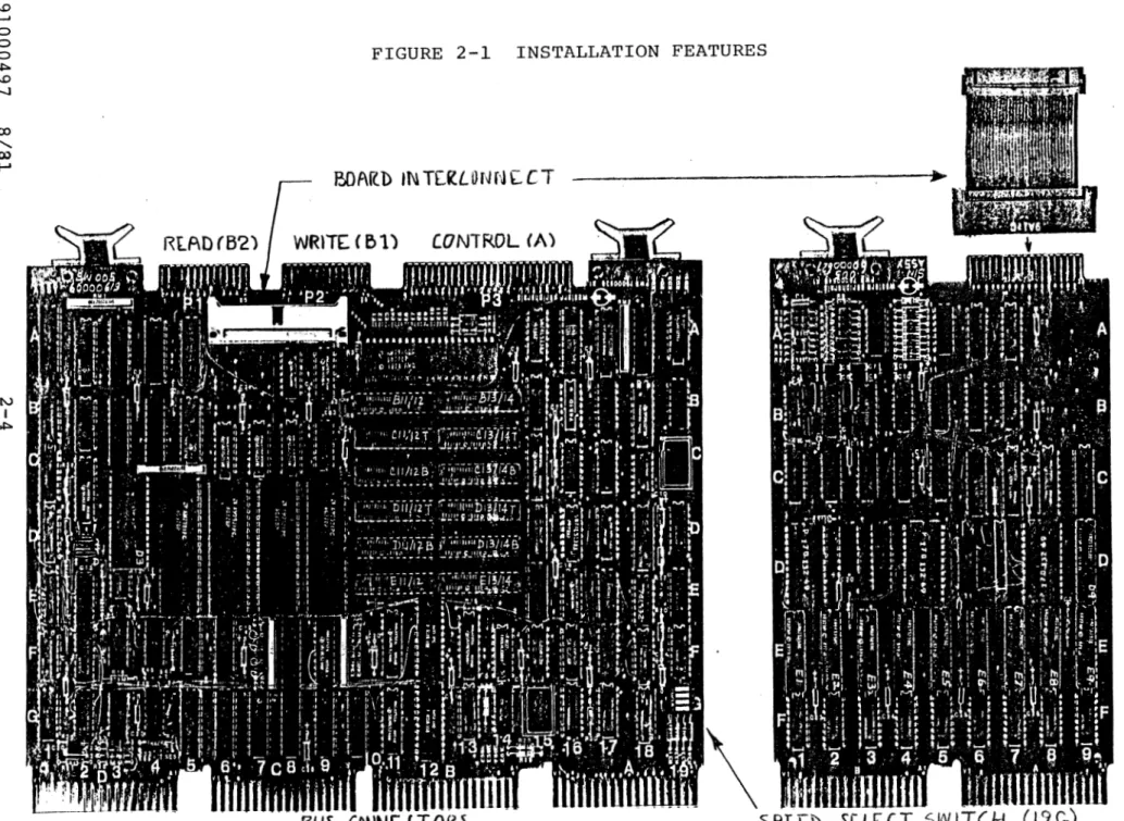
FIGURE 2-1 INSTALLATION FEATURES
BOArlD IN TEl'lLONN[CT ~~~~~~~~~~~~~~~~~~~~~~~~~ 7 "
~\
f3US CONNE.L T
Of<~SPLE.b
SCLCCT
SW ITCH
•
..
H
z
(/)
t-3 ~ t:-1 t:-1 ~ t-3
H
0
INSTALLATION
2.8 TAPE SPEED SELECTION. Tape drive speed is selected on the
controller by the setting of four switches located by the setting
of four switches located in a switch pack at location 19G. Speed
selection provides two tape speeds for both the NRZI and PE modes.
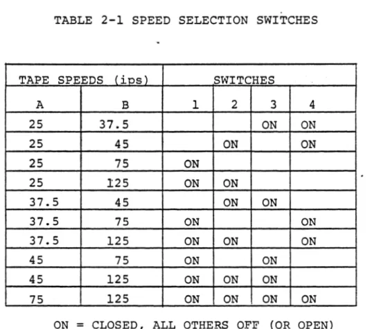
Table 2-1 provides the required speed settings for various
combi-nations, (If only one speed is used, i t may be selected on either
speed A or speed B.)
TABLE 2-1 SPEED SELECTION SWITCHES
TAPE SPEEDS (ios) SWITCHES
A B 1 2 3 4
25 37.5 ON ON
25 45 ON ON
25 75 ON
25 125 ON ON
37.5 45 ON ON
37.5 75 ON ON
37.5 125 ON ON ON
45 75 ON ON
45 125 ON ON ON
75 125 ON ON ON ON
ON
=
CLOSED, ALL OTHERS OFF (OR OPEN)INSTALLATION
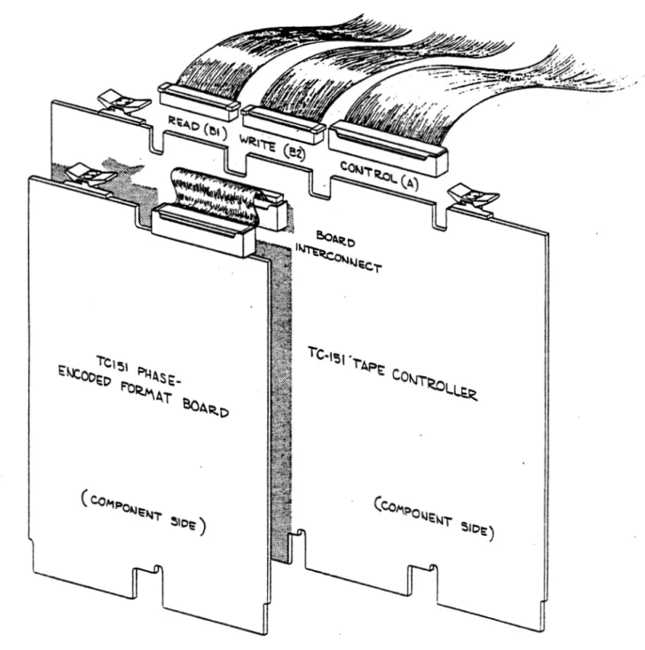
2.9
CONTROLLER BOARD INSTALLATION.
Referring to Figure 2-2,
place the controller boards into any convenient location of the
system unit.
Ensure the boards are oriented correctly (notches
on the board connectors must fit the ridges of the system unit) ,
and are seated fully.
FIGURE 2-2 INSTALLATION - CONTROLLER AND CABLES
INSTALLATION
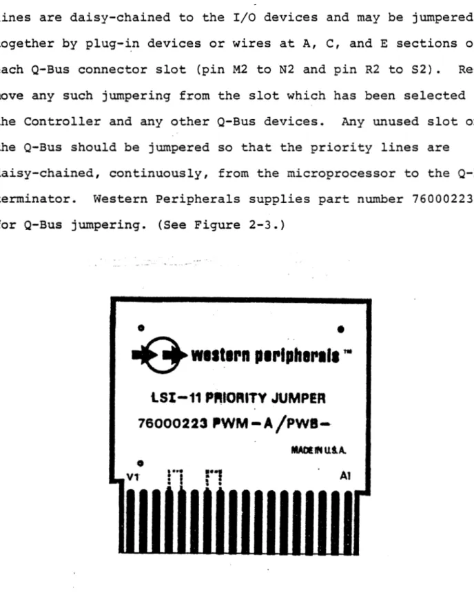
2.10 PRIORITY JUMPERS. The OMA Grant and Interrupt Acknowledge
lines are daisy-chained to the I/O devices and may be jumpered
together by plug-~n devices or wires at A, C, and
E
sections ofeach Q-Bus connector slot (pin M2 to N2 and pin R2 to S2).
Re-move any such jumpering from the slot which has been selected for
the Controller and any other Q-Bus devices. Any unused slot on
the Q-Bus should be jumpered so that the priority lines are
daisy-chained, continuously, from the microprocessor to the Q-Bus
terminator. Western Peripherals supplies part number 76000223
for Q-Bus jumpering. (See Figure 2-3.)
91000497 8/81
•
•
~
w11t1rn p1rtoh1l'lt1"'
lSI-11
PfHORITY
JUMPER
76000223
ll'WM-A/Pwa-MADllNUtA.
•
11 V1 Al
Figure 2-3 Bus Priority Jumper
2-7
INSTALLATION
2.11 COHT.ltOLLElt CABLE CONNECTIONS. Locate the following cables:
Controller-End
Description Conductors Marking
Tape Read Cable 26 Top B2
Tape Write Cable 26 Top Bl
Tape Control Cable 50 Top A
The ribbon cables are keyed to prevent incorrect connections. Check the
ribbon cable connectors to assure that all keys are in place.
2.12 Install the Read, Write, and Control cables (in that order) onto the
controller connectors as shown in Figure 2-2.
the solder side of the boards.
2.13 TAPE DRIVE INSTALLATION
The cables will exit toward
2.14 ADAPT!B. PADDLEBOAB.D SETUP. Locate a set of three Adapter Paddleboards
for each tape drive. The Adapter Paddleboards for each drive require proper
setup before installation. Setup includes proper termination, switch
set-tings, and installation of drive selection jumper plugs.
2.15 TUHillATOll.S. Consulting the tape manuals for details, remove all
termination devices from each drive. Remove the terminators from the Write
and Control Adapter Paddle boards, except the Adapter Paddle boards on the
drive located farthest from the controller. See Figure 2-5. Ensure that the
last Adapter Paddleboards have the terminators installed as shown.
2.16 COHFIGUJlATIOB SWITCHES. Set the switch module on each Control
Paddle-board according to the configuration requirements of the tape drive. Switch
settings are given in Table 2-3.
_.
l.O I-' 0 0 0""'
l.O -....) ~-00 I-' N I l.O I; '1$ ii>
•
•
•
•
•
CA Ul.l~S icllOl\l CONTllOU.EU ( 011 I'll t: VIUU8 Dll IVt: ) CAUi.ES TO NEXT IHllVE
CONTHOI,
~--- :'i--- J
, ---~lllVI~- COIH'llOI~
I
DlllVE SEJ.ECT JUMl'Ell - !!~fil!:,
J,1
----.~.vE ~~'~!~~,!~. ~-~-~-~L_,
-· .. ---· ..
. -TCTJ.1
_Q) ·'wrrcn
~
_ .. _ Trn·rti::L-cottnm111AT1ou s (o- TUJJ L ·,: .. o-u111va:: • 1 • ·-=' ....::c.
· ....
"'~"·
'·'"',,,.'" "" F.
,.,., .
"
['I
II
o"lllf o
:,;~-1~1uc-r1ous
>11·:_~_
;
:
l:;,i1·
1~·1
c·1 []
['J
I l _
;:1111~
. " -
!!.!'~1oyi;,
.WllEN Cl\fll.l::U TO l\tlOTIJl>;U DlllVE -- --
a---(SEE U-fSTAU.ATION INSTllllCTIOHS)
:~:
-
-
__J~
'l"EllMIHAlOll . .llOTlll-~11
llltlVE,_,,. CAUi.Eil 10 A
:·:
~.,
- - . - - Wll<N.
IL_~-~T;,,: ~
__:::__]J
-·...
I_
TOP A ]-c ---
- -.
CONTIU
--- -- -·· i
>I.wurrg
~
----~~~!~~·~--~~l~V~:::J
[c:
1'01• DI ---zI
- - - --·---1--
~
I
_
Jll;,~;~v-~ -'~~~;.;.~m
__
fll ___ -..
~,'.· .''.~-
__
Ill
/ /
~
I,.,
II""
::jf'----
J
I1'10:.!-. - . (TO OltlVE. J - -TEllMIHATOll •• -
!!.!fl\IO~_!:!..
I
-, I T n .... flTi
fnc1Ti·-r--1···f·
~ WllEN CAUi.ED TO ANOTllEll 1.>lllVE- LU
u
~ U.UJ ! LtU~tL.~ Lltlo:A I>
~--- ---[,;~~~-~~~~]
(
r~---ro-.,--n-2--J---HEAD
---.
{
Jll
•~~~-;~;~-~.;·m
___
.11r-~-~·: _"~---11L
r
PIOl , TO lllllVE ••b-,,
u 11 nnnrJ
1Tn •,-.-.{-~
.1.f U.I
f
U I U.l. U.U.U_U_?.
• CAUTION: UlllVE COllNECTOllS
AUE NOT KEYEU. i:llSllllE
l'llOl'Ell cmun;cT1ot1.
•• llEMOVE 'l't:lll\llHATOll~ FllOM EACll lllllVE
Figure 2-5. Details of Adopter lnstnllnllon
INSTALLATION
SWITCH SETTING
NUMBER
"ON" for normal operation
-1 "OFF for H.P. drives and for some Pertee
models
2 OFF
3 OFF
ON - For HIGH SPEED- drive
4 (Controller speed B}
OFF - For LOW SPEED drive I
;
(Controller speed A}
I
I
5 ON
I
"ON" for 9-track NRZI-only drives
l
6 I i
II OFF" for all other drives
"ON" for either dual density or PE drives
7 made by Kennedy, Digidata, or Qantex
"OFF" for all other drives
8 "OFF"
Reference Schematic Number 122036
Table 2-3 Configuration Switches
INSTALLATION
2.17 DllVB SBLICT JlJllPBIS. Ensure that the correct Drive Select Jumper is
installed in the Control Paddleboards. The last drive does not require a
Drive Select Jumper (leaving one installed will have no effect).
1. For tape drives without front panel unit select switches, use
jumper part number 122012 as shown in Figure 2-6.
2. For tape drives with front panel unit select switches:
a. Use jumper part number 122010 as shown in Figure 2-6.
b. On drives with Unit Select Switches that receive the select
lines from JlOl, ensure Control Paddleboard Jumpers are
installed from P to R (factory etch), N to M, E to F, and G
to B. See Table
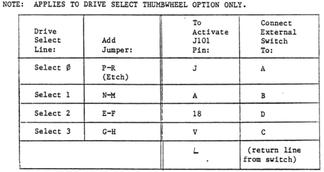
c. On drives with externally connected Unit Select Switches, connect
as shown in Table
2 .18 TAPE DllVB IJITEaCOBl1ECTIO•S. Locate a set of three ribbon cables for
each drive (one set is connected to the controller). Check that each
connec-tor has its key in place and connect the cables as shown in Table 2-5 and
Figures 2-7 and 2-8.
1
1-
--1
11
1 1
l
~---!);
;.---ij
I
INSTALLATION
NON-SELECT JD:',I?E!{ (PN 122012)
For daisy-chained erives
Without· front 9a.n.el Unit Select switches.
U"NIT SELECT JU?YIPER (P.N 122010)
For daisy-chained drives
with Unit .Select switch
(Except fourth tape unit)
UNIT SELECT JUMPER (PN 122011)
For daisy-chained drives
with unit select switches
(Install in fourth tape unit)
NOTE: No jumper plug. is required on the last tape unit or for sir1gle drive installations.
However, it should remain in the board :Or future e:Qansion of the system.
Figure 2-B Drive Select Jumoers
INSTALLATION
NOTE: APPLIES TO DRIVE SELECT THUMBWHEEL OPTION ONLY.
I
To ConnectDrive Activate External
Select Add JlOl Switch
Line: Jumper: Pin: To:
Select
'1
P-R J A(Etch) I
Select 1 N-M 11 A B
i
I
Select 2 E-F I i 18 D
I
Select 3 G-H I
v
c
I
I
'
L (return line
.
from switch)\
Table 2-4 Control Adapter Select Options
(Sequence is repeated for each drive)
Cables Paddle boards Cables
Controller Controller Drive Controller Daisy Chain Controller Drive
Board End End End End End End
Board 2 Top A Drive Drive Top A Top A Drive
Control Control Control
Board 3 Top Bl Drive Drive Top Bl Top Bl Drive
Write Write Write
Board 4 Top B2 Drive Drive Top B2 Top B2 Drive
Read Read
Table 2-5 Connector Legends and Cable Connections
INSTALLATION
2.19 Connect the Control, Write and Read Adapter Paddleboard connectors to
JlOl, Jl02, and J013, respectively, on the tape transport. (Reference the
tape drive manual for details.) Connect the paddle boards to the drive with
care. The green connectors are not keyed to the drive connectors.
There-fore, it is possible to (l) install the connector backwards or (2) to place
the Adapter Paddleboard on the wrong drive connector (e.g., Read and Write
Connectors reversed.) Avoid incorrect connection by (1) verifying the
func-tion of each drive connector and (2) physically checking the pin orientafunc-tion
of the mating connectors. If possible, secure the paddleboard connectors to
the drive connectors with screws. Neatly dress and tie all cables so the
installation appears neat and professional.
TAPE CONTROLLER
I
INST ALLA TIO N
TER1YIL.'iATORS ---~
0
>
(.)
I
I !,I
'
J
~ ~
c...
·o
-.
"O=
:::
r::;,-I ( ,
I
~
...,
<
0~ "e
=1
t::i~
I I ,
J
-g -::: ~ u I I ...J 0 -~z
0 (.) ~>
--
-
QI r.-::l
( ?A3T OF DRI'TZ i5)
CONTROL
CONTROL
? -~-DD LE::SOA ... ':\D
( PA ... '!:l.T OF DRrv-::: ~)
w"RITE
t:
'W'.RITE
:::::: P .'-\DDL.E:SOA.RD
:::
( P.<L'qT OF DRI'v-:S ~)
READ
o
3EA..D<
C::l P A.DDLE:SO.A...":\D
c:: ~
:::
c:: rO5
Figure 2-7. Single Tape Drive Connections
~
-0
:....
<
z
91000497
:.. ;.,. '
- .:: I
-: I
\ \ ~ , -! ~---: I ....
"' ' }
i
~
'-711
i- i I
:..
~ ~i
;... ~!
i
T
'"!O<t:..'io~ z..ui::a
---....;
~~
:-:.: ~;: ~: TOP.~ :::,,,.....
___ __
I-
!1
! !1
'"' ~
'T'
I 1- - - - -:'0P .~
1
""
I ~"':O~ i'r
TOP.-\.l
'
r - '
"!01:U..'t00! ,., :w ::.
-:.. c ~...
:.l ::. :.. 0 ;-;: :.l::
a
"'
0...
~ ::.' I
'
,...__,
II I
-
I :~I ~ : _ _ , )
;..-1 :.:.:
: ;.i
§! I ~
I ,...; ~ i l==~ Z.l.:~c:
-
-'~ :-:rv:~: ! • _____ _.
i
i :'OP 31
I I
T
?1 J
I
;I
I
;;,. ' I
- ; I
.:: = -<
~
g
...
·::.:~
---
;::
1 1 ~---M
-I I ,-:z.:...~ :::..-ueic:
-
i' '
I '
.... Z':rr.l ~
f
TOP 31I
T
J-1
~~
I
~I
I
=~
II
I~~
\
~
~
r
1
J.. . · -...
~--~-~ I
T
I TOP St ... ,.~Ti
-
I
a
:.:ii l < 'It•, ~§
I
~
-·
:::.:.""= ~I' ;;:-::: I
I' "":: 1·
::
n
1l
INST ALLA TIO N
-
:
-,
- < '.
:... :..: !
-
: ,~ I
..: :...L..l
::. I
"°'---! .,.. :.l >
=
:.. ~ ~::
T
I -!l ·
i 'Figure 2-8. Tape Drive Daisy-Chain Connections
SECTION III
PARA-GRAPH
3.1
3.3
3.5
3.6
3.7
3.8
3.9
3.10
3.11
3.14
3.15
3.16
3.17
TABLE OF CONTENTS
GENERAL
PROGRAMMED OPERATIONS
Operation As A Slave Device
Operation As A Master Device
CONTROLLER REGISTERS
Register Addressing
Status Register (MTS)
Command Register (HTC)
Byte/Record Count Register (MTBRC)
Current Memory Address Register (MTCMA)
Data Buffer (MTD)
TU-10 Read Lines (MTRD)
PROGRAM FLOWCHARTS
PAGE
3-1
3-1
3-1
3-2
3-2
3-2
3-2
3-6
3-11
3-12
3-12
3-12
3.1 GENERAL
SECTION III
PROGRAMMING
PROGRAMMING
3 .2 This section contains machine-level programming reference information
which describes the registers of the controller. Also contained in this
section is information on the operation of the controller, addressing, data
transfers, and interrupts. This information will be useful in understanding
the operating systems as well as the diagnostic programs. A working
know-ledge of machine-level programming, along with reference to the information
contained in this section, will allow the Customer Engineer to create small
diagnostic programs for testing specific functions of the controller.
3.3 PROGRAMMED OPEB.ATIONS
3 .4 The DEC LSI-11 · computer controls devices differently than most other
computer systems. Since registers in peripheral devices are assigned
addres-ses on the bus similar to memory, all instructions that address memory
loca-tions are, in effect, I/O instrucloca-tions. Registers in devices can take
advan-tage of all the arithmetic power of the processor. There is no limit to the
number of registers that a device may have, providing great flexibility in
the design and control of peripheral equipment.
3.5 OPERAl'ION AS A SLAVE DEVICE. All command and status information is
transferred with the CPU acting as the master device and the controller
acting as the slave. The individual bits within the Command Register control
the operations of the device. For example, the command to make the tape
system read a block from tape is provided by properly setting bits 1 through
3 in the C01DI11and Register. Status conditions are also handled by the
PROGRAMMING
ment of bits within the registers. All command and status information is
written or read by program instructions. Indications of operation complete
can be through examination of "the status and command registers or by
utili-zing the system interrupts.
3 .6 OP:Elil'ION AS A MASTER DEVICE. .m.ce a function command has bee·n issued
to the controller, the operation is executed by the controller, utilizing DMA
bus transfers to move the data to or from the memory. The Byte/Record
Coun-ter RegisCoun-ter and the Current Memory Address RegisCoun-ter are updated throughout
the DMA activity. At the conclusion of an operation, completion is indicated
to the CPU through the status bits and also an interrupt (if enabled)•
standard interrupt vector (224 octal) is used.
3.7
CORT.ROLLER UGISTERS •"
The
3.8
REGISTER ADDBESSIHG. The registers of the tape controller occupy busaddress locations 772 520 through 772 532 and are addressed by the CPU with
the controller being the slave device. These addresses are placed on the bus
in the same way that memory is addressed. The controller latches the address
until the completion of the transfer.
3.9 S'.rATIJS REGISTER (MTS) 772 520. The status register contains only read
bits, providing the CPU with status indications from both the tape drive and
the controller.
91000497 8/81 3-2
PROGRAMMING
REGISTER BIT ASSIGNMENTS:
ND
II.LEGAL COM?W
END OF FI!.E PARITY ERROR
BUS·GRANT LA
E?ID OF ?APE
RECORD LENGTH
BAD !A.PE ERR
NON-EXISTENT
SELECT REMOTE
TE
ERROR
OR.
MEMORY
I
15 14 13
I - I
l
I
12 111 10
I
I
tI
9 8 7 6
I
5l
I
l
1'
I
:I
iI I
I
I
I l
i
i
BEGINNING OF TAPE ---~
7 CH.A.i.'l'NEL
4 3
I
I
l
I
I
II
II
1
l
I
!
.
'
TAPE SLOW!NG DOWN - - - '
WRITE LOCK REWIND STATUS
2
l
I
i
I
,
0..
I
II
l
I II
I ITAPE UNIT READY ---~
l. MTS BIT 15 ILLEGAL COMMAND (ILL COM) - When an illegal command is
received, the CU RDY bit remains true, and the command is
dis:;e-garded. The Illegal Command bit is set for any of the following
conditions and sets the ER.It bit in the Command Register:
a. AJJ.y tape command initiated during a tape operation (CU RDY
bit is false)
b. AJJ.y tape command where the selected drive is not on-line
(Select Remote bit is false).
c. Any write command on a drive which is file protected.
d. The drives Ready status line going false during an operation.
2. MTS BIT 14 END OF FILE (EOF) - The EOF bit is set when a file mark
character is :ietected during a Read, Space Forward or Space
R.e-verse operation. The EOF bit sets the ERR bit in the Command
Register.
3. MTS BIT 13 ODD LENGTH RECORD (OLR) - The OLR status indicates that
part of the final word t:'ansferred to memory contains
insignifi-91000497 8/81 3-3
PROGRAMMING
cant zeros filled by the controller after reading a record which
did not fill the final word in the data register.
4. MTS BIT 12 PARITY ERROR (PAE) - The Parity Error bit is set when
the controller detects a parity error, I.RC error, or Postamble
error during a Read, Write, or write with Extended Record Gap
operation. The PAE bit does not affect the transfer of data.
During a Write operation, the entire record will be transferred
onto tape or in a Read operation, the entire record will be
trans-ferred to memory. The PAE error bit will set the ERR bit in the
Command Register.
5. MTS BIT 11 BUS GRANT LATE (BGL) - The Bus Grant Late bit is set when the controller overflows (or· empties) its internal buffer and
information is lost during an operation. This condition causes an
immediate termination of the Read or Write operation in progress.
This bit will also be set during a Read operation when the
in-ternal buffer of the controller is not emptied before the tape
begins to stop. The ERR bit in the Command Register will be set
when the BGL bit is true.
6.
7.
MTS BIT 10 END OF TAPE (EOT) - The End of Tape bit is set when the
EOT marker is encountered while the tape is moving in the forward
direction. The bit will be reset when the EQT marker is passed
while performing a Rewind or Space Reverse operation. The ERR bit
in the Command register will be set when the EOT bit is true.
MTS BIT 9 RECORD LENGTH ERROR (RLE) - The Record Length Error bit
will be set during a Read operation when the length of the record
being read exceeds the memory allocation as indicated by the
Byte/Record Counter. When the Byte/Record Counter indicates the
PROGRAMMING
end of the memory allocation, data t:'ansfer will stop and the
controller will continue to advance the tape to the next
inter-record gap. A Record Length Error stops the incrementing of the
Byte/Record Counter and the Current Memory Address Register and
sets the ERR bit in the Command Register.
8. MTS BIT 8 BAD TAPE ERROR (BTE) - The Bad Tape Error bit sets when
a character is detected (read strobe) during the gap shut-down (or
the slowing down) for aJ.l operations (except rewind). When a Bad
Tape Error is detected, the ERR bit in the Command Register is
set.
9 • MTS BIT 7 NONEXISTENT MEMORY NXM) - The Nonexistent Memory bit is
set during direct memory operations (when the controller is bus
master and is performing data transfers with the bus) and the
,
controller does not receive a Slave Sync response within 14
micro-seconds after it issues the Master Sync signal. When the
Non-existent Memory error bus time-out is detected, the Read or Write
operation is terminated, stopping the tape in the interrecord gap,
and setting the ERR bit.in the Command Register.
10. MTS BIT 6 SELECT REMOTE (SELR) - The Select Remote bit is set when
the addressed tape drive is on line and cleared when the addressed
tape unit is off line, powered off, or disconnected.
11. MTS BIT 5 BEGINNING OF TAPE (BOT) - The Beginning of Tape bit is
set when the tape drive detects the Load Point mark at the
begin-ning of the magnetic tape.
12. MTS BIT 4 7 CHANNEL (7 CH) - The seven channel bit is not used.
PROGRAMMING
13. MTS BIT 3 SLOWING DOWN (SDWN) - The Tape Slowing Down (or Settle
Down) bit is set whenever the tape unit is stopping after a
rewind-ing operation.
14. MTS BIT 2 wRITE LOCK (WR.I.) - The Write Lock bit is set to prevent
the software from attempting to write information on the tape when
the operator has removed the write-enable ring from the supply
reel on the tape drive.
15. MTS BIT l REWIND STATUS (RWS) - The Rewind Status bit is set by
the selected drive when it receives a Rewind comna.nd from the
controller or operator panel and is cleared by the selected drive
when the tape arrives at BOT, completing the Rewind operation.
16. MTS BIT
0
TAPE UNIT READY (TUR) - The Tape Unit Ready bit is setwhen the selected tape unit is stopped and is cleared when tqe
controller begins to execute a function command.
3.10 COMMANI> REGISTER (MTC) 772 522. This register receives operational
commands from the CPU and provides status information from the
con-troller and the tape drive.
COMMAND REGISTER BIT ASSIGNMENTS:
15 14 13 12 11 10 9 8 7 6 5 4 3 2 l 0
Binary bit weights:
ERROR---DENSITY/PACKING MODE
POWER CLEAR ~---'
LATERAL PAltITY - - - '
DRIVE SELECT CONTROLLER READY INTERRUPT ENABLE
4 2 l
EXTENDED ADDRESS - - - _ . _ _ ,
FUNCTION---...J..--i""--J
GO
---l
PROGRA.J."1MING
1. MTC BIT 15 ERROR (ERR) - Set as a function of bits 7-15
of the Status Register (MTS) being set. This bit is
cleared as the result of an Initialize or a Go command
to the tape unit.
2. MTC BITS 14, 13 (DEN 8, DEN 5) N - These density select
bits are not used by the controller. Density is
con-trolled by the tape drive or
by
bit 10 of this register.3. MTC BIT 12 POWER CLEAR (PCLR) - This bit provides the
means for the processor to clear the controller and the
tape drives without clearing other devices in the
system. The PCLR bit is always read back by the
pro-cessor as zero.
4. MTC BIT 11 LATERAL PARITY (PE'VN) - This bit is
appli-cable only to 7-track operations, and is ignored by
the controller.
5. MTC BITS 10-8 DRIVE SELECT (SLT
1,
2, 4) - These bitsspecify one of the eight possible tape units. All
operations defined in the MTC register and all status
conditions defined in the MTS register refer to the
unit indicated by these bits. Drive selection of the
last 4 drives may be forfeited by jumpers which use
bit 10 either to select the IBM pack mode (see MTRD
bit 10) or to select high density mode (1600 bpi PE).
PROGRA.i.'1MING
DRIVE SELECT LINES
LOGICAL DRIVE
DRIVE NO. ADDRESS SLl (Bit 8) SL2 (Bit 9) SL4 (Bit 10)*
1 Yl False False False
I
(NRZIFalse
I
mode
2 1 True False or
Falser
DEC3 2 False True packing)
4 3 True True False
I
5/1* 4/0* False False True (PE
mode
6/2* 5/1* True False True or
IBM
7/3* 6/2* False True True packing)
8/4* 7/3* True True True
*BIT 10 MAY BE JUMPERED TO SELECT PE MODE OR IBM PACKING.
6. MTC BIT 7 CONTROLLER READY (CUR) - This bit is cleared at the
start of a tape operation and is set at the end of a tape
operation to indicate that the controller is ready to accept a new
command.
7. MTC BIT 6 INTERRUPT ENABLE (INT ENB) - When this bit is set, an
interrupt occurs whenever either the Controller Ready bit or the
ERR bit goes true or whenever a rewinding tape unit arrives at
BOT. In addition, an interrupt occurs for an instruction that sets
the INT ENB bit but does not set the GO bit.
8. MTC BITS 5, 4 EXTENDED BYTE ADDRESS (YBA 17, XEA 16) - These bits
access the two most significant bits of Current Hemory Address
Register, providing an 18-bit memory addressing capability.
PROGRAMMING
9. MTC BITS 3 - l FUNCTION BITS - These bits select one of eight
command functions.
a.
Bit 3 Bit 2 Bit l
0 0 0 Off Line
0 0 l Read
0 l 0 Write
0 l l Write EOF
l 0 0 Space Forward
l 0 l Space Reverse
l l 0
Write/E.R.G.
l l l Rewind
Off Line Command. This command, which places the
select-ed drive off-line, is usually precselect-edselect-ed by a rewind command
after cotllpleting all operations on the reel of ~ape. The
controller does not go Busy, leaving it free for use with
other drives in the system.
b. Read Command. The program must specify a byte count (in twos
complement - or negative - form) and an initial address. The
controller reads a single record from tape and sends the data
via DMA operations to the locations specified by the Address
Register until the EOR gap is encountered or the Byte Counter
overflows, whichever occurs first. For operations with
vari-able length records, a large byte count ensures that the
entire record will be read. The length of the record of
unknown size can then be determined after it is read by
comparing the Byte Counter at the end of the operation to its
initial setting. The setting of BGL status during the record
indicates that information has been lost, but data transfers
PROGRAMMING
continue until the byte counter overflows or the EOR gap is
detected.
c. Write Command. The program must specify a (negative) byte
count. and an initial bus address. If Write Lock. is true, GO
sets Illegal Command, and the controller rejects the
operation. Otherwise, the Controller makes an immediate data
request for the first word, and writes the data it receives
from the locations specified by the address counter onto the
magnetic tape until either the byte counter overflows or a
BGL or NXM error occurs, at which time the controller
terminates the record.
d. Write End of File Command. Unless Write Lock is set, GO
starts the controller into operation to write a file mark.
With Write Lock true, the command is rejected.
e. Space Forward Command. The program must specify a (negative)
byte count equal to the number of records to be spaced. The
controller spaces forward over the given number of records
unless it encounters a file mark or the end of tape. To
space over a file, the program can simply give a zero
(maximum) byte count.
f. Space Reverse Command. The program must specify a (negative)
byte count equal to the number of records to be spaced. If
BOT is true, GO sets the Illegal Status bit, and the
controller does not go into operation. Otherwise, the
controller spaces reverse over the given number of records,
but it stops the tape automatically upon encountering a file
mark or the Load Point. To space over a file, the program
can simply specify a zero (maximum) byte count.
..
g.
PROGRAMMING
Write with Extended Record Gap Command. The operation of
this command results in a three and one-half inch length of
tape being era~ed before the data is written. This provides
a method of erasing a bad record from a damaged portion of
tape before rewriting the data farther down on the tape. A
Space Reverse One Record operation generally precedes this
command.
h. Rewind Command. This command initiates a rewind operation in
the addressed tape drive, which rewinds the tape onto the
supply reel at high speed, and stops at BOT. The controller
does not go Busy, leaving it free for further use by the
program during the rewind operation.
3.11 BY'?E/XECOBD COUNT B.EGISTD. (MTJmC) 772 524. The MTBRC is a 16-bit
•
binary counter which is used to count bytes of memory during Read or Write
operations, or to count records in a Space Forward or Space Reverse
opera-tion. When used in a Write or Write with Extended Record Gap operation, the
MTBRC is initially set by the program to the 2's compliment of the number of
bytes to be transferred from memory to tape. The MTBRC increments by one
immediately after each byte memory access or by two after each word transfer •
The MTBRC overflows to zero after the last byte
of the record has been read from memory. Bus transfers are terminated by
this byte count zero condition.
3.12 'When the MTBRC is used in a Read operation, it is set to the 2's
comple-ment of a number equal to or greater than the maximum expected record length,
indicating the memory allocation for the read data. A Record Length Error
(RLE) occurs when the actual record length is greater than the allocated
memory, as indicated by the MTBRC overflowing before the EOR gap is detected.
PROGRAMMING
3.13 When the MTBRC is used in a Space Forward or Space Reverse operation,
it is set to the 2 's compliment of the number of records to be spaced over·
It is incremented by one each ..time a record passes the head whether the tape
is moving in the f orw~ra or reverse direction.
3.14 cmwmT MEMOll ADDRESS REGIST.EB. (MTCMA) 772 526. The M'l'CMA _register
contains 18 memory address counter bits. It is used in DMA operations to
provide the memory address for data transfers in Read Write and Write with
Extended Record Gap operations. Prior to issuing a command, the MTCMA is set
to the memory address to be used for the first data transfer. The M'!CMA. is
incremented by one immediately after each byte transfer and by two after each
word transfer. Thus, at any instant of time, the MTCMA points to the next
6
higher address than the one which had most recently been accessed. When the
entire record has been transferred, the Ml'CMA. contains the address of the
word following the final transfer for the record. After Bus Grant Late (BGL)
and Non-Existent Memory (NXM) error conditions, the MTCMA contains the
address of the location in which the failure occurred.
3.15 DAXA BUFFEi. (M.1:'.D) 772 530. The data buffer is a register which is used
for diagnostic purposes. After the completion of an operation, the 9-bits of
the CRC or LRC are placed into the data register and ma.de available to the
program, depending upon the TU-10 Register bit 14.
3.16 TU-10 BEAD LINES (M:rBD) 772 532. In addition to its use for diagnostic
purposes, this register receives additional command bits from the CPU and
provides additional status information from the controller and from the tape
drive.
PROGRAMMING
TU-10 READ LINES REGISTER BIT ASSIGNMENTS:
15 14 13 12
u
·10 9 8 7 6 5 4 3 2 l 0I
I
1-
I I
II8M
I
IPI
116
Is
14
j 3i
2!
1I
0
I
C SELECT
I
E GENERATE
UT-DOWN .TIMERLRC/CR
BAD TAP
GAP SH CORR.EC EDIT/
TABLE PARITY ERR.OR IDEN
\
7
I.RC
0- ,
P1. MTRD BIT 15 TIMER (lOKHz) - This read-only bit provides the
diag-nostic program with the output of a 10 KHz timer. This timer bit,
having a 50% duty cycle, is used by the diagnostic program for
measuring the time duration of tape operations.
2. MTBD BIT 14 LRC/CRC SELECT (LRCS) - This write/read bit, when set,
disables the CRC word from remaining in the data register at the
conclusion of an operation, replacing it with the I.RC character.
3. MTBD BIT 13 BAD TAPE GENERATE (BTG) - If set during an operation
in progress this write-only diagnostic bit simulates a bad tape
error by prematurely setting end-of-record status.
4. MTRD BIT 12 GAP SHUT-DOWN BIT (GSB) - This bit indicates the
controller's post-record positioning time period (Main Sequence 2
or 3) to the diagnostic program.
5. MTBD BIT 11 CORRECTABLE PARITY ERROR (CPE) - This bit is true in
the Read Mode when a phase encoded tape is being corrected because
of a single channel dropout.
6. MTRD BIT 10 IBM PACK MODE - - When this Write/Read bit is set by
the CPU, the IBM Pack mode is set, enabling the controller's
internal byte swapping circuitry. IBM/industry-compatible tapes
may then be read.or written by the controller.
3.17
3.18
PROGRAMMING
7. MTRD BIT 9 EDIT MODE/P.E. IDENTIFICATION (EDIT/IDEN) - When this bit is
set by the CPU, the Edit Mode is enabled, issuing the Overwrite command
to the tape drive. When read, this bit is true to indicate the
Identi-fication Burst of a phase encoded tape is being read by the controller.
8. MTRD BITS 0-8 LONGITUDINAL REDUNDANCY CHARAC'rER (LRC
0-7,P) -
One ormore of these bits will remain set to indicate incorrect longitudinal
parity was read by the respective channel. (NRZI Mode)
PROGRAM FLOWCHARTS
The following pages contain flowcharts which illustrate the program
flow required to handle controller operations, including Write,
Write End of File, Read, Space Forward and Reverse, and Rewind
opera-tions. These illustrations generalize some of the specific details
of controller programming, but do identify overall program
require-ments for each operation.
CL£AR WRITE
RETRY COUNTER
SELECT
UNIT/
CHECK STATUS
SEND INITIAL ADDRESS, BYTE COUNT
CMD WRITE,
UNIT/
PARITY, GO
91000497 8/81
IF RETRY,
Cl1D IS: WERG
YES
(OR INTERRUPT)
INCREMENT
RETRY
' COUNTER
SPACE REVERSE
ERASE
Figure 3-1. "WRITF' Flow Chart
3-14
91000497
C.MO WRIT!
EOF, EVEN
i'ARITY, Ullli
' GO
NO
~10
110· .
8
St:L.!Ci UNI i/ ':HEC:< Si,l.T'JS
..
Y
i:--~
{OR I Nn?.RUP'i)
NO
PROGRA:tIMING
CMO WRIT!
EOF, 000
?ARITY, UHIT
' GO
Figu:-e 3-2. ~¥RITE E...'i"D OF F!LE" Flow Chart
"'
.l
i
'.'lO
..
.110 .
NO
9100049_7. 3/81
8
ICl.EAR
i\EAO
i\Ei'i'l.Y
COUNT!R
s;:t.~CT
UN Ii/ CHECK Si~TIJS
ISSUE INITIAi. ADDRESS, 6Yi£
COUNT
CMO READ,
UNIT,
PARITY, GO
(CR
I
HT'ERRUP'!') I
I
.,~-. -~·" I
I ,lfCREl'1£NT
i\ETIY
COIJN'i!R
S?~C! i\E'IERS~
'.'lC
Figure 3-3. "'?..!AD" Flow Char-=
3-16
0
~;( 1 'T'.A
I
I
~jQ
NO
"·
!I
91000497 8/81
8
·'
S~!.:'.CT
UNIT/ CHECK STATUS
ISSUE RECORD COUNT
ISSUE S?AC~
C:MMANC,
UNIT, 1~0
I
e
3
-i.,
-·
NO
•
...
NO
91000497 8/81
8
I
Yi:-· . ; )
S£1.£CT
UNIT/
CMECK STATUS
YES
ISSUE COl'll".ANO,
UNIT & GO
I
8
3-18
PROGRAMMING
•
SECTION IV
·•
"
PARA-GRAPH
4.1
4.3
4.5
4.9
4.10
4.11
4.13
4.14
4.15
4.16
4.17
4.18
TABLE OF CONTENTS
PAGE
TAPE FORMAT 4-1
Nine-Track NRZI Format 4-1
Nine-Track PE Format 4-3
Missing Characters 4-5
End-Of-File Mark 4-5
Tape-End Markers 4-6
Record Length 4-6
Effective Transfer Rate 4-6
TAPE DRIVE INTERFACE 4-7
Interface Signals 4-7
Interconnections 4-7
4.1 TAPE FORMAT
SECTION IV
TAPE INTERFACE
4.2 The Western Peripherals Tape Controller interfaces to industry-standard
tape drives which write nine or seven bit characters laterally across the
tape. The density of the characters written on the tape is determined by the
type of tape drive, the density selection made on the tape drive, and (in
some cases) the density selection made in the command issued by the CPU. A
data block (record) written on tape consists of data characters and error
checking characters (or a preamble and postamble). Every data character
consists of the data byte plus a parity bit that is generated by the
control-ler to conform with odd or even parity as specified by the program or the
format. A record (or block) of data on tape represents the data transferred
to or from a block of memory in one Read or Write operation. The controller
separates adjacent records by automatically erasing a 0.6 inch (0.75 inch in
7-track) segment of tape to form an interrecord gap (IRG) between them. The
controller always stops and starts the magnetic tape in an interrecord gap.
4.3 NINE-TR.ACK NJlZI FORMAT. As shown in Figure 4-1, each data character
contains eight data bits and one odd vertical parity bit. Following the last
data character, the End of Record gap (three blank characters) is written,
followed by a Cyclic Redundancy Check (CRC) character, followed by three more
blank characters, concluded by a Longitudinal Redundancy Check (LRC)
charac-ter• Following the LRC character, a 0. 6 inch IRG is written, in which all
nine tracks are erased. The LRC character produces an even longitudinal
parity in each of the tracks along the length of the tape. Reading or
•
~ I-' 0 0 0 ~ \.0 -...) CX> ... CX> I-' ~ I N,.
TRACK CHANNEL--.
(1
4 9 6 8 0 7 6 2 6
p 4 3 3
\ \
r----,
7 2, nn·r TAn
6 1
•
•
4•
-c-- FOHWAllD TAPE MOTION
I I
•
•
~8
u 11< u"
DOT GAP ~ DATA 3 BLANK 3 DI.ANK INTF.fl-flECOllD OAP NEXT
12 CllAllACTEn MINIMUM CllAHACTF.ns CllAllACl'f:ns o. 6 INCH NOMINAL ...j...-- irnconn
HEFEHENCE
EOOF:
film§
3. 6 INCHES NOMINAL
1. TAPE SHOWN WITH OXIDE SIDE UP.
2. CHAN»ELS 0 THROUGH 1 CONTAIN DATA BITS IN DESCENDl:NG ORDER or SIGNlflCANCE. 3. CHANNEL P (PARITY) ALWAYS CONTAINS ODD DATA PARITY.
4. EACH BIT OF THE LllC IS SUCH THAT THE TOTAL NUMBER or"!" BITS IN THAT TRACK {INCLUDING THE CRC AND nu: lJlC) IS EVEN. IN THE 9-TRACK FORMAT THE LRC WILL NEVER BE AN ALL-ZEROS CHARACTER.
enc I.TIC ( ~.G INCll NOMINAL
fllR FILE MARK OAP I FMK
5. IT IS POSSIBLE FOR TllIS CRC CHARACTER TO BE ALL ZEROS, IN WHICH CASE A REAO DATA STROBE WILL NOT BE GENERATED.
6. A FILE MARK IS A SINGLE CHARACTER RECORD HAVING "I" BITS IJll CHANNELS 3, 6, AND 1 FOR BOTH THE DATA Cll .. RACTER AND TIIE LllC. THE enc CONTAINS ALL ZEROS. Tmi; RECORD IS SEPARATED BY 3. 5 INCHES FROM THE rREVlOllS RECORD AND BY A NORMAL DIG {O. 6 INCH) FROM THE FOLLOWING RECORD.
7, DATA PACKING DENSrrY IS FIXED AT 800 BITS PER INCH.
Figure 4-1 9-Track NRZI Tape Format
TAPE.INTERFACE
ing, the controller checks to ascertain that the lateral parity of every data
character is odd and that every track has even longitudinal parity.
4.4 The 9-track file mark consists of a single character record with a
one-bit in channels 3, 6, and 7; the remaining channels contain zeros. The
CRC character is left blank, but an LRC character is written which is
iden-tical to the file mark character.
4.5 NINE-TR.ACK PE FORMAT. The standard Phase Encoded (PE) 1600 bits per
inch format, shown in Figure 4-2, consists of a preamble, a variable length
data block, and a postamble. The preamble consists of 40 characters
con-taining zeros in all tracks followed by a character concon-taining ones in all
tracks· Each data character contains eight data bits and an odd vertical
parity bit. The last data character is followed by the postamble (which is
the reverse image of a preamble), an ones character followed by 40
all-zeros characters.
4 .6 When the tape is at load point (beginning of tape) and the first data
block is to be written, it is preceded by an identification burst, consisting
of alternate ones and zeros in the parity (P) track, with all other tracks
erased. The file mark consists of 40 characters of zero characters similar
to those in the preamble, except that channels l, 3, and 4 are erased.
4. 7 Phase encoded recording differs from NRZI recording in the recording
method as well as the format. In Figure 4-3 NRZI and phase encoded waveforms
of similar dens! ty are compared. The NRZI waveform shows a change in flux
polarity for each binary one bit. A binary zero is represented by the
absence of a flux change.
•
l.O I-' 0 0 0"""
l.O -....] co"
coI-'
"""
I"""
•
TRACK CHANNEL
(
m1111111111111111m )
11- - ,
I11 BOT 'rAB I
y
11
I
IL - - _JI I . I
4 9
6 8
0 7
I fl
2 5
p 4
3 3
7 2
5 J
•
•
Ii•
BLOCK (Oil HECOllO)
·-
~,---FORWARD TAPE MOTION
mmrrn 1nmrrn11I111rmr 111rnnm
nu
rm
ummn
mn
111111mm11rn
1mlll1rII1m1
tmm
1mm11mrnunnrn 111mmnn11n11
flmnfIT1mn1 £lm1m11mJJnlllmum11
nrnuurmlIIJmm1mun11rmrn11
mnmmmnmm111mrmumrmnmrnmrm
unmm1rmmrn umum
1
mJrn1m1rnu
rrnurn11rnrn
111numrm1nmmnrr1m1
IIIID
Ill
IIDI
mu
I
mm rrm
UJITIIIIIl1IDIIlllllllllHilllJJ1 IIIIIllll llIIJIJIIIIIlllilill
m
llllllwnu1Illlum1l1llllllm
111111111111wnnrnmmm1fIIlIIIIlI1IIJilIIIill11J
illiilIIIIIllIIJiflIUllllllUlllilIIUIIIDlIIIIITlllITITIJ1lTTUHIJT1II1illIJlJifj
ITITIIIIflIIlillIIllllllllllllllllilIIlIIITIIUTIJlflITTIIIIilllIIllJIIIIIIIllilllIIIIIlilllliilll
UlllllllJ
I 111111111111111111111111111111 1111111111111lllllllllllll111111111111111111111 IIlTIII illllEFERENCP,I I I t II II
I'
EDGE I I 11
1
I
O. 6 ln~m1n4 PREAMBLE11
[l' c-AI 1 4 ... . .
~
POSTAMDLE ..f•
•
•
t"'
t'I LI': MA II K.,
I
rrmmrnrnmnmmmn
11mnmmmmnnmm m
11
rm nm mm mm nm un
11
nmmnrrmnm mrnm rn
11mrnnrnnnmmnmm1
[JilllliillllIIIlllllIUllllll
I
I. 71n.(mln) ~· 31n. (min)I
40 ALL-ZERO I...
..
...
..
'""'
· \ CllAllACTERS
+
I
14
10 ALl.-7.ERO-1
4 INTF.llHECOHO GAP . . . .I
NEXT llECOllDCHAllACTEllS O.fi Inch 1 .16 FILE J\1AllK
t
- 10. 40 ALL-ZEHO CllARACTEHS
I ALL-ONES GllARACTEH TRAILING
1 ALI.-ONES CllAHACTEH
WITH CH ANNE J.S I.• 3. ANIJ 4 OEAU
END
PE IDENTIFICATION llURST. ALTEHNATE ZEHOS &