'.
ATARI" HOME COMPUTER SYSTEM
/ 'TECHNICAL
REFERENCE NOTES
includes:
Operating System User's Manual
Operating System Source Listing
and
Hardware Manual
TO All PERSONS RECEIVING THIS DOCUMENT
Reproduction is forbidden without the specific written permission of ATARI, INC. Sunnyvale, CA 94086. No right to reproduce this document,
nor the subject matter thereof, is granted unless by written agreement with, or written permission from the Corporation.
)I\.®
ATARI®
HOME COMPUTER SYSTEM
OPE RA TI NG SYSTEM
USER'S MANUAL
COPYRIGHT 1982, ATARI, INC. ALL RIGHTS RESERVED
TO All PERSONS RECEIVING THIS DOCUMENT
Reproduction is forbidden without the specific written permission of ATARI, INC. Sunnyvale, CA 94086. No right to reproduce this document, nor the subject matter thereof, is granted unless by written agreement with, or written permission from the Corporation.
Every effort has been made to ensure that this manual accurately documents this product of the ATARI Home Computer Division.
However, due to the ongoing improvement and update of the computer software and hardware, ATARI, INC. cannot guarantee the accuracy of printed material after the date of publication and disclaims
PREFACE
ATARI Home Computer
Operating System USER'S MANUAL
17
1
INTRODUCTION
18GENERAL DESCRIPTION
OF THE ATARI COMPUTER SYSTEM
18Conventions Used in This Manual
20
HEXADECIMAL NUMBERS
20
MEMORY ADDRESSES
20
KILOBYTES OF MEMORY
20
PASCAL AS AN ALGORITHM-SPECIFICATION LANGUAGE
20
MEMORY LAYOUTS
20
BACKUS-NAUR FORM (BNF)
21
2
OPERATING SYSTEM FUNCTIONAL ORGANIZATION
22Input/Output Subsystem
22Interrupt Processing
22Initialization
22Power-Up
22System Reset
23Floating Point Arithmetic Package
243
CONFIGURATIONS
25Program Environments
25Blackboard Mode
25Cartridge
26Diskette-Boot
26Cassette-Boot
26RAM Expansion
27Peripheral Devices
27Game Controllers
27Program Recorder
27Serial Bus Devices
284
SYSTEM MEMORY UTILIZATION
29RAM Region
29Page
0 30Page
1 30OS Data Base
30User Workspace
31Boot
.~egion
31Screen Display List and Data
31Free Memory Region
31Cartridges A and B Mapped 1/0
Resident OS and Floating Point Package ROM Central Data Base Description
Memory Dynamics
System Initialization Proce'ss Changing Screen Modes
5 1/0 SUBSYSTEM
Central 1/0 Utility
CIO Design Philosophy
DEVICE INDEPENDENCE DATA ACCESS METHODS
MULTIPLE DEVICEIFILE CONCURRENCY UNIFIED ERROR HANDLING
DEVICE EXPANSION
CIO CALLING MECHANISM
HANDLER ID -- ICHID [0340] DEVICE NUMBER -- ICDNO [0341] COMMAND BYTE -- ICCMD [0342J STATUS -- ICSTA [0343J
BUFFER ADDRESS
ICBAL[0344J AND ICBAH [0345] PUT ADDRESS
--ICPTL [0346] AND ICPTH [0347] BUFFER LENGTHIBYTE COUNT
--ICBLL [0348] and ICBLH [0349] AUXILIARY INFORMATION
--ICAX1 [034AJ and ICAX2 [034B] REMAINING BYTES (ICAX3-ICAX6)
31 32 32 32 32
33 33
34
36 37
37 37 38 38 38
38
39 39 40 40
40
40
40
6
CIa Functions 41
OPEN -- Assign Device/Filename to IOCB
and Ready for Access 41
CLOSE -- Terminate Access to Device/File
and Release IOCB 42
GET CHARACTERS -- Read n Characters
(Byte-Aligned Access) 43
PUT CHARACTERS -- Write n Characters
(Byte-Aligned Access) 43
GET RECORD -- Read Up To n Characters
(Record-Aligned Access) 44
PUT RECORD -- Write Up To n Characters
(Record-Aligned Access) 44
GET STATUS -- Return Device-Dependent
Status Bytes 45
SPECIAL -- Special Function 45
Device/Filename Specification 46
I/O Example 47
Device Specific Information 50
Keyboard Handler 50
CIa Function Descriptions 51
Theory of Operation 51
Dis P I a y Ha n die r ( S: ) 54
Screen Modes 54
TEXT MODE 0 54
TEXT MODES 1 AND 2 55
GRAPHICS MODES <Modes 3 Through 11) 56
SPLIT-SCREEN CONFIGURATIONS 56
cto
Function DescriptionsUser-Alterable Data Base Variables Theory of Operation
Screen Editor (E:)
CIa Function Descriptions
User-Alterable Data Base Variables
Cassette Handler (C:)
CIa Function Descriptions
Theory of Operation File Structure
57 61 62
66
67 70
72 72
P r in t e r Ha n d 1 e r ( P: )
CIa Function Descriptions Theory of Operation
Dis k F i 1 e Ma nag e r ( D: )
CIa Function Descriptions DevicelFilename Specification
Filename Wildcarding
Special CIa functions Theory of Operation
FMS Diskette Utilization
Non-CIa 110
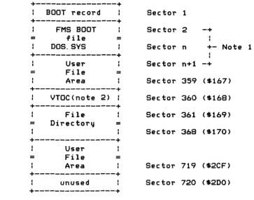
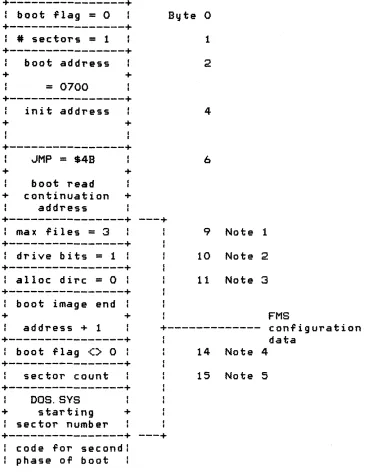
FMS BOOT RECORD FORMAT BOOT PROCESS MEMORY MAP VOLUME TABLE OF CONTENTS FILE DIRECTORY FORMAT FMS FILE SECTOR FORMAT
Resident Device Handler Vectors
Resident Diskette Handler Diskette Handler Commands
Serial Bus 1/0
6 INTERRUPT PROCESSING
76 76 78 78 79 81 82 84 87 89 90 92 93 94 95 96 96 97 99 101 102
Chip-Reset 103
Nonmaskable Interrupts 103
Stage 1 VBLANK Process 104
Stage 2 VBLANK Process 105
Maskable Interrupts 107
Interrupt Initialization 108
System Timers 109
Usage Notes 109
POKEY Interrupt Mask 110
Setting Interrupt and Timer Vectors 110
Stack Content at Interrupt Vector Points 111
Miscellaneous Considerations 112
7
SYSTEM INITIALIZATION 116Power-Up Initialization (Coldstart) Procedure 116 System Reset Initialization (Warmstart) Procedure 119
8 FLOATING POINT ARITHMETIC PACKAGE 121
9
8
Functions/Calling Sequences 122
ASCII to Floating Point Conversion (AFP) 122 Floating Point to ASCII Conversion (FASC) 122 Integer to Floating Point Conversion (IFP) 123 Floating Point to Integer Conversion (FPI) 123
Floating Point Addition (FADD) 124
Floating Point Subtraction (FSUB) 124 Floating Point Multiplication (FMUL) 124
Floating Point Division (FDIV) 125
Floating Point Logarithms (LOG and LOG10) 125 Floating Point Exponentiation (EXP and EXP10) 126 Floating Point Polynomial Evaluation (PLVEVL) 126
Clear FRO (ZFRO) 127
Clear Page-Zero Floating Point Number (ZF1) 127 Load Floating Point Number to FRO
(FLDOR and FLDOP) 127
Load Floating Point Number to FRl
(FLD1R and FLD1P) 128
Store Floating Point Number From FRO
(FSTOR and FSTOP) 128
Move Floating Point Number From FRO to FRl
(FMOVE) 128
Resource Utilization 128
Implementation Details 129
ADDING NEW DEVICE HANDLERS/PERIPHERALS 131
Device Table 134
CID/Handler Interface 134
Calling Mechanism 135
Handler Initialization 136
Functions Supported 136
Error Handling 140
Resource Allocation 140
ZERO-PAGE RAM 141
NONZERO-PAGE RAM 141
STACK SPACE 142
Calling Mechanism Functions Supported Error Handling
Serial 1/0 Bus Characteristics and Protocol
HardwarelElectrical Characteristics Serial Port Electrical Specifications Bus Commands
COMMAND FRAME
COMMAND FRAME ACKNOWLEDGE
DATA FRAME
OPERATION COMPLETE
Bus Timing
Handler Environment
Boatable Handler
Cartridge Resident Handler Flowcharts
10
PROGRAM ENVIRONMENT AND INITIALIZATION
142 144 144
145
145 147 147
148 148 149 149
150
152
153 153 153
157
Cartridge 157
Cartridge Without Booted Support Package 158 Cartridge With Booted Support Package 158
Diskette-Booted Software 159
Diskette-Boot File Format 159
Diskette-Boot Process 160
Sample Diskette-Bootable Program Listing 161 Program to Create Diskette-Boot Files 162
Cassette-Booted Software 164
Cassette-Boot File Format 165
Cassette-Boot Process 165
11
ADVANCED TECHNIGUES AND APPLICATION NOTES
170
Sound Generation
170
Capabilities
170
Conflicts With
as
170
Screen Graphics
171
Hardware Capabilities 171
as
Capabilities171
Cursor Control 171
Color Control
171
Alternate Character Sets 172
Player/Missile Graphics 174
Hardware Capabilities 174
Conflicts With
as
174Reading Game Controllers 174
Keyboard Controller Sensing 174
Front Panel Connectors as 110 Ports 176
Hardware Information: 176
Software Information: 177
Other Miscellaneous Software Information: 179
APPENDICES
Appendix A CIO COMMAND BYTE VALUES 180
Appendix B CIO STATUS BYTE VALUES. 181
Appendix C SIO STATUS BYTE VALUES 182
Appendi x D" ATASCII CODES 183
Appendix E DISPLAY CODES (ATASCII) 184
Appendix F KEYBOARD CODES (ATASCII) 185
Appendix G PRINTER CODES (ATASCII) 186
Appendix H SCREEN MODE CHARACTERISTICS 188
Appendix I SERIAL BUS ID AND COMMAND SUMMARY 191
Appendix J ROM VECTORS 192
Appendix K DEVICE CHARACTERISTICS 194
Keyboard 194
Display 194
ATARI 410CTMJ Program Recorder 194
ATARI 820CTMJ 40-Column Impact Printer 195
ATARI 810CTMJ Disk Drive 197
Appendix L -- OS DATA BASE VARIABLE
FUNCTIONAL DESCRIPTIONS 200
Central Data Base Description 200
FUNCTIONAL INDEX TO DATA BASE VARIABLE DESCRIPTIONS 201
B. TEXT/GRAPHICS SCREEN 212
Cursor Control 212
Screen Margins 213
Text Scrolling 215
Attract Mode 215
Tabbing 216
Logical Text Lines 217
Split Screen 218
Displaying Control Characters 220
Escape (Displa~ Following Control Character) 221
Display Control Characters Mode 221
Bit-Mapped Graphics 221
Internal Working Variables 222
Internal Character Code Conversion 224
C. DISKETTE HANDLER 225
D. CASSETTE 225
Baud Rate Determination 226
Cassette Mode 227
Cassette Buffer 227
Internal Working Variables 228
E. KEYBOARD 229
Key Reading and Debouncing 229
Special Functions 230
Start/Stop 230
Autorepeat 231
Inverse Video Control 232
Console Keys: (SELECT], [START], and [OPTION] 232
F. PRINTER 232
Printer-Buffer 233
Internal Working Variables 233
Q. CENTRAL
lID
ROUTINE (CIO)User Call Parameters
lID
Control Block Device Status Device TableCIOIHandier Interface Parameters Zero-Page IOCB
Internal Working Variables
H. SERIAL 110 ROUTINE (SIO)
User Call Parameters Device Control Block Bus Sound Control Serial Bus Control Retry Logic
Checksum
Data Buffering
General Buffer Control
Command Frame Output Buffer ReceivelTransmit Data Buffering SID Timeout
Internal Working Variables
~. ATARI CONTROLLERS
Joysticks Paddles Light Pen
Driving Controllers
K. DISK FILE MANAGER
L. DISK UTILITY POINTER
M. FLOATING POINT PACKAGE
N. Power-Up and System Reset
RAM Sizing
Diskette/Cassette-Boot Environment Control
P. INTERRUPTS
System Timers
Real Time Clock
System Timer 1
System Timer 2
System Timers 3, 4 and 5
RAM Interrupt Vectors
NMI Interrupt Vectors
IRG Interrupt Vectors
Hardware Register Updates
Internal Working Variables
R. USER AREAS
Alphabetical List of Data Base Variables
Memory AddTess Ordered List
oT
Data Base
Variables
Floating Point Package Variables
INDEX
14
252
253 253 253 254 254 255 255 255 256 258
258
259
266
270
TABLE OF ILLUSTRATIONS
Figure 1-1. Figure 1-2.
Figure 4-1. Figure 4-2.
Figure 5-1. Figure 5-2. Figure 5-3. Figure 5-4. Figure 5-5. Figure 5-6. Figure 5-7. Figure 5-8. Figure 5-9. Fi gure 5-10. Figure 5-11. Utilization Fi gure 5-12. Fi gure 5-13. Memor'l Map Fi gure 5-14.
of Contents Figure 5-15. Figure 5-16. Figure 5-17. Fi gure 5-18. Figure 5-19.
ATARI Home Computer Block Diagram Memor'l La'lout Chart
6502 System Memory Map Mapped 110
110 Subs'lstem Structure Flow Diagram CIa Calling Mechanism
An I/O Example
Keycode to ATASCII Conversion Table Text Modes 1 and 2 Data Form
Graphics Modes 3-11 GET Data Form Graphics Modes 3-11 PUT Data Form Screen Display Block Diagram
Cassette Handler Record Format Device/Filename Syntax
File Management Subsystem Diskette Sector Map
File Management Subsystem Boot Record Format File Management Subsystem Boot P~ocess
File Management Subsystem Volume Table
File Management Subsystem Volume Bit Map File Directory Format
File Management Subsystem File Sector Format Resident Device Handler Vectors
DVSTAT 4-Byte Operation Status Format
Figure 6-1. List of System Inter~upt Events Figure 6-2. Interrupt RAM Vector Initialization Figure 6-3. POKEY Interrupt Mask Example
Figure 6-4. Interrupt and Timer Vector RAM Stack Content Table
Figure 9-1. Figure 9-2. Figure 9-3. Figure 9-4. Figure 9-5. Figure 9-6.
I/O Subsystem Flow Diagram Device Table Format
Handler Vector Table
Serial Bus Connector Pin Descriptions Serial Bus Command Frame Format
Serial Bus Timing Diagram
102 108 110
112
133 134 135 146 148 151
Figure 10-1. Cartridge Header Format 157
Figure 10-2. Diskette Boot File Format 159
Figure 10-3. Diskette-Boatable Program Listing Example 162 Figure 10-4. Sample Cassette-Bootable Program 168
Figure 11-1. User-Defined Character Set Bit Memory Address 172 Figure 11-2. User-Defined 8 x 8 Character Matrix Bit Table 173
Figure 11-3. Character Base Diagram 173
Figure 11-4. Reading Data From an ATARI Keyboard Controller 176 Figure 11-5. ATARI Keyboard Controller Variable/Register
Value Table 176
Figure 11-6. Using Front Panel Connectors As 1/0 Ports: Pin
Function Tables 179
PREFACE
This manual describes the resident Operating System (aS) for the ATARI@ Home Computer, for readers who are familiar with the
internal behavior of the system. It discusses:
o System functions and utilization techni~ues
o Subsystem relationships and organization
o Characteristics of the ATARI peripheral devices that can be attached to the ATARI400[TMJ and ATARI 800[TMJ Home Computer
o Advanced techniques for going beyond the basic as capabilities
o The general features of the computer system hardware used by the
as.
It would be helpful to have a familiarity with programming concepts and terminology, assembly language programming in gene~al, the
Synertek 6502 in particular, and digital hardware concepts and
terminology. you will be provided with the information you need to use the
as
resources, without resorting to trial-and-error techniques or theas
listing. Supporting information for tasks that involveas
listing references is also provided.
This manual does not present a comprehensive description of the
1 INTRODUCTION
OENERAL DESCRIPTION OF THE ATARI HOME COMPUTER SYSTEM
Operating systems in the ATARI@ 400[TM] and ATARI 800[TM] Home
Computer are identical. The primary differences between the two are:
o Physical packaging
o The ATARI 400 Computer console has one cartridge slot, the ATARI 800 Computer console has two cartridge slots
o The ATARI 400 Home Computer contains 16K RAM and cannot be expanded. The ATARI 800 Home Computer can be expanded to a maximum of 48K RAM.
o The ATARI 800 Computer has a monitor Jack; the ATARI 400 Computer does not.
The Hardware Circuit~y
o Produces both character and point graphics for black and white (B/W) or color television.
o Produces four independent audio channels (frequency controlled) which use the television sound system.
o Provides one bi-level audio output in the base unit.
o Interfaces with up to four Joysticks and eight Paddle Controllers.
o Interfaces with a serial
lID
bus for expansion.o Contains a built-in keyboard
Figure 1-1 presents a simplified block diagram of the hardware. See the hardware manual for supporting documentation.
OPERATING SYSTEM C016555 -- Section 1
+---+
6502
Iprocessorl
+----+----+
+---+
processor
external
bus
OS
+---+
ROM
ID80Q-FFFFI
+---+
+---+
+---+
+---+ : I
RAM
I I I+---+
: :-+
+---+
ICartridgel
+---+slots A&SI
1800Q-BFFFI
+---+
IOOQQ-xxxxl-+
+---+
+---+
+---+ Joysticks
Icontrol- I
PIA
+---+---+ler ports:
+---+
+---t---+
: . . . ID30Q-D31F+---:---+
+---+
IRG
+---+
+---+ pots
POKEY
+---+
c•
+---+
+---:---t-L ...
ID20Q-D21F+---t---+
IRG
+----+----+ audio
+---+
Ikeyboard I
Idata keysl
--+ +
BREAK :
+---+
on/off
+---t-+
+---+
+----+----+ trigs
+--+cassette :
CTIA
+---+:
I :interface:
+---+
+---+
t +-1-:----+
tDOOQ-D01F+---t--:-+
+---+
I
+----+----+
I +----+ serial
: I
video
I/O
:
DMA
+----+----+ litpen
+---+
bus
t •..••.... I
ANTIC
+---+
+---+
+---+
t •••••.••.
ID400-D41FI
NMI
+---+
composite
+----+
audio/video
+----+----+
TV
+---+
+---+
from
console
CTIA -+ speaker :
+---+
+---+
START,
+---+ SELECT,
: OPTION
+---+
[image:20.612.80.520.61.667.2]CONVENTIONS USED IN THIS MANUAL
This manual uses the following special notations:
Hexadecimal Numbers
All two-digit numbers preceded
b~a dollar sign
($)designate
hexadecimal numbers. All other numbers (except
memor~addresses)
are
in decimal form unless otherwise specified in the supporting
text.
Memory Addresses
All
referen~esto computer
memor~and mapped IIO locations are in
hexad~cimalnotation.
Memor~addresses
ma~or
ma~not be contained
in sq,uaT'e brackets. (Example: [D20Fl and D20F are the same
address. )
Kilob~tes
of Memory
Memor~
sizes are
fre~uentl~expressed in units of kilobytes, such
as 32K, where a kilobyte is 1024 bytes of
memor~.PASCAL As an Algorithm-Specification Language
The PASCAL language (procedure block
onl~)is used as the
specification language in the few places
wherean algorithm is
specified in detail. PASCAL syntax is similar to any number of
other block-structured languages, and you should have no
difficulty following the code presented.
Memory Layouts
Diagrams similar to Figure 1-2 are used whenever pictures of bytes
or tables are presented:
7 6 5 4 3 2 1 0
+-+-+-+-+-+-+-+-+
+-+-+-+-+-+-+-+-+
--- This is a single byte.
+ + ---
This is a
word(2 bytes).
+-+-+-+-+-+-+-+-+
=
=+-+-+-+-+-+-+-+-+
This is a block of memory
of unspecified length.
Figure 1-2.
Memor~Layout Chart
OPERATING SYSTEM C016555 -- Section 1
Bit 7 is the most significant bit (MSB) of the byte, and Bit 0 is the least significant bit (LSB).
In tables and figures, memory addresses always increase toward the bottom of the figure.
Backus-Naur Form
A modified version of Backus-Naur Form (BNF) is used to express some syntactic forms, where the following metalinguistic symbols are used:
is the substitution (assignment) operator.
<
>
a metasyntactic variable.separates alternative substitutions.
[ ] an optional construct.
Anything else is a syntactic literal constant, which stands for itself.
For Example:
<device specification) ::= <device name)[<device number>]:
<device name) ::= CtDIEIKIPtR:S
<device number> ::= 11213:41516:718
A "device specification" consists of a mandatory "device name, " followed by an optional "device number," followed by the mandatory colon character. The device name in turn must be one of the
characters shown as alternatives. The device number (if it is present) must be a digit 1 through 8.
as
E~uate Filenames2 OPERATING SYSTEM FUNCTIONAL ORGANIZATION
This section describes the various subsystems of the resident OS in general terms.
InputlOutput Subsystem
The InputlOutput (1/0) subsystem provides a high-level interface between the programs and the hardware. Most functions are
device-independent, such as the reading and writing of character data; yet provisions have been made for device-dependent functions as well. All peripheral devices capable of dealing with character data have
individual symbolic names (such as K,D,P, etc). and can be accessed using a Central 1/0 (CIO) routine.
A RAM data base provides access to controllers (Jo~sticks and paddle controllers), which do not deal with character data. This RAM data base is periodically updated to show the states of these devices.
INTERRUPT PROCESSING
The interrupt system handles all hardware interrupts in a common and consistent manner. By default, all interrupts are fielded by the OS. At you r dis c ret ion, in d i v i d u a l i n t err u p t s (0 r
groups of interrupts) can be fielded by the application program.
INITIALIZATION
The system provides two levels of initialization: power up and system reset. The OS performs power-up initialization each time the system power is switched to ON, and system reset
initialization is performed each time the [SYSTEM. RESET] ke~ is pressed.
Power-Up
The OS examines and notes the configuration of the unit whenever
the system power is switched to ON. The system performs the following tasks at power up:
OPERATING SYSTEM C016555 -- Section 2
0
Determines the highest RAM address.
a
Clears all of RAM to zeros.
0
Establishes all RAM interrupt vectors.
0
Formats the device tab leo
a
Initializes the caT'tridge(s
>.
a
Sets up the SCT'een for 24 x 40 text mode.
a
Boots the cassette if directed.
a
Checks cartT'idge slot(s) for diskette-boot instructions.
o
Boots the diskette if diT'ected to do so and a disk drive unit
is attached.
a
Transfers control to the cartridge, diskette-booted program,
cassette-booted program, or blackboard program.
[SYSTEM.RESETJ
Pressing the [SYSTEM.RESETJ key causes the
as
to perform these
following tasks:
a
Clears the
as
portion of RAM.
0
Rechecks top of RAM.
a
Reestablishes all RAM interrupt vectors.
a
Formats the device tab Ie.
0
Initializes the cal" tr i d g e (s ) .
a
Sets up the screen for 24 x 40 text mode.
o
Transfers contl"ol to the cartridge, a diskette-booted program,
a cassette-booted program, or the blackboard program.
FLOATING POINT ARITHMETIC PACKAGE
The
as
ROM contains a Floating Point (FP) package that is available
to nonresident programs such as ATARI BASIC.
The package is not used bV the other parts
o~the
as
itsel~.The
~loating
point numbers are stored as 10 BCD digits
o~mantissa, plus a
1-bvte exponent. The package contains these routines:
o
ASClI-to-FP and FP-to-ASCII conversion.
o
Integer-to-FP and FP-to-integer conversion.
o
FP add, subtract, multiply and divide.
o
FP log, exp, and polynomial evaluation.
o
FP number clear, load, store, and move.
OPERATING SYSTEM C016555 -- Section 2
You set these 2-byte~. They contain information that is used by the OPEN command process and/or i~ device-dependent.
For OPEN, two bits of ICAXl are always used to specify the OPEN direction as shown below, where R is set to 1 for input (read) enable and
W
is set to1
for output (write) enable.7 3 2
o
+-+-+-+-+-+-+-+-+
: : : : : W: R: : :
+-+-+-+-+-+-+-+-+
ICAXl is not altered by CIO. You should not alter ICAXl once the device/file is open.
The remaining bits of ICAXl and all of ICAX2 contain only
device-dependent data and are explained later in this section.
Remaining Bytes (ICAX3-ICAX6)
The handler reserves the four remaining bytes for processing the I/O command for CIO. There is no fixed use for these bytes. They are not user-alterable except as specified by the particular
device descriptions. These bytes will be referred to as ICAX3, ICAX4, ICAX5 and ICAX6, al though there are no e(\uates for those names in the OS e(\uate file.
CIO Functions
The CIO supports records and blocks and the handlers support single bytes. All of the system handlers support one or more of the eight basic functions subJect to restrictions based upon the direction of data transfer (e. g. one cannot read data from the printer). The basic functions are: OPEN, CLOSE, GET CHARACTERS, PUT CHARACTERS, GET RECORD, PUT RECORD, GET STATUS, and SPEC IAL.
OPEN -- Assign Device/Filename to IOCB and Ready for Access
A
device/file must be opened before it can be accessed. This process links a specific IOCB to the appropriate deviceYou set up the following IOCB parameters prior to calling CIa for an
OPEN operation:
COMMAND BYTE
=
$03
BUFFER ADDRESS
=
pointer to a device/Tilename specification.
AUXl
=
OPEN direction bits, plus device-dependent information.
AUX2
=
device-dependent information.
ATter an OPEN operation, CIO will have altered the Tollowing IOCB
parameters:
HANDLER ID
=
index to the system device table; this is
used only by CIa and must not be altered.
DEVICE NUMBER
=device number taken from the device/filename
specification and must not be altered.
STATUS
=
result oT OPEN operation; see Appendix B for a list
oT the possible status codes. In general, a negative status
will indicate a Tailure to open properly.
PUT ADDRESS
=
pointer to the PUT CHARACTERS routine
Tor the
device handler Just opened.
It is recommended that this pointer not be used.
CLOSE -- Terminate Access to Device/File and Release IOCB.
You issue a CLOSE command after you are through accessing a
give n d e vic e /
of!i Ie. The CLOSE pro c e s s c om pIe t e san y pen din g d a t a
writesl goes to the device handler
Tor any device-specific
actions, and then releases the IOCB.
You set the following IOCB parameter prior to calling
CIO:
COMMAND BYTE
=
$OC
The CIa alters the following IaCB parameters as a result of the
CLOSE operation:
HANDLER ID
=
$FF
STATUS
=
Result oT CLOSE operation.
PUT ADDRESS
=
pointer to "IOCB not OPEN" routine.
OPERATING SYSTEM C016555 -- Section 5
GET CHARACTERS -- Read n Characters
(B~te-AlignedAccess)
The specified number of characters are read from the device/file
to the user-supplied buffer. EOL characters have no termination
features when using this function; there can be no EOL, or many
EOL's. in the buffer after operation completion. There is a
special case provided that passes a single byte of data in the
6502 A register when the buffer length is set to zero.
You set the following IOCB parameters prior to calling CIO:
COMMAND BYTE
=
$07
BUFFER ADDRESS
=pointer to data buffer.
BUFFER LENGTH
=
number of bytes to read; if this is zero,
the data will be returned in the 6502 A register only.
The CIO alters the following IOCB parameters as a result of the
GET CHARACTERS operation:
STATUS
=
result of GET CHARACTERS operation.
BYTE COUNT/BUFFER LENGTH
=
number of bytes read to the
buffer. The BYTE COUNT will always
e~ualthe BUFFER LENGTH
except when an error or an end-of-file condition occurs.
PUT CHARACTERS -- Write n Characters (Byte-Aligned Access)
The specified number of characters are written from the user-supplied
buffer to the device/file. EOL characters have no buffer
terminating properties, although they have their standard meaning
to the device/file receiving them; no EOL's are generated by CID.
There is a special case that allows a single character to be
passed to CIO in the 6502 A register if the buffer length is
zero.
You set the following IOCB parameters prior to initiating the PUT
CHARACTERS operation:
COMMAND BYTE
=
SOB
BUFFER ADDRESS
=pointer to data buffer.
BUFFER LENGTH
=number of bytes of data in buffer.
The CIO alters the following IOCB parameter as a result of the
PUT CHARACTERS operation:
GET RECORD -- Read Up To n Characters (Record-Aligned Access)
Characters are read from the device/file to the user-supplied bUTfer until either the bUTfer is Tullar an EOL character is read and put into the bUTTer. IT the bUTfer Tills before an EOL is read, then the CIa continues reading characters from the device/Tile until an EOL is read" and sets the status to
indicate that a truncated record was read. No EOL will be put at the end of the buTfer.
You set the Tollowing IOCB parameters prior to calling CIO:
COMMAND BYTE
=
$05BUFFER ADDRESS
=
pointer to data buffer.BUFFER LENGTH
=
maximum number of bytes to read (including the EOL character>.The CIa alters the following IOCB parameters as a result of the GET RECORD operation:
STATUS = result of GET RECORD operation.
BYTE COUNT/BUFFER LENGTH
=
number of bytes read to data buffer; this can be less than the maximum buffer length.PUT RECORD -- Write Up To n Characters (Record-Aligned Access)
Characters are written from the user-supplied bUT fer to the
device/file until either the buffer is empty or an EOL character is written. If the buffer is emptied without writing an EOL
character to the device/file, then CIa will send an EOL after the last user-supplied character.
You set the following IOCB parameters prior to calling CIa:
COMMAND BYTE
=
$09BUFFER ADDRESS
=
pointer to data buffer.BUFFER LENGTH
=
maximum number of bytes in buffer.The CIa alters the following IOCB parameter as a result of the PUT RECORD operation:
STATUS
=
result of PUT RECORD operation.OPERATING SYSTEM C016555 -- Section 5
GET STATUS -- Return Device-Dependent Status Bytes
The device controller is sent a STATUS command, and the
controller returns four bytes of status information that are stored in DVSTAT [02EAJ.
You set the following IOCB parameters prior to calling CIO:
COMMAND BYTE
=
SODBUFFER ADDRESS = pointer to a device/filename specification if the IOCB is not already OPEN; see the discussion of the implied OPEN option below.
After a GET STATUS operation, CIa will have altered the following parameters:
STATUS
=
result of GET STATUS operation; see Appendix B for a list of the possible status codes.DVSTAT
=
the four-byte response from the device controller.SPECIAL -- Special Function
Any command byte value greater than SOD is treated by CIa as a special case. Since CIa does not know what the function is, CIa transfers control to the device handler for complete processing of the operation.
The user sets the following IOCB parameters prior to calling CIa:
COMMAND BYTE ) SOD
BUFFER ADDRESS = pointer to a device/filename specification if the IOCB is not already open; see the discussion of the implied OPEN option below.
Other IOCB bytes can be set up, depending upon the specific SPECIAL command being performed.
After a SPECIAL operation, CIa will have altered the following parameters:
STATUS
=
result of SPECIAL operation; see Appendix B for a list of the possible status codes.Implied OPEN Option
The GET STATUS and SPECIAL commands are treated specially by CIa; they can use an already open IOCB to initiate the process or they can use an unopened IOCB. If the IOCB is unopened, then the
buffer address must contain a pointer to a device/filename
specification, Just as for the OPEN command; CIO will then open that IOCB, perform the specified command and then clo$e the IOCB aga i n.
Device/Filename Specification
As part of the OPEN command, the IOCB buffer address parameter points to a device/filename specification, that is a string of ATASCII characters in the following format:
<specification) <device)[<.number)J: [<'filename)J<'eol)
<device> ::= CIDIEIKIPIRIS <number> ::= 1:2:314:5:6:718
<filename> has device-dependent characteristics. <eol) ::= $9B
The following devices are supported at this writing:
C
=
Cassette drive01 through 08
=
Floppy diskette drives*
E
=
Screen EditorK
=
KeyboardP
=
40-column printer P2=
SO-column printer*
R1 through R4
=
RS-232-C interfaces*
S=
Screen displayDevices flagged by asterisks
<*)
are supported by nonresident hand lers.If <number:> is not specified, i t is assumed to be 1.
The following examples show valid device/filename specifications:
46
C:
02: BOAT 0: HOLD
K:
Cassette
File uSDAT" on disk drive #2 File "HOLD" on disk drive #1 Keyboard
I/O Example
The example provided in this section illustrates a simple example of
an I/O operation using the CIO routine.
This code segment illustrates the simple example of reading
text lines (records) from a diskette file named TESTER on disk
drive #1. All symbols used are equated within the program
although many of the symbols are in the OS
e~uatefile.
The program performs the following steps:
1. Opens the file 'D1:TESTER' using IOCB #3.
2. Reads records until an error or EOF is reached.
3. Closes the file.
I/O EGUATES
EOL=
$9B
END OF LINE CHARACTER.
IOCB3=
$30
IOCB #3 OFFSET (FROM IOCB #0>'
ICHID=
$0340
(HANDLER
10 - -SET BY CIO).
ICDNO=
ICHID+1
(DEVICE # -- SET BY CIO).
ICCOM=
ICDNO+1
COMMAND BYTE.
ICSTA=
ICCOM+l
STATUS BYTE -- SET BY CIO.
ICBAL=
ICSTA+1
BUFFER ADDRESS (LOW),
ICBAH=
ICBAL+1
BUFFER ADDRESS (HIGH),
ICPTL=
ICBAH+l
ICPTH=
ICPTL+1
ICBLL=
ICPTH+1
BUFFER LENGTH (LOW),
ICBLH=
ICBLL+1
BUFFER LENGTH {HIGH>'
ICAX1=
ICBLH+1
AUX 1.
ICAX2=
ICAX1+1
AUX
2.OPEN=
$03
OPEN COMMAND.
GETREC= $05
GET RECORD COMMAND.
CLOSE=
SOC
CLOSE COMMAND.
OREAD=
$04
OPEN DIRECTION = READ.
OWRIT=
$08
OPEN DIRECTION = WRITE.
EOF=
$88
END OF FILE STATUS VALUE.
CIOV=
$E456
CIO ENTRY VECTOR ADDRESS.
FIRST INITIALIZE THE IOCB FOR FILE "OPEN".
LDA
4tOPEN
STA
ICCOM,X
LDA
4tNAME
STA
ICBAL,X
LDA
iNAME/256
STA
ICBAH,X
LDA
.. OREAD
STA
ICAX1,X
LDA
4t0
STA
ICAX2/X
"OPEN" THE FILE.
SETUP
TP10
~SR
BPL
~MP
TO READ
LOA
STA
LOA
STA
LDA
STA
READ RECORDS.
LOOP
LDA
STA
LDA
STA
~SRBMI
CIOV
TP10
ERROR
A RECORD.
iGETREC
ICCOM,X
.. BUFF
ICBAL,X
iBUFF/256
ICBAH,X
iBUFFSZ
ICBLL,X
iBUFFSZ/256
ICBLH, X
CIOV
TP20
SETUP OPEN COMMAND.
SETUP BUFFER POINTER TO
...
POINT TO FILENAME.
SETUP FOR OPEN READ.
CLEAR AUX 2.
PERFORM "OPEN" OPERATION.
STATUS WAS POSITIVE -- OK.
NO -- "OPEN" PROBLEM.
SETUP tlGET RECORD" COMMAND.
SETUP DATA BUFFER POINTER .
SETUP MAX RECORD SIZE ...
... PRIOR TO EVERY READ.
READ A RECORD.
MAY BE END OF FILE.
A RECORD IS NOW IN THE DATA BUFFER "BUFF". IT IS TERMINATED BY
AN EOL CHARACTER, AND THE RECORD LENGTH IS IN "ICBLLu and
ItICBLH".
THIS EXAMPLE WILL DO NOTHING WITH THE RECORD JUST READ.
JMP
LOOP
READ NEXT RECORD.
NEGATIVE STATUS ON READ -- CHECK FOR END OF FILE.
TP20
CPY
#EOF
END OF FILE STATUS·?
BNE
ERROR
NO -- ERROR.
LDA
#CLOSE
YES -- CLOSE FILE.
STA
ICCOM,X
JSR
CIOV
CLOSE THE FILE.
JMP
*
*** END OF PROGRAM ***
DATA REGION OF EXAMPLE PROGRAM
NAME
. BYTE
flDl:TESTER
Cf,EOL
BUFFSZ= 80
80 CHARACTER RECORD MAX
(INCLUDES EOL).
BUFF=
*
READ BUFFER.
*=
*+BUFFSZ
. END
[image:34.615.62.554.33.743.2]Device-Specific Information
This section provides device-specific information regarding the device handlers that interface to CIO.
Keyboard Handler (K:)
The keyboard device is a read only device with a handler that supports the following CIa functions:
OPEN CLOSE
GET CHARACTERS GET RECORD
GET STATUS (null function)
The Keyboard Handler can produce the following error statuses:
$80 [BREAKJ key abort.
$88 end-of-file (produced by pressing [CTRLJ 3).
The Keyboard Handler is one of the resident handlers. It has a set of device vectors starting at location E420.
The keyboard can produce any of the 256 codes in the ATASCII chaTacter set (see Appendix F). Note that a
few
of the keyboard keys do not generate data at the Keyboard Handler level. These keys are described below:50
[ / l \ J - The ATAR! key toggles a flag that enables/disables the inversion of bit 7 of each data character read. The Screen Editor editing keys are exempted from such
inversion, however.
CAPS - The [CAPS/LOWRJ key provides three functions:
[SHIFTJ[CAPS/LOWRJ [CNTRLJ[CAPS/LOWRJ [CAPS/LOWRJ
Alpha caps lock. Alpha [CTRLJ lock. Alpha unlock.
The system powers up and will system reset to the alpha
caps lock option.
Some key combinations are ignored by the handler, such as
[CTRLl 4 through [CTRLl 9, [CTRLl 0, [CTRLl 1, [CTRLl
I, and
all key combinations in that the [SHIFT] and [CTRL] keys are
depressed simultaneously.
The [CTRL]
3key generates an EOL character and returns EOF status.
The [BREAK] key generates an EOL character and returns BREAK status.
CIa Function Descriptions
The device-specific characteristics of the standard CIO functions
<described earlier in this section) are detailed below:
OPEN
The device name is K, and the handler ignores any device number
and filename specification, if included.
There are no device-dependent option bits in AUXl or AUX2.
CLOSE
No special handler actions.
GET CHARACTERS and GET RECORD
The handler returns the ATASCII key codes to CIa as they are
entered, with no facility for editing.
GET STATUS
The handler does nothing but set the status to $01.
Theory of Operation
PreSSing a keyboard key generates an IRQ interrupt and vectors to
the Keyboard Handler's interrupt service routine (see Section 6).
The key code for the key pressed is then read and stored in data
base variable CH [02FCJ. This occurs whether or not there is an
active read request to the Keyboard Handler, and effects a one-byte
FIFO for keyboard entry. See Appendix L (ES) for a discussion of
The Keyboard Handler monitors the CH variable ~or not containing the value $FF (empty state) whenever there is an active read request ~or the handler. When CH shows nonempty, the handler
takes the key code ~rom CH and sets CH to $FF again. The key code byte obtained ~rom CH is not an ATASCII code and has the
~ollowing ~orm:
7
o
+-+-+-+-+-+-+-+-+ ICISI key code +-+-+-+-+-+-+-+-+
Where: C
=
1 i~ the [CTRL] key is pressed. S = 1 i~ the [SHIFT] key is pressed.The remaining six bits are the hardware key code.
The key code obtained is then converted to ATASCII using the first of the ~ollowing rules that applies:
1. Ignore the code if the C and S bits are both set.
2. If the C bit is set, process the key as a (CTRL] code. 3. If the S bit is set, process the key as a [SHIFT] code.
4. If [CTRL] lock is in effect, process alpha characters as CTRL codes, all others as lowercase.
5, IF [SHIFT] lock is in effect, process alpha characters as SHIFT codes, all others as lowercase.
6. Else, process as lowercase character.
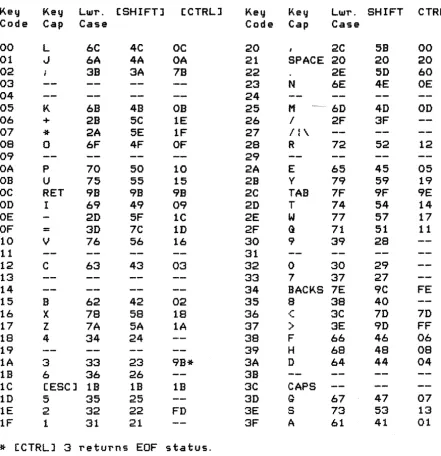
Then: If the resultant code is not a Screen Editor control code, and if the video inverse ~lag is set, then set bit 7 of the ATASCII code (will cause inverse video when displayed>,
KEY CODE TO ATASCII CONVERSION TABLE
Key Key LWT. [SHIFTJ [CTRLJ Key Key LWT. SHIFT CTRL
Code Cap Case Code Cap Case
00 L 6C 4C OC 20 2C 58 00
01 oJ 6A 4A OA 21 SPACE 20 20 20
02 3B 3A 7B 22 2E 5D 60
03 23 N 6E 4E OE
04 24
05 K 68 4B OB 25 M 60 40 00
06 + 2B 5C 1E 26 I 2F 3F
07
*
2A 5E 1F 27 11\08 0 6F 4F OF 28 R 72 52 12
09 29
OA P 70 50 10 2A E 65 45 05
OB U 75 55 15 2B Y 79 59 19
OC RET 9B 9B 98 2C TAB 7F 9F 9E
00 I 69 49 09 20 T 74 54 14
OE 2D 5F 1C 2E W 77 57 17
OF
=
30 7C 1D 2F G 71 51 1110 V 76 56 16 30 9 39 28
11 31
12 C 63 43 03 32 0 30 29
13 33 7 37 27
14 34 BACKS 7E 9C FE
15 8 62 42 02 35
a
38 4016 X 78 58 18 36 ,r
'- 3C 70 7D
17 Z 7A 5A lA 37 ) 3E 9D FF
18 4 34 24 38 F 66 46 06
19 39 H 68 48 08
1A 3 33 23 9B* 3A 0 64 44 04
18 6 36 26 3B
lC (ESC] 1B lB
is
3C CAPS10 5 35 25 30 Q 67 47 07
lE 2 32 22 FD 3E S 73 53 13
1F 1 31 21 3F A 61 41 01
*
(CTRLJ 3 returns EOF status.A complement o-f! this table (ATASCII to keystroke) is given in Appendix F.
[image:38.618.74.515.159.614.2]Dis p I a V Ha n dIe 1" ( S: )
The display device is a read/write device with a handler that supports the following CIa functions:
OPEN CLOSE
GET CHARACTERS GET RECORD PUT CHARACTERS PUT RECORD
GET STATUS <null function) DRAW
FILL
The Display Handler can produce the following error statuses:
$84 Invalid special command. $80 Cursor out-of-range. $91 Screen mode> 11.
$93 Not enough memory for screen mode selected.
The Display Handler is one of the resident handlers, and
therefore has a set of device vectors starting at location E410.
Screen Modes
You can operate the display screen in any of 20
configurations <modes 1 through 8, with or without split screen; plus mode 0, and modes 9 through 11 without split screen>. Mode 0 is the text displaying mode. Modes 1 through
11 are all graphics modes <although modes 2 and 3 do display a sub set of th e ATASC I I c harac tel" set>. Mod es 9 thr oug h 11
re~uire a GTIA chip to be installed in place of the standard
CTIA chip.
TEXT MODE 0
In text mode 0 the screen is comprised of 24 lines of 40
characters per line. Program alterable left and right margins limit the display area. They default to 2 and 39 <of a possible 0 and 39).
A program-controllable cursor shows the destination of the next character to be output onto the screen. The cursor is visible as the inverse video representation of the current character at the destination position.
The text screen data is internally organized as variable length logical lines. The internal representation is 24 lines when the screen is cleared. Each EOL marks the end of a logical line as text is sent to the screen. If more than 3 physical lines of text are sent, a logical line will be formed every 3 physical lines. The number of physical lines used to comprise a logical line (1 to 3) is always the minimum required to hold the data for that logical line.
The text screen "scrolls" upward whenever a text line at the
bottom
row
of the screen extends past the right margin, or a text line at the bottom row is terminated by an EOL. Scrolling removes the entire logical line that starts at the top of the screen, and then moves all subsequent lines upward to fill in the void. The cursor also moves upward, if the logical line deleted exceeds one physical line.All data going to or coming from the text screen is represented in a-bit ATASCII code as shown in Appendix E.
TEXT MODES 1 AND 2
In text modes 1 and 2 the screen comprises either 24 lines of 20 characters <mode 1), or 12 lines of 20 characters <mode 2). The left and right margins are of no consequence in these modes and there is no visible cursor. There are no logical lines associated with the data and in all regards these modes are treated as
graphics modes by the handler.
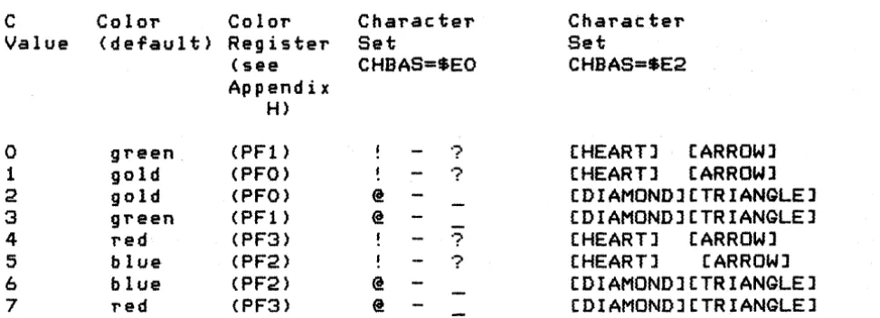
Data going to or coming from the screen is in the form shown below:
7
o
+-+-+-+-+-+-+-+-+
C D
+-+-+-+-+-+-+-+-+
C
Valueo
1 2 34
5 6 7 Color (default) green gold gold green red blue blue red Color Register (see Appendix H) (PF1) (PFO) (PFO) (PF1) (PF3) (PF2) (PF2) (PF3) Character Set CHBAS=$EO @ @ @ @ ? ??
? Character Set CHBAS=SE2[HEART] [ARROW]
[HEART] [ARROW]
[DIAMOND] [TRIANGLE] [DIAMOND] [TRIANGLE] [HEART] [ARROW]
[HEART] [ARROW]
[DIAMOND] [TRIANGLE] (DIAMOND] (TRIANGLE]
D is a 5-bit truncated ATASCII code that selects the specific character within the set selected by the C field. See Appendix E for the graphics representations of the characters.
Data base variable CHBAS [02F4] allows for the selection of either of two data sets. The default value of SEO provides the capital letters, numbers and punctuation characters; the
alternate value of $E2 provides lowercase letters and the special character graphics set.
Figure 5-5 Text Modes 1 and 2 Data Form
GRAPHICS MODES (Modes 3 Through 11)
The screen has varying physical characteristics for each of the graphics modes as shown in Appendix H. Depending upon the mode, a
1 to 16 color selection is available for each pixel and the screen size varies from 20 by 12 <lowest resolution) to 320 by 192 (highest resolution) pixels.
There is no visible cursor for the graphics mode output.
Data going to or coming from the graphics screen is represented as 1 to a-bit codes as shown in Appendix H and in the GET/PUT diagrams following.
SPLIT-SCREEN CONFIGURATIONS
In split-screen configurations, the bottom of the screen is reserved for four lines of mode 0 text. The text region is controlled by the Screen Editor, and the graphics region is
controlled by the Display handler. Two cursors are maintained in this configuration so that the screen segments can be managed independently.
[image:41.617.51.538.58.234.2]To operate in split-screen mode, the Screen Editor must ~irst be opened and then the Displa~ Handler must be opened using a
separate IOCB (with the split-screen option bit set in AUX1).
CIa Function Descriptions
The device-speci~ic characteristics o~ the standard CIa ~unctions
(described earlier in this section) are detailed below:
OPEN
The device name is 5, and the handler ignores any device number anl
~ilename speci~icationl i~ included.
The handler supports the ~ollowing options:
AUXl
7
o
+-+-+-+-+-+-+-+-+
:C:S:W:R:
+-+-+-+-+-+-+-+-+
Where: C
=
1 indicates to inhibit screen clear on OPEN.S
=
1 indicates to set up a split-screen con~iguration (~ormodes 1 through 8 only).
Rand Ware the direction bits (read and write).
AUX2
7
o
+-+-+-+-+-+-+-+-+ I mode
+-+-+-+-+-+-+-+-+
Where: mode is the screen mode (0 through 11).
Note: I~ the screen mode selected is 0, then the AUXl C and S options are assumed to be
O.
You share memory utilization with the Displa~ Handler
in~ormation. Sharing is necessary because the Display Handler dynamically allocates high address memory for use in generating the screen display, and because di~Terent amounts oT memory are needed for the different screen modes. Prior to initiating an OPEN command the variable APPMHI
(OOOE]
should contain the highest address oT RAM you need. The Screen handlerwill open the screen only i~ no RAM is needed at or below that address.
As a result of every OPEN command, the following screen variables al'e a I tel'ed:
The text cursor is enabled (CRSINH = 0). The tabs are set to the de Ta u I t s e t tin g s (2 and 39). Th e color reg i s t e r s are set to the default values (shown in Appendix H).
Tabs are set at positions 7,15,23,31,39, 47,55,63,71,79,87,95,103,111,119.
CLOSE
No special handlel' actions.
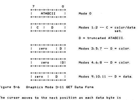
GET CHARACTERS and GET RECORD
Returns data in the Tollowing screen mode dependent Torms, where
each byte contains the data for one CUl'SOl' position <pixel); thel'e is no facility for having the handler return packed graphics data.
Figure 5-6
7
o
+-+-+-+-+-+-+-+-+ ATASCII
+-+-+-+-+-+-+-+-+
+-+-+-+-+-+-+-+-+
C D
+-+-+-+-+-+-+-+-+
+-+-+-+-+-+-+-+-+ zero : D : +-+-+-+-+-+-+-+-+
+-+-+-+-+-+-+-+-+
zero :D:
+-+-+-+-+-+-+-+-+
+-+-+-+-+-+-+-+-+
: zero D
+-+-+-+-+-+-+-+-+
Mode 0
Modes 1,2 -- C
=
color/data set.D = truncated ATASCII.
Modes 3,5,7 -- D
=
color.Modes 4,6,8 -- D
=
color.Modes 9,10,11 -- D = data.
Graphics Mode 3-11 GET Data Form
The cursor moves to the next position as each data byte is
returned. For mode 0, the cursor will stay within the specified margins; for all other modes, the cursor ignores the margins.
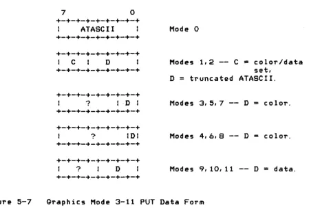
[image:43.617.40.519.320.665.2]PUT CHARACTERS and PUT RECORD
The handler accepts display data in the following screen mode
dependent forms; there is no facility for the handler to receive
graphics data in packed form.
Figure 5-7
7
°
+-+-+-+-+-+-+-+-+
ATASCII
+-+-+-+-+-+-+-+-+
+-+-+-+-+-+-+-+-+
C
D
+-+-+-+-+-+-+-+-+
+-+-+-+-+-+-+-+-+
? I -D I
+-+-+-+-+-+-+-+-+
+-+-+-+-+-+-+-+-+
? IDI
+-+-+-+-+-+-+-+-+
+-+-+-+-+-+-+-+-+
?
D
+-+-+-+-+-+-+-+-+
Mode 0
Modes 1,2 -- C
=color/data
set,
D
=truncated ATASCII.
Modes 3,5,7 -- D
=
color.
Modes 4,0,8 -- D
=
color.
Modes 9,10,11 -- D
=
data.
Graphics Mode 3-11 PUT Data Form
NOTE: For all modes, if the output data byte
e~uals$9B (EOL), that
byte will be treated as an EOL character; and if the output
data byte
e~uals$7D (CLEAR) that byte will be treated as a
screen-clear character.
The cursor moves to the next cursor position as each data byte is
written. For mode
0,the cursor will stay within the specified
margins; for all other modes, the cursor ignores the margins.
While outputting, the Display Handler monitors the keyboard to
detect the pressing of the [CTRLJ
1key combination. When this
occurs, the handler loops internally until that key combination
is pressed again:
This effects a stop/start function that
freezes the screen display.
Note that there is no ATASCII code
associated with either the [CTRLJ
1key combination or the
[image:44.615.98.548.135.450.2]GET STATUS
No handler action except to set the status to $01.
DRAW
This special command draws a simulated "straight" line from the current cursor position to the location specified in ROWCRS
[0054J and COLCRS [0055J. The color of the line is taken from the last character processed by the Display Handler or Screen Editor. To force the color, store the desired value in ATACHR [02FBJ. At the completion of the command, the cursor will be at the location specified by ROWCRS and COLCRS.
The value for the command byte for DRAW is $11.
FILL
This special command fills an area of the screen defined by two lines with a specified color. The command is set up the same as in DRAW, but as each point of the line is drawn, the routine scans to the right performing the procedure shown below (in PASCAL notation):
WHILE PIXEL [ROW,COLJ
=
0 DO BEGINPIXEL [ROW,COLl := FILDATi COL := COL
+
liIF COL) Screen right edge THEN COL 0 END;
An example of a FILL operation is shown below:
Where:
'-'
+---+
+---+
4
+---+
+
+ 2
represents the fill operation.
+
1+
'+' are the line points, with '+' for the endpoints.
1 set cursor and plot point.
2 set cursor and DRAW line.
3 set cursor and plot point.
4 set fill data value, set cursor, and FILL.
FILDAT [02FD] contains the fill data, and ROWCRS and COLCRS contain the cursor coordinates of the line endpoint. The value in ATACHR [02FB] will be used to draw the line; ATACHR always contains the last data read or written, so if the steps above are followed exactly, ATACHR will rtot have to be modified.
The value for the command byte for FILL is $12.
User-Alterable Data Base Variables
Certain functions of the Display Handler re~uire you to
examine and/or alter variables in the
as
database. The following describes some of the more commonly used handler variables. (see Appendix L, Bl-55, for additional descriptions).Cursor Position
Two
variables maintain the cursor position for the graphicsscreen or mode 0 text screen. ROWCRS [0054] maintains the display row number; and COLCRS [0055] maintains the display column
number. Both numbers range from 0 to the maximum number of
rows/columns, - 1. The cursor can be set outside of the defined text margins with no ill effect. You can read and write this
region. The home position (0,0) for both text and graphics is the upper left corner of the screen.
ROWCRS is a single byte. COLeRS is maintained at 2-bytes, with the least significant byte being at the lower address.
When you alter these variables, the screen representation of the cursor will not move until the next I/O operation involving the display is performed.
Inhibit/Enable Visible Cursor Display
You can inhibit the display of the text cursor on the screen by setting the variable CRSINH [02FO] to any nonzero value. Subsequent I/O will not generate a visible cursor.
You can enable the display of the text cursor by setting CRSINH to zero. Subsequent I/O will then generate a visible cursor.
Text Margins
The text screen has user-alterable left and right margins. The OS sets these margins to 2 and 39. The variable LMARGN [0052]
rightmost margin value is 39.
The margin values inclusively define the useable portion of the screen for all operations in that you do not explicitly
alter the cursor location variables as described prior to this paragraph.
Color Control
The OS updates hardware color registers using data from the
as
data base as part of normal Stage 2 VBLANK processing (see Section 6). Shown below are the data base variable names. the hardware register names, and the function of each register. See Appendix H for the mode dependent uses for the registers.Data Base Hardware Function
COLORO COLPFO PFO Playfield O.
COLOR 1 COLPFl PF1 Playfield 1.
COLOR2 COLPF2 PF2 Playfield 2.
COLOR3 COLPF3 PF3 Playfield 3.
COLOR4 COLBK BAK Playfield bac kground.
PCOLRO COLPMO PMO Player/missile O.
PCOLR1 COLPMl PM1 Player/missile 1.
PCOLR2 COLPM2 PM2 Player/missile 2.
PCOLR3 COLPM3 PM3 Player/missile 3.
Theory of Operation
The Display Handler automatically sets up all memory resources required to create and maintain the screen display at OPEN time. The screen generation hardware requires that two distinct data areas exist for graphics modes: 1) a display list and 2) a
screen data region. A third data area must exist ror text modes. This data area defines the screen representation for each of the text characters. Consult the ATARI Home Computer
Hardware Manual for a complete understanding or the material that is to follow.
The simplified block diagram below shows the relationships
between the memory and hardware registers used to set up a screen display (without player/missile graphics) by the
as
Note that the hardware registers allow for many other possibilities.DATA BASE VARIABLE
+---+
MEMTOP+
+
+---+---+
+---+
HARDWARE REGISTER
(Updated every VBLANK)
I
+---+
c c c c
+---+-+---+ +---+
+---+ :
Display SDLSTL DLISTL t c
t t
List
+
+---)+
+-+
=
=
SDLSTH+---+ +---+
+---+
Screen Data 1<-- SAVMSC= = + +
Graphics and/or
Text
+---+
End of RAM memory+---+
DLISTH
+---+
+---+
+---+
+---+
t CHBAS=EO 1---)1 CHBASE +---+
+---+
+---+
+---+---+
I Specials andt EOOO : Numbers
+---+
: Capital El00
1 Letters
+---+
I Special E200
: Graphics
+---+
I Lowercase E300
I Letters
+---+ +---+
COLOR 0•
I COLPFO= =--)1 COLPFl
COLOR 1 COLPF2
COLOR 2 COLPF3
COLOR 3 COLBK
COLOR 4
+---+
[image:49.617.47.543.61.745.2]+---+
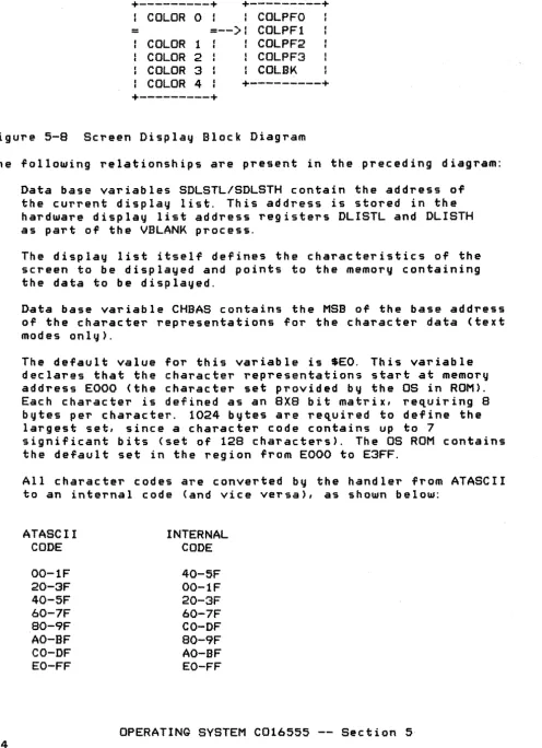
Figure 5-8 Screen Display Block Diagram
The following relationships are present in the preceding diagram:
1. Data base variables SDLSTL/SDLSTH contain the address of the current display list. This address is stored in the hardware display list address registers DLISTL and DLISTH as part of the VBLANK process.
2. The display list itself defines the characteristics of the screen to be displayed and points to the memory containing the data to be displayed.
3. Data base variable CHBAS contains the MSB of the base address of the character representations for the character data (text modes only).
64
The default value for this variable is $EO. This variable declares that the character representations start at memory address EOOO (the character set provided by the OS in ROM). Each character is defined as an 8X8 bit matrix, requiring 8
bytes per character. 1024 bytes are re,uired to define the largest set, since a character code contains up to
7
significant bits (set of 128 characters), The OS ROM contains the default set in the region from EOOO to E3FF.
All character codes are converted by the handler from ATASCII to an internal code (and vice versa), as shown below:
ATASCII CODE
00-IF 20-3F 40-5F 60-7F 80-9F
AO-SF CO-DF
EO-FF
INTERNAL CODE
40-5F 00-IF
20-3F
60-7F
CO-OF
80-9F
AO-BF EO-FF
The character set in ROM is ordered by internal code order. Three considerations differentiate the internal code from the external
(ATASCII) code:
ATASCII codes for all but the special graphiCS characters
were
to be similar to ASCII. The alphabetic, numeric, and punctuation character codes are identical to ASCII.In text modes 1 and 2 it was desired that one character subset include capital letters, numbers, and punctuation and the other character subset include lowercase letters and special graphics characters.
The codes for the capital and lowercase letters were to be identical in text modes 1 and 2.
Database variables COLORO through COLOR4 contain the current color register assignments. Hardware color registers receive these values as part of the stage 1 VBLANK process,