~AT.T
Comcode 501013270 Catalogue Number 999-300-652 Issue 1, December 1989730 Multi-Tasking
Graphics Terminal
To Order Copies of This Guide
Contact: Your AT& T Information Systems Account Team Or
Call: AT& T Technologies, Inc. on 800-432-6600 Or
Write: AT& T Customer Information Center P.O. Box 19901
Indianapolis, Indiana 46219
Order: Document No. 999-300-652, Issue 1 Comcode 501013270
Copyright © 1989 AT&T All Rights Reserved
WARNING
This equipment generates, uses and can radiate radio frequency energy and if not installed and used in accordance with the
instructions manual, may cause interference to radio communications. It has been tested and found to comply with the limits for a Class A computing device pursuant to Subpart J of Part 15 of the FCC Rules, which are designed to provide reasonable protection against such interference when operated in a comm~rcial environment. Operation of this equipment in a residential area is likely to cause interference in which case the user at his own expense will be required to take whatever measures may be required to correct the interference.
CANADIAN DOC COMPLIANCE INFORMATION This digital apparatus does not exceed the Class A limits for radio noise emissions set out in the Radio Interference Regulations of the Canadian Department of Communications.
Le present appareil numerique n'emet pas de bruits radioelectriques depassant les Iimites applicables aux appareils numeriques de la classe A prescrites dans Ie Reglement sur Ie brouillage radioelectrique edicte par Ie ministere des Communications du Canada.
NOTICE
Contents
Overview
About This Manual 1-1
Audience 1-1
730 MTG Pocket Reference Card 1-1
Conventions 1-2
Reader Response Card 1-2
Roadmap 1-3 For a New User 1-3
For an Experienced User 1-4
About the 730 MTG Terminal 1-5
Environment Needed 1-8 Hosts 1-8
UNIX® Releases 1-8 Software 1-9
630 MTG Software Development Package 1-9 5620 DMD Core Package 1-9
Hardware 1-10
Standard Components 1-10
Cables 1-11
Documentation 1-13
Getting Started
In This Chapter 2-1Installation 2-2
Inventory 2-2
Choosing a Worksite 2-3 Installation Procedure 2-4
Power On 2-9
Automatic Self test 2-9 Screen Appearance 2-10
Screen Saver Feature 2-11
Adjustments 2-12
Brightness and Contrast 2-12
Tilt and Swivel 2-12
Mouse and Menu Operation
In This Chapter 3-1For a New User 3-1
For an Experienced User 3-1 Using the Mouse 3-2
Mouse Cursor 3-2 Mouse Buttons 3-2 Mouse Actions 3-3 Using the Menus 3-4 Pop Up Menus 3-4 Static Menus 3-5 Scrolling Menus 3-6 Exercise 3-8
Mouse and Menu Quick Reference 3-9
Setup
In This Chapter 4-1
For a New User 4-1
For an Experienced User 4-1
What is Setup? 4-2
To Initiate Setup 4-2
Setup Main Menu 4-4
Viewing and Modifying Options 4-4
Ports 4-6
Host Port (default for Main, Main2) 4-6 Printer Port (Default for Aux) 4-16
SSI 4-17
Printer 4-18
Display 4-19
Keyboard 4-21
Mouse 4-23
Selftest 4-25
Default 4-26
Table of Terminal Option Defaults 4-27
Table of Terminal Option Defaults, continued 4-28
Exiting Setup 4-29
Exercise 4-30
Setup Quick Reference 4-32
Windows
In This Chapter 5-1
For a New User 5-1
For an Experienced User 5-1
Windows 5-2
Layers versus Non-Layers 5-2
Multiple Windows 5-4
Current Window 5-5
Mouse Cursors in Windows 5-6
The Main Terminal Menu 5-7
Window Commands 5-9
New 5-9
Reshape 5-11
Move 5-13
Top 5-15
Bottom 5-15
Current 5-17
Top and Current 5-17
Delete 5-18
Exit 5-19
Local Windows 5-20
Automatic Windows Screen Configuration 5-21
The Config File 5-24
Windows Quick Reference 5-25
The Wproc+ Emulator
In This Chapter 6-1 For a New User 6-1For an Experienced User 6-1 What is Wproc+? 6-2
Entering Wproc+ 6-2 Setup Options 6-4 Escape Sequences 6-5 Window Appearance 6-6 Text Area 6-6
Label Area 6-7
In-Window Status Line 6-9
The Scroll Area and Scrolling 6-10 Split Screen Feature 6-13
Using the Mouse in Wproc+ 6-15 Button 1 6-1 5
Button 2 6-15
Wproc+ Operations 6-17 Edit 6-17
Edit Operations 6-20 Font 6-23
Peel 6-24 Print 6-26 Options 6-27
Examples of Programming in Wproc+ 6-31 Programming the Label Area 6-31
Programming the Wproc+ Menu 6-32 Wproc+ Quick Reference 6-35
The 4014 GS Emulator
In This Chapter 7-1 For a New User 7-1For an Experienced User 7-1
What is the 4014 GS Emulator? 7-3 Entering the 4014 GS Emulator 7-3
Escape Sequences 7-5
Exiting the 4014 GS Emulator 7-6
Window Appearance 7-7
Scaled Windows 7-8 Clipped Windows 7-8
Alpha Mode 2-Column Display 7-8 Drawing Space Origin 7-9
The XV-Coordinate Space 7-9
Resolution 7 -10
Text, Vectors, Cursors, and Patterns 7 -11
Using the Keyboard in the 4014 GS 7-12
Using the Mouse in the 4014 GS 7-14
Button 1 7-14
Button 2 7-14
Button 3 7-15
The 4014 GS Menu 7-16
Character Size 7 -16
Options 7 -17
Drawing Functions 7 -24
Pixel Operations 7 -24
Alpha Mode 7-24
Graph Mode 7-25
Rectangle Draw 7 -28
Graphic Input (GIN) 7-31
GIN Data 7-31
GIN Request Command 7 -33
GIN Mode 7-33
Coordinate Conversion 7 -36
4014 GS Quick Reference 7-41
Printing
In This Chapter 8-1 For a New User 8-1
For an Experienced User 8-1 Printer Installation 8-2
Printer Setup 8-2
Printing Using the Menu 8-6
Printing Escape Sequences 8-8 Printer On 8-8
Printer Off 8-8 Media Copy On 8-9 Media Copy Off 8-9 Print Window 8-9
Print Termination Mode 8-10 Printer Extent Mode 8-10 Printer Status Request 8-10 Supported Printers 8-11
AT&T 5310/5320 Teleprinters 8-11 AT&T 475 and AT&T 476 8-13 AT&T 5721573 8-16
AT&T 582/583 8-17
AT&T 593 8-18
Printing Quick Reference 8-20
Label Window and PF Edit
In This Chapter 9-1For a New User 9-1
For an Experienced User 9-1 Label Window Description 9-2 Fkey Ranges 9-3
User and System Fkeys 9-5
Displaying the Label Window 9-6 On Power Up 9-6
From the More Submenu 9-7
Making the Labels Window Top and Current 9-8 Moving and Deleting the Labels Window 9-8 Programming the Fkeys 9-9
Using PF Edit 9-9
Using Escape Sequences 9-9 PF Edit 9-13
Entering PF Edit 9-14
Exiting PF Edit 9-15
Defining Labels and Strings 9-15
Label Window/PF Edit Quick Reference 9-17
Dial Edit
In This Chapter 10-1
For a New or Experienced User 10-1 Introducing Dial Edit 10-2
Entering Dial Edit 10-2 Exiting Dial Edit 10-4
Mouse Functions in Dial Edit 10-5 Button 1 10-5
Button 2 10-5
The Dial Edit Script 10-8 Editing a Script 10-9 Dial Edit Operations 10-10 Running a Script 10-10
Cancel/Terminate a Script 10-11 Monitoring a Script 10-12 Dial Edit Quick Reference 10-14
Maintenance and Troubleshooting
In This Chapter 11-1Care of the Terminal 11-2 Cleaning 11-2
Spills 11-2
Testing the Terminal 11-3 Automatic Selftest 11-3 User-Initiated Selftest 11-3 Selftest Option in Setup 11-3 Self test Error Messages 11-4 Testing the Mouse 11-7 Testing the Keyboard 11-8 Troubleshooting 11-9 Message Boxes 11-13
Customer Service Information 11-15
Appendix A: Control Characters
Wproc+ Control Characters A-14014 GS Control Characters A-4
Appendix B: Escape Sequence Reference
Wproc+ Escape Sequence Listing 8-1Character Attributes 8-1 Cursor Contents Report 8-2 Cursor Information Report 8-4 Editing Functions 8-7
Emulation Entrance 8-8 Font 8-9
Keyboard Support 8-9 Labels Window 8-9 Line Attributes 8-10
Programmable Options 8-10 Program 8-10
Program, continued 8-11 Printer 8-18
Requests, Reports, Resets 8-19 Scrolling Region 8-21
Status Line 8-21
4014 GS Escape Sequences 8-22
Appendix C: Character Sets and Fonts
Character Sets C-1Designating a Logical Set C-2
Mapping a Character Set to GL or GR C-4 Character Set Tables C-6
Font Information C-14 Resident Fonts C-14 Downloaded Fonts C-16
Appendix D: EtA Connections
Main and Main2 EIA Communications Interface 0-1 Aux EIA Communications Interface 0-3
SSI Port 0-5 LAN Port 0-6
Appendix E: 98-Key Keyboard
Keyboard Layout E-1
Transmitted Codes E-4
Numeric Keypad Transmitted Codes E-8
Appendix F: 102-Key Keyboard
Keyboard Layouts F-1Transmitted Codes F-4
Numeric Keypad Transmitted Codes F-8 Compose Mode F-9
Appendix G: 102+1-Key Keyboard
Keyboard Layout G-1Transmitted Codes G-3
Transmitted Codes G-4
Numeric Keypad Transmitted Codes G-9
Compose Mode G-10
Appendix H: 122-Key Keyboard
Keyboard Layout H-1Transmitted Codes H-4
Numeric Keypad Transmitted Codes H-9
Appendix I: Software Support
Host Software \-1AT&T Windowing Utilities \-1
Changes to Your .profile \-3
TERM Variable \-3
DMD and PATH Variables \-3 Terminfo \-5
TERM Variable \-5
730 Terminfo Entry \-5
Terminfo Listing \-6
Local 730 Terminfo Entry \-14
Terminfo for Fixed Non-Layers Window \-15
Appendix
J:
Options and Accessories
Listing J-1Figure 1-1 Figure 2-1 Figure 2-2 Figure 2-3
Figure 2-4 Figure 2-5 Figure ~-1 Figure 3-2 Figure 3-3 Figure 4-1 Figure 4-2 Figure 4-3 Figure 4-4 Figure 4-5 Figure 4-6 Figure 4-7 Figure 4-8 Figure 4-9 Figure 4-10 Figure 5-1 Figure 5-2 Figure 5-3 Figure 5-4 Figure 5-5 Figure 5-6 Figure 5-7 Figure 5-8 Figure 5-9 Figure 5-10 Figure 6-1 Figure 6-2
List of Figures
730 MTG Terminal
Attaching the Base to the Display Cable Connections
Adjusting Keyboard Position (except for 98-key Keyboard)
Window after Power On Tilt and Swivel
The Mouse Buttons Menu and Submenus Scrolling the Menu
Selecting Setup and the Setup Window The Setup Main Menu
Submenu and Settings Ports Submenu
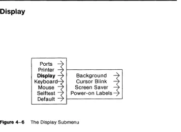
Printer Submenu The Display $ubmenu Keyboard Submenu Mouse Submenu Selftest Submenu Default Submenu The Window The Layers Icon
Mouse Cursors in Windows The Main Terminal Menu Creating a New Window Reshaping a Window Moving a Window
Top and Bottom Windows Local Windows
Windows generated by example 2config 1 file More Submenu
A Wproc+ Window
Figure 6-3 Figure 6-4 Figure 6-5 Figure 6-6 Figure 6-7 Figure 6-8 Figure 6-9 Figure 6-10 Figure 6-11 Figure 6-12 Figure 6-13 Figure 7-1 Figure 7-2 Figure 7-3 Figure 7-4 Figure 7-5 Figure 7-6 Figure 7-7 Figure 7-8 Figure 7-9 Figure 8-1 Figure 8-2 Figure 8-3 Figure 9-1 Figure 9-2 Figure 9-3 Figure 9-4 Figure 9-5 Figure 9-6 Figure 9-7 Figure 9-8 Figure 9-9 Figure 10-1 Figure 10-2 Figure 10-3 Figure 10-4 Figure 10-5 Figure 10-6 Figure 11-1 Figure E-1 Figure E-2 Figure F-1
xiv
The Label Area
Icons used in the Label Area Th e Scro II Area
Wproc+ Menu Selecting Text in Edit Edit Submenu The Send Operation Font Submenu Print Submenu Options Submenu
Vi Commands in the Wproc+ Menu More Submenu
A 4014 GS Window
Alpha Mode 2-Column Display The 4014 GS Menu
Character Size Submenu Options Submenu
Incremental Point Plot Mode DirectiQn Characters Rectangle Fill Patterns
The Crosshair Cursor
Setup Main Menu and Printer Submenu Ports Submenu
The Print Submenu
Label Window (general appearance) 122-Key Keyboard Labels
98-Key Keyboard Labels
102- and 1 02+1-Key Keyboard Labels Location of Label Window on Power Up More Submenu and Labels Option Keyboard Submenu
PF Edit Window showing Default User Fkeys PF Edit Option on the More Submenu The More Submenu and Dial Edit Option The Dial Edit Window
Dial Edit Menu Dial Edit Port Menu Running a Script The Monitor Window Expansion RAM Addresses 98-key Keyboard -- Main Keypad 98-key Keyboard -- Keypads 102-key Keyboard -- Main Keypad
Figure F-2
Figure G-1 Figure
G-2
Figure H-1 Figure H-2
102-key Keyboard -- Keypads F-3 1 02+1-key Keyboard -- Main Keypad G-2 102+1-key Keyboard -- Keypads G-3 122-key Keyboard -- Main and Function Key Keypads H-2 122-key Keyboard -- Keypads H-3
Table 1-1 Table 1-2 Table 7-1 Table 7-2 Table 7-3 Table 7-4 Table 8-1 Table 8-2 Table 8·--3 Table 8-4 Table 8-5 Table 8-6 Table A-1 Table A-2 Table A-3 Table C-1 Table C-2 Table C-3 Table C-4 Table C-5 Table C-6 Table C-7 Table C-8 Table C-9 Table C-10 Table 0-1 Table 0-2 Table E-1 Table E-2 Table E-3 Table E-4 Table E-5 Table F-1
List of Tables
Main, Main2 EIA Port Auxiliary EIA Port
Coordinate Conversion Chart Coordinate Conversion Chart Coordinate Conversion Chart Coordinate Conversion Chart 5310/5320 Options
475/476 Options 572/573 Options 582/583 Options 593 Options
593 Options, continued Wproc+ Control Characters Wproc+ Control Characters 4014 GS Control Characters
Character Set/Logical Set Escape Sequences Control Functions for Mapping Logical Sets United States ASCII Set
Un ited Kingdom Set Canadian/French Set
Special Character and Line Drawing Set Securities Industry Set
Mosaic Set ISO Latin-1 Set
ASCII Characters and Codes Main/Main2 Port Pin Definitions Auxiliary Port Pin Definitions Transmitted Codes
Transmitted Codes Transmitted Codes Transmitted Codes
Numeric Keypad Codes Transmitted Codes
Table F-2 Table F-3 Table F-4 Table F-5 Table F-6 Table F-7 Table F-8 Table F-9 Table F-10 Table F-11 Table F-12 Table G-1 Table G-2 Table G-3 Table G-4 Table G-5 Table G-6 Table H-1 Table H-2 Table H-3 Table H-4 Table H-5 Table H-6 xviii
Transmitted Codes Transmitted Codes Transmitted Codes Numeric Keypad Codes
Multinational Compose Characters
Multinational Compose Characters, continued Multinational Compose Characters, continued Multinational Compose Characters, continued Multinational Compose Characters, continued Multinational Compose Characters, continued Multinational Compose Characters, continued Transmitted Codes
Transmitted Codes Transmitted Codes Transmitted Codes Numeric Keypad Codes
Canadian/French Compose Characters Transmitted Codes
Transmitted Codes Transmitted Codes Transmitted Codes Transmitted Codes Numeric Keypad Codes
Chapter 1: Overview
Contents
About This Manual 1-1
Audience 1-1
730 MTG Pocket Reference Card 1-1
Conventions 1-2
Reader Response Card 1-2
Roadmap 1-3 For a New User 1-3
For an Experienced User 1-4
About the 730 MTG Terminal 1-5
Environment Needed 1-8 Hosts 1-8
UNIX® Releases 1-8
Software 1-9
630 MTG Software Development Package 1-9 5620 DMD Core Package 1-9
Hardware 1-10
Standard Components 1-10 Cables 1-11
Documentation 1-13
About This Manual
The 730 Multi-tasking with Graphics (MTG) Terminal User's Guide describes how to install, operate, and care for your 730 MTG Terminal. Appendices contain information on control characters, escape
sequences, font tables, keyboard layout and use, connections, software support, and options and accessories.
Audience
The intended user audience for this User's Guide is the technical professional with a broad range of experience. You could be a new user, or a software developer with previous experience using multi-tasking terminals. If you are experienced, you will notice that the 730 MTG Terminal is similar in operation to AT&T's 630 MTG Terminal. In any case, this Guide should give you enough information to learn how to use this terminal, and to supplement already existing knowledge. It is not the intent of this Guide to be a technical reference, although the Guide does contain technical information. Quick Reference pages are included in most chapters so you can begin using your terminal as quickly as possible.
730 MTG Pocket Reference Card
For those who are more experienced, the 730 MTG Pocket Reference Card contains more technical information. You will find this folded Card in the box containing this User's Guide.
About This Manual
Conventions
Physical switch settings are always in capital letters, such as ON or OFF.
Option settings are always in bold letters, such as visible or invisible.
Keyboard keys are capitalized or spelled outright, such as Control or CTRL.
Modes or states, such as Local Edit mode, are spelled with initial capital letters.
Items needing your special attention are called out in bold letters, such as Note or Caution.
Reader Response Card
You will find a blue Reader Response Card bound at the front of this manual. AT&T would appreciate hearing from you with your
comments on and suggestions for this publication. Be sure to note the manual name and order numbers on the line provided. This card is postage-free.
Roadmap
For a New User
This manual is ordered sequentially so that if you are a new user, you can learn to operate your terminal in a stepwise fashion, from
installation to use of more advanced features such as the Label Window and Dial Edit. You will encounter the following topics as you
read through this Guide:
• Chapter 1, Overview (What is the 730 MTG Terminal?)
• Chapter 2, Getting Started (Installation Information is located here)
• Chapter 3, Mouse and Menu Operation (Using your Terminal tools)
• Chapter 4, Setup (Assigning values to your Terminal's options)
• Chapter 5, Windows (Using the 730's Multi-tasking features)
• Chapter 6, The Wproc+ Emulator (your native environment)
• Chapter 7, The 4014 GS Emulator (For special graphics applications)
• Chapter 8, Printing (Printing a window or text)
• Chapter 9, Label Window and PF Edit (Programming your Function keys)
• Chapter 10, Dial Edit (Automating program sequences)
• Chapter 11, Maintenance and Troubleshooting (What to do when things go wrong)
Read Chapters 1, 2, and 3 before attempting to install and operate your terminal. Some chapters also contain exercises for practicing terminal skills.
Roadmap
For an Experienced User
If you have used multi-tasking terminals before, especially the AT&T 630 MTG Terminal, the operation of the 730 MTG will be easy and familiar. However, the 730 has many new features and enhancements for your convenience. Menus may contain new items you are not familiar with, and the Dial Edit feature, for instance, is totally new. Use the Quick Reference pages located at the back of many of this Guide's chapters to refresh your terminal skills. Then go on to learn new features as described in later chapters. The following chapters may be of special interest to you:
• Chapter 6, The Wproc+ Emulator
• Chapter 7, The 4014 GS Emulator
• Chapter 9, The Label Window and PF Edit
• Chapter 10, Dial Edit
More technical information is also contained in the Appendices.
About the 730 MTG Terminal
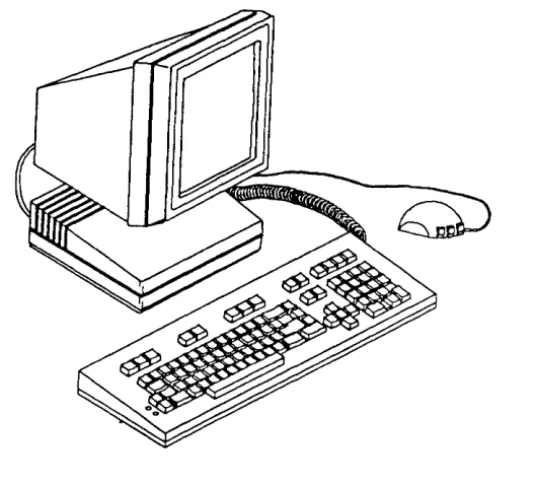
The 730 MTG Terminal is a high resolution, multi-window, multi-host, programmable graphics terminal. Its intelligence makes it ideal in application environments as diverse as software development, text preparation, engineering, and operations support systems.
Figure 1-1 730 MTG Terminal
One of the primary features of the 730 is its support of two terminal environments: layers and non-layers. In the 730's native non-layers environment, no special host support is required for normal terminal operation.
[image:26.456.110.378.183.426.2]About the 730 MTG Terminal
On a host running the UNIX® System V, the terminal's behavior is driven by its terminfo program description. See terminfo(4) in the UNIX® System V Programmer Reference Manual for further information on terminfo. The terminfo description for the 730 is given in the
Appendices.
In addition, software is available to allow downloading of
seJf-contained terminal application programs. In the layers environment, a window manager (described in Chapter 5) supports up to seven terminal sessions over a single host connection and an error-correcting protocol provides full support of downloadable applications.
A second feature of the terminal is the ability to support multiple, concurrent host connections. The 730 supports up to three EIA host connections at any given time, any of which may be in the layers environment. Additional connections are available if you use an optional SSI, StarLAN 10 ISO,or TCP/IP card.
Programmability is a third feature. You can create custom applications using the 630 MTG Software Development Package (previously available for the 630 MTG Terminal).
Others features include:
• Wproc+ Emulation
• Wproc+ compatibility with all AT&T 600-family terminal applications
• 4014 Graphics System Emulation
• International features including ISO Latin-1 and French/Canadian NRCS fonts and escape sequences; compose modes; and keyboard language options
• Auto Dial feature
• Label Window for specifying supported User and System function keys
• In-window status line
About the 730 MTG Terminal
• Access to StarLan 10 ISO with installation of an optional plug-in board
• Access to StarLAN 10 TCP/IP with installation of an optional plug-in board
• X-Windows capability when appropriately configured
• Mouse-operated menus for selection of terminal operations
• Text buffering and scrolling
• Selectable character sets including international fonts, and Mosaic, Securities, United Kingdom, and line drawing fonts
• Multiple resident fonts: small, medium, large and larger
• Local text printing capability
• 1024 by 1024 pixel display on a 16" CRT
• Choice of 98-, 102-, 102+1- (international), and 122-key keyboards
• Two RS 232-C ports for connection to external devices, up to three with an optional SSI card
• 10 MHz 68000 processor
• Up to 384 Kbytes of Read Only Memory (terminal control software)
• 640 Kbytes Random Access Memory standard
• 8 Kbytes non-volatile RAM for storage of terminal option
• Up to 384 Kbytes ROM in optional external cartridges for providing additional terminal capability
• RAM and 1/0 expansion capability via internal expansion connectors (see Options and Accessories Appendix);
• Time-selectable Screen Saver
• SSI connection with appropriate additional software.
Environment Needed
Hosts
The 730 can be used in the non-layers environment on any host computer or in the layers environment on any host that supports the AT&T Windowing Utilities package. For example, it is compatible for use in the layers environment on the AT&T 382 and 6386 families of computers.
UNIX® Releases
Although the 730 can be used without the aid of special software, it is more powerful when used with the AT&T Windowing Utilities package. The layers window manager, which is part of this package, is
described in Chapter 5.
The AT&T Windowing Utilities package is a standard utilities package delivered with UNIX® System V Release 3 (System V Release 2.1.1 for the 3820) and beyond. For UNIX® systems not containing the AT&T Windowing Utilities package, similar functionality can be obtained by installing the 5620 DMD Core package, described in the Appendix.
Note: For System V Release 3 and earlier releases, the AT&T
Windowing Utilities is designed for RS-232 connections. To run layers over networks may require additional host software (e.g., streams xt). See the appropriate 730 Network Access Unit documentation for more details.
Software
Software available for use with the 730 MTG Terminal includes:
630 MTG Software Development Package
Originally written for the 630 MTG Terminal, this package is
compatible with the 730 MTG Terminal. This package enables you to develop and execute downloadable terminal applications. It contains the 68000 C Compilation System, the application down loader,
terminal-specific library functions, development tools, and sample application programs.
5620 DMD Core Package
This package provides windowing support for use with UNIX® system releases prior to those containing the AT&T Windowing Utilities package.
Hardware
Standard Components
The ordering codes for the standard 730 MTG Terminal components are listed below. Optional cards and accessories are listed in the Appendix.
Item Comcode PECode
White Monitor 501006241 33534 Col10 Amber Monitor 501001697 33534 Col19 Controller /8ase 501013015 3344-730
Red Mouse 524594157 33536
White Mouse 524599875 33450
98-Key Keyboard 501009013 33401 102-Key Keyboard 501007421 33404 102+ 1-Key Keyboard 106075567 33405 122-Key Keyboard 501004881 33537
Hardware
Cables
[image:32.453.62.399.143.464.2]Interface cables needed for operation with the 730 MTG are described in the tables below.
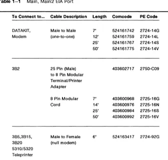
Table 1-1 Main, Main2 EIA Port
To Connect to ...
DATAKIT, Modem 382 385,3815, 3820 5310/5320 Teleprinter Cable Description
Male to Male (one-to-one)
25 Pin (Male) to 8 Pin Modular Terminal/Printer Adapter
8 Pin Modular Cord
Male to Female (null modem)
Length Comcode PE Code
7' 524161742 2724-14G 12' 524161759 2724-14L 25' 524161767 2724-14S 50' 524161775 2724-14V
403602717 2750-C09
7' 403600968 2725-16G 14' 403600976 2725-16N 25' 403600984 2725-16S 50' 403600992 2725-16V
6' 524163417 2724-92G
Note: In the table above, the cables can only be used for DC1/DC3 flow control. They cannot be used for RTS/CTS flow contro\.
Hardware
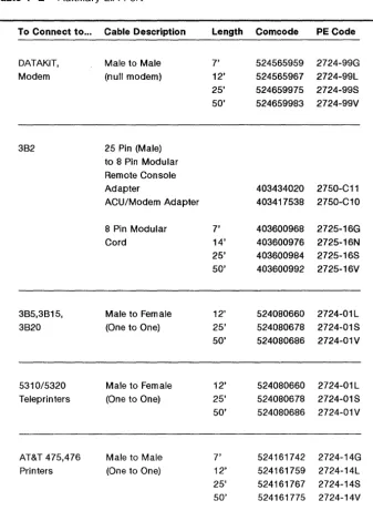
Table 1-2 Auxiliary EIA Port
To Connect to ...
DATAKIT, Modem 382 385,3815, 3820 5310/5320 Teleprinters AT&T 475,476 Printers Cable Description
Male to Male (null modem)
25 Pin (Male) to 8 Pin Modular Remote Console Adapter
ACU/Modem Adapter
8 Pin Modular Cord
Male to Female (One to One)
Male to Female (One to One)
Male to Male
(One to One)
1-12 730 MTG User's Guide
Length 7' 12' 25' 50' 7' 14' 25' 50' 12' 25' 50' 12' 25'
Comcode PE Code
524565959 2724-99G 524565967 2724-99L 524659975 2724-99S 524659983 2724-99V
403434020 2750-C11 403417538 2750-C10
403600968 2725-16G 403600976 2725-16N 403600984 2725-16S 403600992 2725-16V
524080660 2724-01L 524080678 2724-01S 524080686 2724-01V
524080660 2724-01 L 524080678 2724-01S 50' 524080686 2724-01 V
7' 12'
[image:33.456.42.379.85.555.2]Documentation
Available documentation for the 730 MTG includes:
• 730 MTG Terminal User's Guide (999-300-652)
• 730 MTG Terminal Pocket Reference Card (999-300-653)
• 630 MTG Software Development Package Release Notes (999-300-342IS)
• 630 MTG Software Development Guide (999-300-341 IS)
• 630 MTG Software Reference Manual (999-300-340)
• 630 MTG Application Toolchests (Utilities, applications, and accompanying documentation available from the AT&T UNIX System Toolchest, an electronic catalog. To browse or purchase, call the Toolchest computer on 201-522-6900. Login as guest.)
• 730 StarLAN 10 ISO 10 Network Access Unit User's Guide (999-300-624)
• 730 StarLAN 10 TCP/IP Network Access Unit User's Guide (999-300-660)
• 5620 Dot-Mapped Display Administrator Guide (999-801-1201S)
• 730 MTG Terminal Service Manual (available in 1990)
For pricing information on available 730-related documents, contact the Customer Information Center Commercial Sales Representative on:
1-800-432-6600
Chapter 2: Getting Started
Contents
In This Chapter 2-1
Installation 2-2 Inventory 2-2
Choosing a Worksite 2-3 Installation Procedure 2-4
Power On 2-9
Automatic Selftest 2-9 Screen Appearance 2-10 Screen Saver Feature 2-11
Adjustments 2-12
Brightness and Contrast 2-1 2 Tilt and Swivel 2-12
In This Chapter
Before you can use the 730 Multi-tasking with Graphics Terminal, you must install it. This chapter instructs you on unpacking, choosing a work site, installation, and cable connection.
Read and follow the procedures in this chapter before attempting to operate your terminal.
Installation
The sections that follow help you choose an appropriate location for your terminal, unpack and set up your terminal equipment, and make cable connections.
Inventory
Terminal equipment is packed in four separate cartons. Make sure you confirm your order with the PE Codes printed on the cartons. Observe any and all Caution and Warning labels on the cartons.
Note: To avoid condensation on the electronic components, allow the components to assume room temperature before unpacking.
The contents of the cartons correspond to items with PE Codes in the table of Standard Components in Chapter 1:
• Keyboard
• Mouse
• Controller Base/User's Guide/Pocket Reference Card
• Display
Installa tion
Choosing a Worksite
Choose a location for your terminal carefully. Consider its size, cable lengths, electrical requirements, and your own workspace needs. Position the display so that glare from outside or room lighting is minimized.
Try to avoid placing the terminal in dusty or dirty areas, fume-contaminated environments, or direct sunlight. Any of these factors could lead to high operating temperatures within the terminal that could result in terminal damage.
Placement within three feet of fluorescent lights or other sources of electrical interference may cause fluctuations in terminal performance.
Insta/la tion
Installation Procedure
Note: If you ordered optional accessories, refer to their User's Guides for installation information.
1 Unpack the controller base by lifting it from the carton by the foam packing pieces. Then remove the end pieces protecting the base. Place the controller/base at the location where you want the terminal.
2 If you purchased an optional accessory card, install it now. Refer to the document supplied with the card for installation procedures.
3 Attach the display to the controller/base following the steps below.
a Position the box with the correct side up.
b Remove the display (with the foam packing still around it) from its carton. Place the display with packing material next to the
controller/base. Orient the display with the screen downward and the bottom facing towards you.
c Spread open the plastic bag covering the display so that the four rectangular cutouts on the bottom of the display are clear. The
controller/base attaches to the display at these four pOints.
d Refer to Figure 2-1. Pick up the controller/base, rear side up. Insert the base swivel assembly tabs into the lower cutouts on the display. Pivot the controller base toward the display until the latches on the base snap into the upper display cutouts.
e Place the display and controller base in an upright position and remove the packing material and plastic bag.
Upper Cutouts
\
Lower Cutouts
Figure 2-1 Attaching the Base to the Display
Styrofoam
Pack
Installation
Ins ta lIa tion
AC Power Cord
Keyboard Cable
Mouse
4 Connect the display cable to the connector marked VIDEO on the controller/base. Secure the cable to the controller/base by tightening the two captive screws on the connector (see Figure 2-2).
5 Unpack the AC power cord from the display carton. Connect the female end of the power cord to the AC connector on the back of the display (see Figure 2-2).
10 Plate Cover
Drawer Latch
Display Cable
Filler Plate
Controller Drawer
Cable - - - . . . J J
Auxiliary Device Cable Modem or Direct Connect Cable
Figure 2-2 Cable Connections
6 Check that the AC power switch on the front of the display is off (the left side of the switch wi!! be
depressed). Insert the male end of the power cord into a 110 VAC outlet.
7 Remove the keyboard from its box and packing material. Make sure the keyboard you unpacked matches the keyboard identification codes (PE code and Comcode) on your packing slip.
Installation
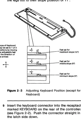
8 Adjust the keyboard to the desired position by
[image:44.456.108.370.143.529.2]adjusting the setting of the keyboard "feet". The slope setting of the feet can be positioned (tilted) by pushing them in the direction of the arrows as indicated in Figure 2-3. Keyboards can have two or three slope setting positions. For the 98-key keyboard, simply flip the legs out to their slope position of 11°.
Slope of Keyboard may be set to 1 of 3 positions by moving the adjustable feet In the direction of the arrows
+
Feet set for I---+-e~--t--~ maximum slope (12°)
Feet set for
~~~~~-r--mlddle slope (B,,)
~~~~~-t
__
Feet set for1= minimum slope (5")
Figure 2-3 Adjusting Keyboard Position (except for 98-key Keyboard)
9 Insert the keyboard connector into the receptacle marked KEYBOARD on the rear of the controller/base (see Figure 2-2). Push the connector straight in with the latch side down.
Installation
10 Unpack the mouse from its carton. Attach the mouse cable by lining up the pins on the connector with the mouse receptacle on the rear of the controller/base (see Figure 2-2). After connecting the cable, secure it by tightening the two retaining screws on the
connector.
11 Attach any interface cables to be connected to the MAINs and AUX ports by lining up the pins on the connectors with the corresponding receptacles on the rear of the controller/base. After connecting the cables, secure them by tightening the two retaining screws on each connector. Necessary interface cables were described in Chapter 1.
Power On
After connecting the terminal to a properly grounded and operating AC power source, press the right side of the ON/OFF switch. The green LED just above the ON/OFF switch will light.
If the ON/OFF switch does not light, make sure the switch is in the ON position and that the AC cord is connected at both ends. If the LED still does not light, notify your maintenance personnel.
Automatic Self test
Immediately after you "power on" the terminal, the
automatic
selftest
is executed. The terminal control software, program memory, andcommunication ports are tested. The time selftest lasts depends on how much memory is installed in your terminal. A tew seconds after power is applied the message, "Selttest", appears in the middle ot the screen along with the line, "730 MTG: Copyright (1989) - AT&T". It the selftest passes, the message, "Selftest passes", appears. Soon after, the user temporary (utemp) window and login prompt appear.
It needed, adjust brightness and/or contrast using the dials at the front ot the display (rotate controls to the right to increase, to the left to decrease.)
It self test tails, an error message describing which part of the test failed is displayed. Make a note of the error message, and reter to Chapter 11, "Maintenance and Troubleshooting", tor more instructions. Selftest continues, and when completed, displays the message,
"Selftest failed: Press any key to continue." If possible, the terminal resumes operations, creating a window based on Terminal Setup options. However, the portion ot the terminal that tailed selftest may affect the normal behavior of the terminal.
Power On
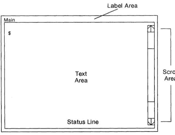
Screen Appearance
A window will appear on the screen after power on (see Figure 2-4) with an appearance determined by terminal Setup options. For more information on Setup and Windows, see Chapters 4 and 5.
Main
$
Text Area
Status Line
Figure 2-4 Window after Power On
2-10 730 MTG User's Guide
Label Area
[image:47.457.55.362.146.383.2]
Power On
Screen Saver Feature
The 730 MTG has a built-in screen-saver feature to help extend the life of the display. The display will go blank if neither the mouse nor keyboard is used for the time you select using the Screen Saver option under the Display submenu in Setup (see Chapter 4). You can elect to have your screen blanked after 1 to 60 minutes of non-use, or not at all (off option).
Caution: If the off option is selected, latent images may be
permanently left on the screen. Therefore, use of the off option is not recommended for extended periods of time.
To make the screen "viewable" again, press any key (SHIFT suggested) or simply move the mouse.
Adjustments
Brightness and Contrast
The brightness and contrast controls are located on the lower edge of the front of the display.
To increase the screen brightness, turn the brightness control wheel to the left. To decrease the brightness, turn it to the right.
Contrast is brightness of the characters relative to the brightness of the background. To increase screen contrast, turn the contrast control wheel to the right. To decrease the contrast, turn the wheel to the left.
Setting Brightness and Contrast
First turn the brightness and contrast wheels to their highest settings. You will see the "raster" pattern of the terminal. Next, turn the
brightness wheel to the right until the raster just disappears. Finally, turn the contrast control wheel until the display shows the contrast level you desire.
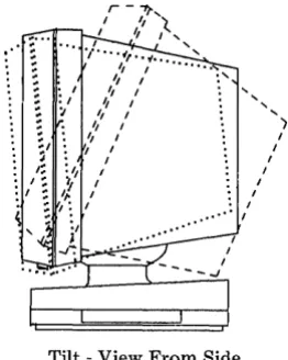
Tilt and Swivel
The display viewing position can be adjusted using the built-in tilt and swivel feature (see Figure 2-5).
Manually tilt the display forward or backward to a comfortable viewing position. The range of tilt motion is -5 to +20 degrees from true
horizontal.
Manually swivel the display left or right to the desired position. The swivel range of motion is 45 degrees in either direction.
r -"1f',
" ,:'
I~'
,
,./ ... ·t,.
'of... ' ",
I, ," I " I
" I
I, ,
"
,
I ,
,
I I , ,,
,
, I I•• ' I
Tilt - View From Side
Figure 2-5 Tilt and Swivel
' )
,
I,
Adjustments , , , ., ".', '. ,...
~..
[image:50.453.89.220.77.241.2]" ,
.... . .
.,"
... ,,' ... ,' ....
.
' .',
..
'.,;,' ' ... ,
....
')'.<.', '/ /
v
Swivel - View From Top
Getting Started
.'
Chapter 3: Mouse and Menu Operation
Contents
In This Chapter 3-1 For a New User 3-1
For an Experienced User 3-1
Using the Mouse 3-2
Mouse Cursor 3-2
Mouse Buttons 3-2
Mouse Actions 3-3
Using the Menus 3-4
Pop Up Menus 3-4
Static Menus 3-5
Scrolling Menus 3-6
ExerCise 3-8
Mouse and Menu Quick Reference 3-9
In This Chapter
The mouse is your primary tool for selecting terminal operations. Use the mouse to display menus (lists of terminal operations and options) and to select menu items. The mouse is also used as a pointing device to aid in window manipulation and scrolling (displaying menu items currently not seen).
For a New User
If you have never used a mouse before, read this chapter to familiarize yourself with mouse operation. The mouse cursor, functions, motion, and buttons are explained. The concept of menus is introduced. An exercise is provided at chapter's end to allow you to practice mouse and menu skills.
For an Experienced User
If you are familiar with mouse operation, you may want to skip this chapter. If you want to refresh mouse and menu skills, perform the exercise at the end of this chapter.
Using the Mouse
To operate the mouse, place the palm of your hand over the top of the mouse with your index, middle, and ring fingers resting on the three buttons. Without pressing any buttons, push the mouse back and forth on the work surface. It will roll on the rollerball imbedded in the bottom of the mouse.
Mouse Cursor
As you push the mouse back and forth on the work surface, notice the movement of the arrow (the mouse cursor) on the screen. Depending on terminal operations, the mouse cursor you see may be something besides an arrow. See Chapter 5 for a description of other mouse cursors.
Note that you can lift and reposition the mouse on the work surface without moving the mouse cursor.
To alter the perceived speed of mouse cursor movement in relation to actual mouse movement, change the Acceleration Option of the Mouse submenu under the main Setup menu. Set the option to off if you want the cursor to move at the same rate as the mouse itself. Set the option to on if you want to move the cursor across the screen with less actual mouse movement. See Chapter 4 for more information on the Acceleration option.
Mouse Buttons
There are three buttons on the mouse numbered consecutively, with button number one always associated with the index finger of the right or left hand (see Figure 3-1). To specify whether the mouse will be used with the right or left hand, set the Hand Option of the Mouse submenu under the main Setup Menu to right or left.
In general, Button 1 is used to point at and select terminal options, Button 2 is application specific and is assigned a function by the application, and Button 3 is a "command button" used to specify and select terminal/window options.
Using the Mouse
Figure 3-1 The Mouse Buttons
Mouse Actions
There are four distinct mouse actions involving movement and the mouse buttons:
• To press a button means to press it down and hold it
• To release a button means to let the button go
• To click a button means to press and release the button in quick succession
• To sweep (or "drag") the mouse means to press a mouse button; move the mouse on its roller; then release the button.
Depending on the application, you mayor may not see activity on the screen corresponding to each mouse action.
Using the Menus
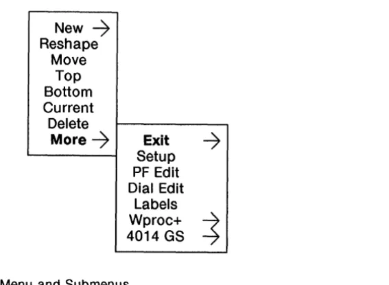
Menus are lists of terminal operations and options that ,may appear when you press mouse buttons or when you run applications (see Figure 3-2). You select menu items by positioning the mouse cursor and selecting with the mouse.
Items available for selection on the menu are displayed in normal intensity text. Items on the menu which are not allowed under the current conditions appear in grayed text. Items within a menu are highlighted in reverse video as the mouse cursor moves over them.
Menus associated with other menus in a hierarchical structure are called submenus. A submenu is indicated by an item name with a right-pointing arrow next to it (see Figure 3-2). To select a submenu, move the mouse cursor to highlight the desired submenu. To see and select Items from a submenu, move the mouse to the right,
highlighting the desired item, then release or click the appropriate mouse button. Selections are always made at the farthest right of the menu (where no more "arrowed" items appear).
Pop Up Menus
Menus that appear only while a mouse button is pressed are called pop up menus. For example, the Main Terminal Menu is a pop up menu. To select an item on a pop up menu, press the mouse button to display the menu, move the mouse to place the cursor over the desired menu item, which then becomes highlighted, and release the mouse button. A check may appear next to a selected item.
Using the Menus
New ~
Reshape Move
Top Bottom Current Delete
More~ Exit
~
SetupPF Edit Dial Edit
Labels Wproc+
~
[image:58.455.126.410.55.262.2]4014 GS
Figure 3-2 Menu and Submenus
Static Menus
Menus which remain on the terminal screen after a mouse button is released are called
static menus.
For example, the terminal Setup menu is a static menu. To select an item on a static menu, press and release the appropriate mouse button to display the menu, move the mouse cursor over the desired menu item, which then becomes highlighted, and click the appropriate mouse buttom. A check may appear next to a selected item.Using the Menus
Scrolling Menus
Only 16 items can be displayed on a menu at one time. If more than 16 items are available on the menu, a scroll area and scrolling bar will appear on the left side of the menu (Figure 3-3). Only the first 16 items will be shown. Since an item can only be selected if it is displayed, you must "scroll" through the items to display the one you want to select.
To scroll, place the mouse cursor over the scrolling bar and move it up or down until the desired item is displayed. Then move the cursor out of the scrolling area and move it over the item to be selected, which will then be highlighted. Select the item as described for a pop-up or static menu. The selected item will then appear "checked" on the menu.
Using the Menus
~
019
020
035
046
021
037
022
038
023
039
024
025
~
040
041
D
026
042
1.
2.
3.1. Place mouse cursor over scrolling bar.
2. Move scrolling bar until desired value is highlighted. 3. Select desired value.
Figure 3-3 Scrolling the Menu
Exercise
In this exercise, you will display the Setup menu (used in the next chapter) and practice making menu selections.
1 Press Button 3 to display the Main Terminal menu.
2 Move the mouse cursor until the More submenu is highlighted.
3 Move the mouse cursor to the right until the More Submenu appears.
4 Move the mouse cursor over the word Setup to highlight it. If Setup was not previously displayed, release the button to display a box outline of the Setup dialog box. Click mouse button 3 to display the Setup dialog box and the word "Setup" centered in a smaller box. If Setup was previously displayed and you release the button, the Setup box appears.
5 Click mouse button 1 with the mouse cursor on the small box labelled "SETUP" to display the Setup
static
main menu.6 Move the cursor over the Display submenu to highlight it. Move the cursor to the right until you see the submenu appear.
7 Move the cursor over the item Background to highlight it. Move the cursor to the right until you see the selections dark and light. The current setting will have a check mark next to it.
8 To change the current Background setting, move the cursor over the desired setting to highlight it. Click mouse button 1. Your screen should be either dark or light, depending on which option was chosen.
9 To exit from Setup, delete the Setup box (see "Delete," Chapter 5) or make another window Top and Current (see "Top," Chapter 5). Also see "Exiting Setup," in Chapter 4.
Mouse and Menu Quick Reference
If you are familiar with mouse and menu operation, use this quick reference page to remind you of basic procedures. For more detail, refer to the information in this chapter.
To
Change speed of mouse cursor
Change to a Right- or Left-hand Mouse
PRESS a Mouse button
RELEASE a Mouse button
CLICK a Mouse button
Sweep ("Drag") the Mouse
Display a Menu
Procedure
Change the setting of the Acceleration option on the Mouse submenu under the main Setup menu.
Set the Hand option of the Mouse submenu under the main Setup Menu to right or left.
Press and hold the Mouse button.
Let a Mouse button go.
Press and release the button in quick succession.
Press a mouse button, move the mouse on its roller, then release the button.
Press the appropriate Mouse button
Mouse and Menu Quick Reference
To
Display a Submenu
Select a Pop-up Menu item
Select a Static Menu item
Scroll a Menu
Procedure
Highlight the submenu name; move the mouse cursor in the direction of the arrow.
Press the appropriate mouse button to display the menu; move the mouse to place the cursor over the menu item; release the mouse button.
Press and release the appropriate mouse button to display the menu; move the mouse to place the cursor over the menu item; click the appropriate mouse button.
Place the mouse cursor over the scrolling bar and move the mouse cursor up or down until the desired item is displayed.
Chapter 4: Setup
Contents
In This Chapter 4-1
For a New User 4-1
For an Experienced User 4-1
What is Setup? 4-2
To Initiate Setup 4-2
Setup Main Menu 4-4
Viewing and Modifying Options 4-4
Ports 4-6
Host Port (default for Main, Main2) 4-6
Printer Port (Default for Aux) 4-16
SSI 4-17
Printer 4-1 8
Display 4-19
Keyboard 4-21
Mouse 4-23
Self test 4-25
Default 4-26
Table of Terminal Option Defaults 4-27
Table of Terminal Option Defaults, continued 4-28
Exiting Setup 4-29
Exercise 4-30
Setup Quick Reference 4-32
[image:65.462.24.383.69.342.2]In This Chapter
You may customize your terminal's functionality before you use it. This is called Setup. The terminal is already set with factory default
characteristics (options) which may require modification to take your network, hosts, and peripherals (such as printers) into account.
For a New User
This chapter uses mouse skills to set the options relating to your terminal's functionality. If you need to refresh mouse skills, review Chapter 3. You do not need window skills to use Setup; however, if you wish to modify the Setup window you must know how to
manipulate windows (Chapter 5). Before making changes to the Setup options, make sure you know about your network or host
configuration. Contact your System Administrator if you need help with this information.
For an Experienced User
If you are familiar with terminal option setup, this chapter will help you set the terminal's options using menus and the mouse as a pointing device.
What is Setup?
Setup is the feature that allows you to define your terminal's options and general operability. Items such as host and printer connections, keyboard functionality, and window and display appearance are determined using Setup. For instance, terminal option settings determine the appearance of the screen after the terminal is powered on.
Setup is a menu-driven window and is available from the Main Terminal Menu under the More submenu. You set your terminal options by displaying the Setup window and its static menu and making selections.
To Initiate Setup
To display the Setup menu, follow the steps below.
1 Press and hold mouse button 3 to display the Main Terminal Menu.
2 Position the mouse cursor over the More submenu, highlighting it.
3 Slide the mouse to the right until the More submenu is displayed.
4 Position the mouse cursor over the selection Setup, highlighting it. Release mouse button 3 (see Figure 4-1).
The outline of the Setup window will appear. If the Setup window was displayed previously, the Setup window appears immediately (becomes top and current.)
5 Move the mouse to position the window in the desired location. Since Setup menus are read from left to right, it is generally preferable to position the Setup window near the left side of the screen.
What is Setup?
Note: If desired, reshape the Setup window as explained in Chapter 5. If you reshape it to a size smaller than the
minimum size, the message box, "Swept window too small" will be displayed. Reshape the window to a larger size and click mouse button 3 again.
6 Click mouse button 3. The word "Setup" (centered in a small box in the window), terminal firmware date and version, and total amount of RAM will be displayed in the window (see Figure 4-1). The Setup window is top and current.
7 To display the Setup Main Menu, position the mouse cursor over the boxed word "Setup" and click mouse button 1.
The Setup Main Menu appears (see Figure 4-2). This menu, as well as its submenus, are
static,
which means they do not disappear when mouse buttons are released.New
--7
Reshape Move Top Bottom Current DeleteMore
--7
Exit--7
Setup PF Edit Dial EditLabels Wproc+
~
4014 GS
Figure 4-1 Selecting Setup and the Setup Window
8;8;8 ROMS
10/21/89
I
SETUPI
1152 K
BYTES RAM
Setup Main Menu
The Setup Main Menu consists of seven submenus that allow you to display the terminal options available and change them if desired. These submenus are Ports, Printer, Display, Keyboard, Mouse, Selftest, and Default.
Ports Printer Display Keyboard
Mouse Selftest Default
Figure 4-2 The Setup Main Menu
Viewing and Modifying Options
To see a submenu, position the mouse cursor on the submenu of choice, highlighting it. Then slide the mouse in the direction of the arrow. The submenu will appear.
Setup Main Menu
The items in the submenu consist of either other submenus or actual option choices. Slide the mouse in the direction of the arrow to display further submenus or option settings, such as on or off. The current setting for an option is indicated by a check mark in the menu next to the setting (see Figure 4-3).
To change a setting, position the mouse cursor over the desired setting, highlighting it, and click mouse button 1. A check will appear next to this setting. The new setting becomes active immediately unless otherwise noted in the option descriptions later in this chapter. Unavailable settings will appear in "grayed" text.
Ports Printer Display Keyboard
Mouse Selftest Default
Hand ~ Right Acceleration
-7
LeftFigure 4-3 Submenu and Settings
Ports
Ports Printer Display Keyboard
Mouse Selftest Default
Figure 4-4 Ports Submenu
Main Aux
~
Main2SSI
The Ports submenu allows you to define options for the selected physical ports. A port can be either a host port or a printer port. The Printer submenu maps the physical port as a printer port. Main and Main21 default to Host ports. Aux defaults to a printer port.
Host Port (default for Main, Main2)
Main is the main EIA port. Main2 is the additional main EIA port for a second host associated with the SSI card.
Note: Options marked with a
t
only apply to Wproc+ windows (see Chapter 6). [image:71.456.33.410.51.324.2]Ports
Speed is the operational speed of the port in bits per second. Match the selected speed with the speed of the attached modem or host. Speed ranges from 300 to 19200 bits per second. The default setting is 9600.
Send Parity determines the state of the eighth or ninth bit of sent data depending on the setting of the Bits/Character option. If parity=none, only the number of bits selected by the Bits/Character option is transmitted. If parity=odd or even, an additional bit is transmitted that indicates the parity of the data. If parity = mark, the additional bit is transmitted as a one. If parity = space, the additional bit is transmitted as a zero. The default setting is space.
Bits/Character determines the size of the data portion of each character (not including parity or start/stop bits). Characters can be 7 or 8 bits long. The default setting is 7.
Ports
Receive Flow Receive Flow selects whether Xon/Xoff or CTS are to be used as flow control. If Xon/Xoff is selected, software flow control is used. The terminal will stop sending characters when it receives a DC3 and resume sending characters when a DC1 is received.
When CTS is selected, hardware flow control is used. The CTS lead will be used to send data. CTS is not selectable on the Aux or Main2 port.
The default setting for this option is none.
In layers, the Receive Flow option is ignored unless the Encoding option is also enabled.
Caution: The Receive Flow option should normally be set to none unless the terminal is attached to a network or host which generates DC1/DC3 flow control. If this option is set to on and flow control is not available, an unintentional DC3 character may cause the terminal stop sending data to the host. If this occurs, set the option to none to restart transmission to the host.
Generate
Flow
Ports
Generate Flow selects Xon/Xoff or RTS to generate flow control for data transmission from a host or communications controller when in the non-layers environment. If Xon/Xoff is selected, the terminal automatically generates software flow control: an ASCII DC3 character when the internal buffer is almost full and an ASCII DC1 character when the buffer is almost empty.
When RTS is selected, hardware flow control is used. The RTS lead is used to receive data. RTS is not selectable on the Aux or Main2 port.
The default setting for this option is xon/xoff.
Generate Flow should be set to xon/xoff unless the host cannot handle DC1/DC3 characters. If this option is set to none, or if the host does not recognize flow control, data may be lost due to buffer overrun. When this happens, the terminal bell will ring.
Ports
Local Echo Set this option to on if you want keyboard data sent to the line and to the display at the same time. If off, keyboard data is sent to the host line only and must be "echoed back" by the host to be seen on the terminal. When local echo is off and there is no host connection, escape sequences are
ignored. The default setting is off.
UNIX operating system hosts generally require Local Echo set to off (or full duplex). For non-UNIX operating system hosts, change this option only if you are certain your host requires it. In layers, this option is ignored.
Encoding
Return
Ports
selects whether the data communications path will reliably transmit all 8-bit ASCII characters. Set Encoding to on if the communications system always transmits all 8-bit characters and uses ASCII DC1/DC3 or ENQI ACK control characters for internal flow control. The default setting is off.
Certain local area networks use ASCII control characters for internal signalling, and will not reliably transmit these characters. In layers, the protocol embeds ASCII control characters within messages. The communications system must be prevented from interpreting these characters. When Encoding is set to on, data transmitted by the terminal in layers is encoded to prevent any ASCII control characters from occurring. Data arriving from the host is also assumed to be encoded and is automatically decoded by the low level terminal 1/0 system.
Note: Data encoding reduces system throughput since it requires additional data
transmission.
determines what character is sent when the Return key is pressed. CR sends a carriage return (ASCII OxOd). CR/LF sends a carriage return followed by a line feed (ASCII OxOdOxOa). LF sends a line feed (ASCII OxOa). The default setting is CR.
The corresponding UNIX operating system stty flags are: for CR, -Igncr icrnl; for CR/LF, igncr icrnl; and for LF, -inlcr.
Ports
Received Newlinet
Power-on Position
Presence
determines what happens when a newline
character (ASCII OxOa) is received by the terminal. If this option is set to LF, the cursor will advance to the same position on the next screen line. If this option is set to CR/LF, the cursor will advance to the beginning of the next screen line. The default setting is LF.
allows you to create a window that automatically appears if you select the power-on/menu setting for the Presence option (below). When you select Power-on Position, a window outline appears based on the current default font and emulator. Move this window to the desired position on the screen. To save the window position, press mouse button 1 or 3. To cancel the operation, press mouse button 2.
allows you to select the appearance of your terminal on power-on. If Presence =
Power-on/Menu, the window created using the Power-on Position option (described above) appears and the name of the host port is displayed on the New and Exit Setup submenus on power-on. If Presence = Menu, the name of the host port appears on the New and Exit Setup submenus on power-on. If Presence = None, no window and no host name
appears on power-on. The default setting for this option in Main is Power-on/Menu. The default setting for this option in Main2, 881, or Aux is Menu.
Default Emulator
Default Fontt
Layers Columnst
Ports
determines what emulation is active on power on. If the Default Emulator is set to wproc+, the Wproc+ emulator will be active (see Chapter 6). If the Default Emulator is set to 4014GS, the
Tektronix-type 4014GS emulator will be active (see Chapter 7). The default setting is wproc+.
allows you to choose what font size is displayed on power-up. Choose from small, medium, large, and larger font sizes. The default setting for this option is large.
defines the number of columns of text displayed in new layers windows. The valid column range depends on the current font setting. This option also defines the number of columns used when determining the outline size for reshaped layers
windows. The default column setting is 80.
Ports
Layers Rowst
Non-layers Columnst
Non-layers Rowst
defines the numbe