Small scale/Large scale MFC Stacks for Improved
Power Generation and Implementation in Robotic
Applications
GEORGIOS PAPACHARALAMPOS
Faculty of Environment and Technology, University of the West of
England, Bristol
i
Abstract
Microbial Fuel Cells (MFCs) are biological electrical generators or batteries that have
shown to be able to energise electronic devices solely from the breakdown of
organic matter found in wastewater. The generated power from a single unit is
currently insufficient to run standard electronics hence alternative strategies are
needed for stepping-up their performance to functional levels. This thesis deals with
MFC miniaturisation; their proliferation into large stacks; power improvement by
using new electrode components and finally a novel method of energy harvesting
that will enhance the operation of a self-sustainable robotic platform. A new
small-MFC design was developed using 3D printing technology that outperformed a
pre-existing MFC of the same volume (6.25 mL) highlighting the importance of reactor
configuration and material selection. Furthermore, improvements were made by the
use of a cathode electrode that facilitates a higher rate of oxygen reduction reaction
(ORR) due to the high surface area carbon nanoparticles coated on the outer layer.
Consequently, a 24-MFC stack was built to simulate a small-scale wastewater
treatment system. The MFC units were connected in various arrangements, both
fluidically as a series of cascades and electrically in-parallel or in-series, for
identifying the best possible configuration for organic content reduction and power
output. Results suggest that in-parallel connections allow for higher waste removal
and the addition of extra units in a cascade is a possible way to ensure that the
organic content of the feedstock is always reduced to below the set or permitted
levels for environmental discharge. Finally, a new method of fault-proof energy
harvesting in stacks was devised and developed to produce a unique
energy-autonomous energy harvester without any voltage boosting and efficiencies above
ii
test platform which demonstrates energy autonomous behaviour and highlights the
iii
Declaration
This dissertation is the result of my own work and includes nothing which is the
outcome of work done in collaboration except where specifically indicated in the text
and bibliography. All material previously published in scientific journals, has been
iv
Glossary of Terms
ABS Acrylonitrile Butadiene Styrene
AC Activated Carbon
BES Bioelectrochemical Systems
BiBC Bristol BioEnergy Center
BOD Biological Oxygen Demand
BRL Bristol Robotics Laboratory
CCV Closed circuit Voltage
CD Current Density
COD Chemical Oxygen Demand
DET Direct Electron Transfer
D20 20-day period
D40 40-day period
EAB Electro-active Biofilm
ESR Equivalent in -Series Resistance
GDL Gas Diffusion Layer
HRT Hydraulic Retention Time
IEM Ion Exchange Membrane
LED Light Emitting Diode
MET Mediated Electron Transfer
MFC Microbial Fuel Cell
MOSFET metal–oxide–semiconductor field-effect transistor
MPL Micro porous layer
MPP Maximum Power Point
v
OCV Open Circuit Voltage
ORR Oxygen Reduction Reaction
PC-ISO medical-grade biocompatible Polycarbonate
PD Power Density
PMS Power Management Sytems
PTFE Polytetrafluoroethylene
RC25 Nanocure ceramic-filled photo curable resin
Re Reynolds number
Rext External Resistance
Rint Internal Resistance
s.a surface area
SEM Scanning Electron Microscope
TI Texas Instruments
TYE Trypton Yeast Extract
Contents
Abstract ... i
Glossary of Terms ... iv
Chapter 1 ... 1
Introduction and Background ... 1
1.1. Overview ... 1
1.2. Thesis outline ... 2
1.3. The Microbial Fuel Cell technology ... 5
1.3.1. History of MFCs ... 5
1.3.2. Main principles that render MFC operation used in this study ... 6
Objectives ... 15
Chapter 2 ... 17
2. Design and optimisation of MFCs ... 17
2.1. Miniaturising MFC reactors ... 17
2.1.1. Current prediction for small MFCs ... 17
2.1.2. Physical & biochemical advantages of small-sized MFCs ... 18
2.1.3. Reactor configuration of small-scale MFCs ... 19
2.2. Manufacturing materials of small MFCs ... 22
2.3 Materials and methods ... 23
2.3.1 Twist n’ Play MFC-chamber design and fabrication ... 23
2.4 MFC operation and monitoring ... 25
2.4.1 Inoculation and fuel supply ... 25
2.4.2 Power curves and data collection ... 26
2.4.3 Chemical Oxygen Demand (COD) ... 26
2.5 Results & Discussion ... 26
2.5.1 Performance from Individual new design MFCs ... 26
2.5.2 MFCs fluidically connected ... 31
2.5.3 COD reduction ... 36
2.6 Conclusions ... 38
Chapter 3 ... 41
3. Power increase in MFCs ... 41
3.1. Focus on cathode optimisation ... 41
3.2. Materials and Methods ... 42
3.2.2. Electrode materials ... 42
3.2.3. Anolyte-Anaerobic sludge ... 44
3.2.4. Data recording and processing ... 44
3.2.5. Polarisation experiment ... 45
3.2.6. Digital wristwatch, eZ430-Chronos ... 45
3.3. Results and Discussion ... 45
3.3.1. OCV mode and power performance under a load ... 45
3.3.2. Power output from individual MFCs... 47
3.3.3. MFC stacks (n=3) in-parallel and in-series ... 49
3.3.4. MFC stack (n=2) powering a practical application ... 53
3.4. Conclusions ... 55
Chapter 4 ... 58
4. MFC stacks for energy harvesting and wastewater treatment ... 58
4.1. Operational versatility of MFC stacks ... 58
4.1.1. Challenges in wastewater treatment ... 58
4.2. Materials & Methods ... 61
4.2.1. Microbial Fuel cell Stack ... 61
4.2.2. Switch box for electrical configurability ... 62
4.2.3. Cascade setup and isolated hydraulic scenarios ... 62
4.2.4. Operational parameters ... 65
4.2.5. Data logging ... 66
4.2.6. COD, pH and conductivity measurements ... 67
4.2.7. Polarisations sweeps ... 67
4.3. Results and discussion ... 68
4.3.1. Individual/stacked units fed independently (Stage 1) ... 68
4.3.2. Cascade operation scenarios ... 70
4.3.3. Overview of performance characteristics ... 108
4.3.4. Adaptation traits of MFC stacks ... 111
4.4. Conclusions ... 113
Chapter 5 ... 115
5. Improved energy harvesting in MFC stacks ... 115
5.1. Energy extraction from MFCs ... 115
5.2. Experimental ... 117
5.2.2. MFC stack reconfiguration & energy storage... 118
5.2.3. Data recording and processing ... 118
5.2.4. Possible electrical configurations and charging regimes ... 118
5.3. Results and discussion ... 120
5.3.1. Rate of charging from fixed configurations ... 120
5.3.2. Dynamic reconfiguration and fixed configuration charging times ... 121
5.3.3. Optimising energy harvesting ... 123
5.4. Conclusions ... 124
Chapter 6 ... 127
6. Fail-safe power management in MFC stacks... 127
6.1. Efficiency of power management systems (PMS)... 127
6.1.1. Cell reversal in MFCs and prevention ... 128
6.2. Experimental ... 131
6.2.1. MFC stack construction and operation ... 131
6.2.2. Data logging and processing ... 132
6.2.3. MFC stack digital switch converter ... 132
6.2.4. Selection of electrical configurations and switching intervals ... 133
6.3. Results and discussion ... 135
6.3.1. Performance of individual units (n=8) ... 135
6.3.2. Performance of electrical configurations... 136
6.3.3. Polarity reversal during charging in a series configuration ... 140
6.3.4. Energy extraction from both dynamic and fixed configurations ... 142
6.3.5. Optimising power transfer ... 146
6.3.6. Energy autonomous electronics for energy harvesting in MFC stacks ... 147
6.4. Conclusions ... 151
Chapter 7 ... 154
7. Developing an intelligent microbial electrical system ... 154
7.1. Knowledge transferability on a MFC testing platform: EcoBot-IV ... 154
7.2. Alternative PMS strategy ... 161
7.2.1. MPPT without the occurrence of cell reversal ... 161
7.2.2. Results and discussion ... 165
7.3. Concluding remarks ... 168
1
Chapter 1
Introduction and Background
1.1. Overview
Microbial Fuel Cells are an eco-friendly technology where anaerobic bacterial
species harvest energy from organic compounds and convert it to electrical energy
via their respiratory metabolism. Even though the MFC principle is over a hundred
years old, the ability of MFCs to extract energy stored in wastewater has lately
received the attention of the research community due to its advantages to aerobic
treatment processes and the generation of useful amounts of electricity. A MFC
resembles a galvanic cell hence it can be considered as a bio-battery with a
maximum theoretical open-circuit voltage (OCV), dictated by the redox potential
which can reach up to 1.14 V, whilst the operating voltage at maximum power
transfer (MPP), should be approximately half this value. The majority of electrical
circuits operate in the area of 1.5 V to 3 V, which is far from matching the output of
an MFC unit. Developments in electrode material and the concomitant
miniaturisation of MFCs have been the first step towards power optimisation. The
main strategy for increasing the performance of individual MFC units is by connecting multiple MFCs in stack configuration or with the use of a plethora of
DC-DC converting techniques for stepping-up the voltage from a single unit. To date,
findings from various research groups have advanced the knowledge in
miniaturisation and scaling-up of MFCs to the stage that can allow for the technology
to become of practical value, providing benefit of wastewater treatment,
2
Even though there is still the room for progress in increasing power density, the
technology is rapidly approaching real-world implementation and commercialisation.
Thus, the philosophy behind this thesis is under the contention that:
It is feasible to develop reliable MFC systems capable of dynamic
homeostasis, self-adjusting their performance to meet changes in the quality
of their fuel feedstock and regulating their energy output to match that
required for various functions.
1.2. Thesis outline
In an effort to provide a better understanding in the development of intelligent
MFC systems, the experimental work is divided in seven distinct but yet
interconnected chapters. The line of work involves miniaturisation of a single MFC
unit, followed by power improvement of units and their multiplication into stacks of
units.
Chapter 1 reports succinctly on the history of MFCs and the modus operandi
followed by the fundamental principles that render MFC stacks feasible. Building on
these foundations, the main objectives of this work are presented that move towards
the realisation of energy autonomous systems.
Chapter 2 investigates different 3D printed structural materials as well as the
reactor architecture of a novel MFC design (Twist n’ Play) in an effort to provide a better understanding in reactor miniaturisation. Due to a limited number of studies
reporting the effects that various thermo-polymer plastics have in MFC operation, this chapter reveals further aspects about the materials’ properties which are likely to
3
overall biocompatibility, selective electrical insulation and oxygen diffusion (low for
anode; high for cathode) for high power output. Results suggest that a better MFC
reactor design built with the right material can improve the performance.
Chapter 3 explores the theory that a higher surface area electrode can
significantly increase the rate of cathodic reactions and result in improved power
output. It is shown that the tested substratum used as an electrode in the cathode greatly enhanced the performance allowing the demonstration (for the first time)
of the powering of a digital wristwatch on-the-fly by just two small-scale MFCs
connected in-series.
Chapter 4 reports on the electrical and hydraulic repositioning of a 24 small-scale
MFC stack set in a cascade-like waste stream. This system is simulating in a small
scale, a series of possible continuous wastewater efflux scenarios with a
simultaneous electrical reconfiguration and how that affects the COD treatment to power ratio. Results provide further insight on the system’s internal resistance
variance when MFC units are repositioned in the cascade and also reveal for the first time the biofilm’s dynamic homeostatic ability to rebound from a high
internal resistance to a lower state based on the organic substrate supply that
reaches each cell in the cascade.
Chapter 5 highlights the significance of power management in MFC stacks and
elaborates on the efficient energy harvesting from MFCs. The undertaken works
reveals a novel and revolutionary analogue way of passive harvesting whereby
the progressive switching of parallel connections to series within a stack has
an almost 2-fold improvement in power output and halves the time required for
4
In Chapter 6, the findings from the previous chapter are used to develop an
automated system which allows for precise configuration switching with negligible
efficiency losses. Results reveal that the system extracts energy at high rates also
allows for smooth and robust operation by preventing cell reversals under low
external impedance conditions. This discovery further leads to the construction of
an energy autonomous circuitry, powered exclusively by MFCs, with the ability to
harvest energy and auto-configure the electrical connections within the stack for
optimal performance.
Chapter 7 examines the possible applicability of all the acquired knowledge onto
the latest generation of a self-sustainable robotic platform, EcoBot-IV. The
experimental plan concludes with an alternative approach in power control from MFC
5
1.3. The Microbial Fuel Cell technology
1.3.1. History of MFCs
A microbial fuel cell is a bio-electrochemical device that is capable of generating
bioelectricity. The first to examine the bioelectric phenomenon and the term
bioelectricity was Luigi Galvani in 1790, who noticed twitching of isolated frog leg
when a brief electrical discharge was passed through it 1. But the first MFC concept was demonstrated by Michael Cresse Potter in 1910 2. He produced electrical energy from living cultures of E s c h e r i c h i a c o l i and S a c c h a r o m y c e s s p by using platinum electrodes. In 1931, Barnet Cohen revived Potter’s idea by creating
the first stack of microbial fuel cells that were connected in-series, capable of
producing over 35 V, though only under a current of 2 mA 3. During the 1950’s, Rohrback et al., 4 designed a biological fuel cell in which Clostridium butyricum was used as a biological catalyst for generating hydrogen from glucose fermentation but
without generating any electrical energy. Microbial fuel cells became popular in the
late 1950s, when NASA showed interest in converting organic waste into electricity
on its long-distance space flights. However, these fuel cells did not produce sufficient
power, were not appealing to the market and soon disappeared. Later, during the oil
crisis of the 70s and 80s, the interest in the development of chemical fuel cells was
revived. In 1966, Williams 5 showed that chemical fuel cells powered by rice husk produced 40 mA at 6 V. Rice husk is rich in lignocellulose, which under fermentative
conditions yields many useful enzymes and biofuels like ethanol that could be used
in conventional fuel cells. In 1969, Yao et al.6 showed that glucose could be chemically oxidised in the presence of platinum and therefore used as a fuel. Karube
6
using Anabaena spp. as a biocatalyst, in which phosphoric acid was used as the electrolyte. The years that followed during the 1980s and the 1990s revealed
significant results that are discussed below as part of the small MFC operation in this
study.
1.3.2. Main principles that render MFC operation used in this study
1.3.2.1. Single chamber open-to-air cathode MFCs with mediator-less
anodophillic biofilms.
1.3.2.1.1. Mediator-less MFCs
For many years, MFC studies were unable to provide sufficient answers to why
the performance could not be sustained and improve any further. It was not until
1962 and 20 years later that work from various groups 8–11 noticed that the addition of synthetic electron mediators could benefit substantially the power output and
current density of MFCs. Bennetto’s group were the first to use this knowledge to
power a DC motor for a short period of time 12. Unless the bacteria were anodophillic, then their outer membrane layer acted as an insulator because it
consists of lipids, peptididoglycans and lipopolysaccharides that prevent electrons to
flow through 13–16. Electron shuttles are capable of being reduced (by NADH, NADPH or reduced cytochromes) within the membrane and oxidised at the anode, which
speeds the transfer of electrons from the bacteria membrane to the surface of the
electrode.
However, a real breakthrough was made when some microbes were found to
7
Rhodoferax ferrireducens can recover up to 83 % of electrons from glucose oxidation in the presence of Fe3+ without a mediator.
This discovery, along with a study in 2005 20, suggested that the use of artificial mediators in MFCs was less efficient than the already bacterial produced mediators
or the direct electron transfer (DET) from the membrane to the electrode. Since that
point, the use of added mediators in MFC studies was gradually avoided and the
majority of studies focused to mediator-less MFC operation.
1.3.2.1.2. Anodophillic bacteria and electroactive biofilms
The first bacteria to show bio-electrochemical activity of transferring electrons
directly by conductance through the membrane were Shewanella putrefaciens 19,21,
Geobacter sulfurreducens 22, Geobacter metallireducens 23 and Rhodoferax ferrireducens 17. In general, when a MFC is inoculated with a naturally occurring mixed culture, electrochemically active bacteria and other symbiotically related to
these bacteria are expected to establish an electroactive biofilm when they are
operated at Rext values matching the Rint, and decreases the number of methanogenic species 24,25. However, 16S rDNA sequencing analysis revealed an abundant phylogenetic diversity in the anode consortia with no single emergent
bacterial species. This randomness suggested the presence of other bacterial
strains, apart from the iron reducing species that contribute to electricity generation,
and correlates to the inoculum and substrate type used 26–32.
When conditions are favourable these electrogenic strains form a structural matrix
on the anode by attachment, called biofilm. This structure provides protection from
toxic agents. An additional layer of proteins, polysaccharides and ions called a
8
the substratum that allows it to firmly attach onto living organisms or solid surface
areas 33. In the latter case, the solid surface areas were shown to be carbon based or metal based electrodes that later revealed the direct electron transfer approach 22,23,34
. Hence electroactive biofilms (EAB) attached onto conductive surfaces are the
bacterial engine that is favoured throughout this experimental process.
1.3.2.1.3. O2-based cathodes
Diatomic oxygen gas (O2) constitutes 20.8% of the volume of atmospheric air and is the third-most abundant element on Earth, after hydrogen. It has the second
highest electronegative number which makes it a higly reactive chemical reaction
reagent. Because of its availability and high electronegativity, oxygen greatly favours
oxidation-reduction reactions (ORR). These are the most important reactions in fuel cells’ cathode electrode and facilitate the 4-electron reaction from O2 to H2O and the 2-electron reduction from O2 to H2O2 (hydrogen peroxide) 35. A large bottleneck in ORR is the low rate of reaction on the cathode. Various metals have typically been
used to catalyse the cathodic reaction 36 but reduction of oxygen at the cathode is currently an important limiting factor in a MFC. Hence, many studies suggested the
use of other chemicals such as ferricyanide as a terminal electron acceptor on the
cathode 37 that greatly improves the performance but at the expense of sustainability. When ferricyanide is reduced, then it is converted to ferrocyanide in a non-reversible
reaction. That involves the frequent replacement of ferricyanide in the cathode and
the safe disposal of ferrocyanide which renders this strategy as unsustainable and
9
Scaling up is a fundamental problem for practical applications of MFCs for
wastewater treatment and bioenergy production. The main challenges for
commercialising scalable MFCs are the development of materials that are
cost-effective, environmentally friendly, efficient in power generation but also identifying
architectures that can be used at a larger scale. Maximum power densities in most
high power MFCs are largely inhibited by cathode surface area and performance 40,41
, which together with the cost of cathode materials and proton exchange
membranes (PEM), can account for the greatest percentage (47%) of the MFC
capital costs 42. As such, this study has used of catalyst-free air cathodes and supports the notion for longevity and low cost cathode electrodes.
1.3.2.2. Batch mode and continuous flow MFCs
When substrate is provided in a batch fed MFC, then the biofilm bacteria go
through three phases. The first stage involves a halt in growth until the nutrients
reach the biofilm; the second phase describes an exponential growth followed by a
stationary phase where no further growth occurs and soon after that the decay
phase begins as the substrate concentration has been depleted 43. For MFC operation, it is the exponential and the stationary phase where stable operation is
achieved. Many researchers try to sustain this steady-state by maintaining optimal
conditions using buffering agents, controlled temperature and highly concentrated
carbon substrates. However, large substrate concentrations tend to inhibit enzyme
activity 33 and along with the high maintenance required it is suggested that batch mode is far from feasible for wastewater situations 44. On the contrary, continuous flow systems can maintain steady-states in MFCs and this study will endeavour in
recreating semi- or continuous flow wastewater treatment scenarios wherever this is
10
1.3.2.3. Energy from wastewater
The use of an anode as a final electron acceptor and the mediator-less MFCs
have led to the possibility of a wide range of applications in terms of viable
alternative energy sources with numerous concomitant benefits, such as waste food
and wastewater treatment, pure water generation (from the cathode), the potential to
sense and measure the environmental Biological Oxygen Demand (BOD) and the
levels of water contaminants 20. One of the most active areas of MFC research is the production of power from wastewaters combined with the oxidation of organic or
inorganic compounds. The first reported use of real industrial wastewater was in
1978 45 whereby immobilized cells of Clostridium butyricum were used for hydrogen production. Studies that followed have demonstrated that any compound degradable
by bacteria can be converted into electricity. The range of compounds included, but
not limited to, acetate 46, glucose 47, starch 48, cellulose 49, wheat straw 50, pyridine 51, phenol 52, p-nitrophenol 53 and complex solutions such as domestic waste water 54, brewery waste 55, landfill leachate 56, chocolate industry waste 57, mixed fatty acids 58 and petroleum contaminates 59. For the purposes of this study, activated sewage sludge (mixed with TYE) or real human urine were employed during the following
experiments without the use of buffering agents.
1.3.3. MFC operation parameters
In its most basic form, a MFC is a device that uses microorganisms to generate an
electrical current through the oxidation of organic matter. Figure 1.1 shows a generic
schematic of how a MFC works. Anaerobic microorganisms oxidize organic
substrates in the anode chamber and they liberate both electrons and protons to an
11
electrical network. Protons travel from an anode compartment to a cathode
compartment through an electrolyte membrane (i.e. electronically insulated
proton-exchange membrane) or a salt bridge 60, and combine with the electron and a catholyte, containing a chemical such as oxygen, which is reduced at the cathode
surface. As such, an electrical current is generated in a fashion similar to a chemical
fuel cell, but with microbes acting as a biocatalyst on the anode surface. Catalysts
generally increase the rate of a reaction without being changed by or receiving
energy from the reaction they catalyse. The microbes in a MFC are not true catalysts
since they obtain energy from the oxidation of the substrate to support their own
growth and result in an energy loss. Microbes in a MFC may gain all the energy and
carbon required for cellular growth, from the oxidation of the complex organic
material and as such MFC technology has been considered self-sustaining 61. As long as the microbes continue to be fed, a MFC has the potential to produce
[image:21.595.205.402.474.639.2]electricity indefinitely.
Fig. 1.1 Schematic of a dual chamber MFC. Anaerobic microorganisms oxidise
organic matter in the anode chamber. Some microorganisms attach to the electrode
as a biofilm and the electrons are transferred directly to the electrode and then
12
to water. Protons are transferred in the same direction through a proton-exchange
membrane 62.
1.4. Stacking of MFCs for powering real-word applications
1.4.1. Principles of stacking
Many research groups have attempted to improve power output from MFCs by
isolating specific microbial species 60, by selecting strains that produce mediators 13,63
, or by electrochemical optimisation of the electrode surface 64. MFC voltages will inevitably never exceed redox limits; even neglecting the internal losses, open circuit
voltage (OCV) will never transcend a theoretical of 1.14 V as determined by the
NADH (0.32 V) and pure oxygen (0.82 V) redox potentials 65. Moreover, 1.14 volts can never be achieved if the MFC is operating at MPP where voltage will be at 50%
of this value (~ 0.57 V). The maximum current on the other hand is determined by (i)
the MFC structure which determines the electrochemical losses (i.e., internal
resistance) and electron transfer limitations 63,66, (ii) the fuel concentration which represents the total amount of electrons delivered by the substrate for current
production, and finally, (iii) the Coulombic efficiency.
An effective way to increase the performance of individual MFC units is through the connection of multiple MFCs in stack configurations 3,67–73. When connected in stacks, voltage, current or both can be stepped up depending on the stack size and configuration. A study from Ieropoulos et al., (2010) 42 suggests that smaller MFCs are more efficient in power generation compared to larger MFCs 73. However, electricity production in a MFC is a bioelectrochemical process that adheres to
13
Connecting stacks of MFCs in series or parallel is the principal towards increasing
the produced voltage and current. When a number of MFCs are connected in series
the voltages add up, and the same current flows through all MFCs 74. Conversely, if a stack of MFCs is connected in parallel, the voltage averages and the currents are
added. Provided that an appropriate number of MFCs are connected in series and
parallel, then any possible current or voltage can be achieved. A study in 2003 71 operated a small robot, the first of the EcoBot series, by connecting 8 batch-fed
MFCs with ferricyanide catholytes in a series/parallel configuration.
Parallel connection maximises current output but the operational voltage will be
unamplified making it necessary for booster circuits to be developed. A practical
electrical power source should have a nominal output voltage (Vout) that is higher than the threshold of the semiconductor components used in the circuit. For example
for a Si based diode, a minimum of 0.7 V is required to switch on the diode. If the
MFC needs to power a digital circuit, and if Low-Voltage Complementary Oxide
Semiconductor (LVCMOS) components are used, then a voltage range of 3-3.5 V is
needed. Voltage booster circuits have been used for MFC applications to achieve
this level of Vout 75.
1.4.2. Implementation of MFC stacks in robotic applications
The epitome of MFCs utilising unrefined organic matter was a partially
energetically autonomous robot (EcoBot-II) in 2006, developed by the Bristol
Robotics team 67. This was the first robotic application in the world which was powered with crude organic matter. EcoBot-II integrated 8 MFCs containing sludge
14
organisms (prawn shells,) and fruits (peaches, pears, apples, plums). The
predecessor of EcoBot-II, was EcoBot-I. It had 8 MFCs with E.coli inoculum and generated electricity by oxidising sugar 68.
The same team developed in 2010, a robot by the name EcoBot-III. It is so far the
first self-sustainable robotic application which features an artificial stomach.
EcoBot-III is capable of collecting food, digesting it with an on-board artificial stomach,
distributing it to a stack of 48 MFCs and uses this power to perform tasks (i.e.
temperature logging, moving and pump actuation) 69.
Prior to the EcoBots, two more robotic applications powered by MFCs were built
to demonstrate the potentials of MFC technology. In 2000, Stuart Wilkinson
developed a mobile robot platform (Gastronome) which derived its power using
15
Objectives
The main purpose of this study is to develop large-scale MFC stacks that consist
of small-scale units with enhanced performance and sophisticated energy harvesting
capabilities for powering robotic platforms that can remediate wastewater. For that
reason a series of objectives were set:
a) Design a new small-MFC reactor with easier assembly and less manufacturing
resources compared to an existing one of the same internal volume.
b) Testing of different 3D printing materials for building MFC reactors and the
effect that their properties have on the overall performance.
c) Improve power generation using lower resistivity and high surface area carbon
materials in the cathode compared to standard carbon veil.
d) Investigate the effect on COD to Power ratio by re-configuring fluidically and
electrically a 24-MFC stack that utilises real human urine.
e) Develop a new and more efficient way for harvesting energy from MFC stacks
whilst exploring the feasibility of an energy autonomous power management
system.
f) Examine whether the implementation of the above findings could efficiently run
17
Chapter 2
Parts of the following results presented in this chapter have been published in:
Papaharalabos, G., Greenman, J., Melhuish, C., & Ieropoulos, I. (2015). A novel small
scale Microbial Fuel Cell design for increased electricity generation and waste water
treatment. International Journal of Hydrogen Energy, 40(11), 4263–4268.
2. Design and optimisation of MFCs
The first experimental chapter focuses on the architecture and rapid prototyping
materials used for building MFCs and how their structural properties can affect the
overall performance.
2.1. Miniaturising MFC reactors
2.1.1. Current prediction for small MFCs
Miniaturisation of MFCs has been reported in the literature as a more efficient
way of generating electricity 42 and powering small devices 76. Small MFCs can generate higher power densities from a single MFC and the consequent assemblage
in stacks results in operational voltages that can drive standard electronics77. To date, the highest volumetric power density of miniaturised MFCs reported, is 2,300
W/m3 78. Although this is still 1000-fold lower than that of small lithium-ion batteries (7.2 x 10⁷- 2.16 x 10⁸ W/m3, with a theoretical density of 3,000 kg/m3) 79,80 which are widely used for running the majority of electrical devices; MFCs can generate
electricity from waste and last for as long as they are supplied with sufficient
feedstock with non-existent carbon footprint and zero cost. As such, this has
18
MFCs during the last decade and foresees promise that small MFCs can become a
part of the energy harvesting community.
2.1.2. Physical & biochemical advantages of small-sized MFCs
Whilst reducing the dimensions of MFCs, some physical phenomena have shown
to affect the performance and have shed light into the downsizing process. For
instance, according to the diffusion law, when characteristic length goes down by
one order of magnitude, the time for diffusion reduces by two orders of magnitudes.
Also, as characteristic length decreases, forces such as surface tension and
electrostatic force become dominant over inertial force 81. The availability of substrate on the established biofilm of the small-sized electrodes is greatly increased
in small-size MFCs. Hence, the mass transfer flux of substrate from the suspended
solution to an anode becomes higher, and the anodophilic biofilm is exposed to
higher substrate concentration. Assuming that the anodophiles establish a dense biofilm on the anode, the current density improves as the size of MFCs decreases.
When the substrate flux is less than the consumption rate of anodophiles, the voltage drops significantly, resulting in lowering the power density 82
. This is often
observed in macro scale MFCs, thus agitation is essential to increase the mass
transfer of substrate at the large, but not at the small scale.
The limitation of proton transport inside the biofilm creates a proton redundancy
and a concomitant acidic environment in the biofilm. High concentration of protons
inside the biofilm impedes the metabolic activity of anodophiles 83. This results in an increase of the internal resistance and a consequent loss in power 84. In macro scale MFCs running under continuous flow, the pH gradient in the anode, is maintained
19
of the anode. As MFCs become smaller, neutralisation of the pH is greatly
enhanced. This effect, along with the improved mass transfer capabilities of
small-scale MFCs, enhances the reaction kinetics of the anodophiles and leads to higher
power densities.
Overall, small scale MFCs benefit from (i) lower activation losses, and (ii) higher
substrate utilisation (mass transfer), due to decreased diffusion resistance, which
lowers the overall internal resistance 74,85. As the surface to volume ratio is inversely proportional to the length scale, this ratio increases in small scale MFCs, gives more
surface area at a given volume, and favours surface-based anodophilic reactions.
On a small scale, the Reynolds numbers (Re) are relatively low thus, laminar flow
occurs. Therefore, the fluidic fusion in the anode is due to diffusion, while
convectional flux is minimized 84,86. Moreover, two studies in 2008, suggested that large volume reactors suffer from higher ohmic and mass transfer losses because of
the inactive reactor volume and diffusion limitation in high surface area (s.a).
electrodes87,88.
2.1.3. Reactor configuration of small-scale MFCs
When miniaturising MFCs, the dimensions and the electrical properties of
materials change, and as a result this contributes significantly in minimising energy
losses 89. The electrode surface area decreases, therefore the distance that electrons need to travel from the source to the external circuit is decreased. This
distance is negligible in small sized MFCs and it may not affect the total internal
resistance, but in large scale MFCs, where the total internal resistance is 10-times
20
distance separating the anode and the cathode is shortened 90. It has also been suggested by a study in 2008 that the positioning of the anode perpendicularly to the
cathode showed a 36% increase compared to the parallel orientation of the
electrodes 90.
Various types of MFC reactors have been developed from MFC research groups,
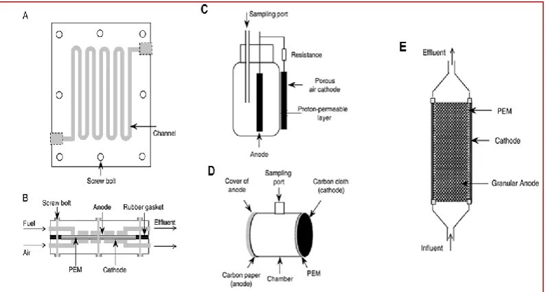
including miniature, cylindrical, up flow, and stacked reactors either dual chambered
(Fig. 2.1) or single chambered (Fig. 2.2) 62. The BBiC team achieved high power densities using small, single-chamber MFC reactors (6.25 mL) which bear
catalyst-free carbon fibre veil electrodes and generating 0.44 W/m3 88. A scale up strategy was evaluated by constructing medium (29.63 mL) and large (500 mL) MFCs and
comparing their performance with that of a 6.25 mL in continuous flow mode. The
small MFC showed a 1.2-fold and 1.9-fold increase in power density, compared to
the medium and the large MFC respectively. This suggests that power output can be
significantly increased during MFC scale-up by utilising a greater number of smaller
21
Figure 2.1. (A) Dual-chamber cylindrical MFC, (B) rectangular, (C) mini-MFC, (D) cylindrical
with up flow configuration. Source: Du et al., 2007.
Figure 2.2. Single-chamber MFCs, (A) top view of a flat plate MFC and (B) side view, (C)
[image:31.595.100.498.443.656.2]22
Figure 2.3. Small-MFCs developed from the Bristol BioEnergy group using in-house 3D
printers.
2.2. Manufacturing materials of small MFCs
To date, most studies have been focusing on the improvement of electrode materials or the reactor’s architecture 62,91–94. The majority of MFC publications, involves MFC casings made out of glass (borosilicate) or Plexiglas
(polymethyl-methacrylate, PMMA or Perspex) 38,62,95,96. However, little is known about the selection of manufacturing materials used to build MFC reactors and only a few
studies report MFC reactors made of various thermo-polymer plastics
(polypropylene, polycarbonate, nanocure and acrylonitrile-butadiene-styrene) 67– 69,71,97–101
where their effect on performance is examined. So far the main reason for
experimenting with plastic polymers is the structural properties of thermoplastics that
allow for a variety of shapes and sizes to be created and their material resistance to
23
This study focuses on the building materials and the reactor architecture of a
novel MFC design (Twist n’ Play) and highlights the fact that when developing a MFC reactor, the construction material should be biocompatible, built for electrical
insulation and minimal oxygen intrusion in the anode chamber so that higher power
outputs can be achieved whilst maintaining functionality with a decreased system
cost.
2.3 Materials and methods
2.3.1 Twist n’ Play MFC-chamber design and fabrication
2.3.1.1 Improvements compared to the EcoBot-III MFC casing
In order to evaluate performance standards of the new design and the materials
involved, a direct comparison with an already proven small-sized MFC 69 of the same internal volume was performed. For this reason three RC25 Nanocure type
EcoBot-III MFCs were used as controls so as to examine whether the architecture of the new
design MFC or the materials involved in the making, can improve the performance. The new ‘Twist n’ Play’ MFC casing was designed using SolidWorks education
Edition 2010 SP 5.0 software (Dassault Systemes, US) and maintained the same
internal reactor volume (6.25 mL) as the fully tested model (EcoBot-III MFC)
developed in 2008 and finalised in 2010 69,88. The improvements on the new MFC design comprised the following features:
a) Same internal volume with smaller external footprint (less building and support
material).
24
c) Minimised exposure of the anode chamber to atmospheric O2.
2.3.1.2 3D printing of the new design
In-house rapid prototyping facilities were employed to fabricate the new MFC (Fig.
2.4) in three different thermoplastics: PC-ISO (medical-grade biocompatible
Polycarbonate; Laserlines, UK), ABS (Acrylonitrile Butadiene Styrene; Laserlines, UK) and RC25 Nanocure (ceramic-filled photo curable resin; envisionTEC GmbH,
Germany). MFCs made out of RC25 nanocure were fabricated with a
Stereolithography 3D printer, whereas PC and ABS MFCs were produced using the
method of Fused Deposition Modelling (FDM Titan/Dimension BST, Laserlines, UK).
Due to the hygroscopic nature of ABS, parts were coated with a layer of
methyl-ethyl-ketone (Sigma-Aldrich, UK) so as to render the units watertight.
The selection of the above materials was based on previous studies 42,69,76,77,88,98,102–104
, in which they were considered to be the most common
thermoplastics used for rapid prototyping and also they could be fabricated in-house.
Figure 2.4. (Left) Twist n’ Play MFC design. (Right) EcoBot-III control MFC design assembly
25
2.4 MFC operation and monitoring
2.4.1 Inoculation and fuel supply
Triplicates of single-chamber air-breathing MFCs were assembled for each
material; both the anode and the cathode electrodes employed catalyst-free carbon
fibre veil sheets 30 g/m2. Sheets of 11 x 14 cm (155 cm2, total surface area) were folded down five times so as to form a 1.8 cm x 2.9 cm x 1.0 cm cuboid. Titanium
wire was used as a current collector, pierced through the carbon veil cuboids. An ion
exchange membrane (CMI-7000, Membranes International Inc., NJ, USA) with a s.a
of 12 cm2 was placed between two silicon rubber gaskets, separating the anode from the cathode. The MFCs were initially inoculated in batch-mode with activated
sewage sludge (Wessex Water, Saltford, UK). Anolyte pH was 7.3 and replenished
every 24 hours with 1 mL of TYE (1% Tryptone, 0.5% Yeast extract, Fisher Scientific, UK) for the first 14 days of the experiment. A 2.7 kΩ resistor was
connected to each MFC during this period for selecting an anodophilic bacterial
consortium; this value was selected in order to best match the Rint. Following 15 days from inoculation, the feedstock was replaced with fresh non-treated human
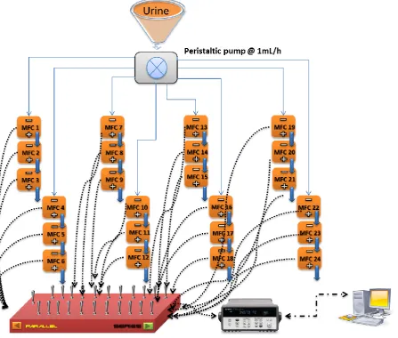
urine and all MFCs were connected to a 24-channel peristaltic pump (Watson
Marlow, UK) for continuous flow, at a rate of 1 mL/h corresponding to a hydraulic
retention time (HRT) of 6.8 h. Samples were received on a daily basis at fixed time of
the day from a healthy individual. Measured pH on fresh urine samples ranged
between 5.5 and 5.8, conductivity was 38 mS/cm average, and the mean chemical
oxygen demand (COD) value from a sampling period of 20 days was 15.5 g/L. All
26
2.4.2 Power curves and data collection
Individual MFC and overall stack (triplet) voltage was recorded using a HP
Agilent multiplex logging unit (34907A, HP). The performance of individual MFCs and triplets was measured by applying a range of 50 resistance values from 30 kΩ
down to 3 Ω every 3 minutes using an automated variable resistor 105. Voltage was measured in V (V), and current (μA) was calculated according to Ohm’s law, I=V/R.
Power in microwatts was subsequently calculated from P = V*I. Power density (PD) was calculated by dividing the absolute power (μW) by the total electrode s.a (α =
155 cm2) and expressed in square-metres (m2). Similarly, the current was divided by the electrode’s α so as to estimate the current density (CD). Recorded data were processed into detailed graphs using GraphPad Prism® version 5.01 software
package (GraphPad, San Diego, California, U.S.A.).
2.4.3 Chemical Oxygen Demand (COD)
For measuring the COD of fresh urine, high range (0-20000 mg/L) potassium
dichromate oxidation method (CAMLAB, UK) was used and COD values were
calculated via colorimetric analysis (Photometer-System MD200, Lovibond). Fresh urine samples (200 μL) were filtered (0.20 μm, Minisart®
) and COD content
measured prior to entering and after exiting the MFCs (24-48 h). Treated urine
samples were initially filtered and then centrifuged at 500 g for 5 minutes.
2.5 Results & Discussion
2.5.1 Performance from Individual new design MFCs
The materials selected in this study were based on 3D printing suitability and use
27
toxicity analyses were not performed however, implicit information could still be
drawn from the MFC performance levels; possible toxic effects from the structural
material, would have detrimentally affected the MFC performance.
Results shown are from 20 days (D20) and 40 days (D40) after inoculation, and
there is clear evidence in terms of improvement in performance due to maturity. The
20-day point was chosen as a point in the transitory period following urine addition
as the fuel, and the 40-day point was chosen as an exemplar of steady state
conditions (Fig. 2.5). Polarisation runs on individual units 20 days after inoculation
(Fig. 2.6) showed that the new design MFCs outperformed the control units in all
three different material cases by a maximum of 74% in terms of power. The control MFCs produced a MPP of 31 μW (2 mW/m2
)at 121 μA (8.1 mA/m2). MFCs made of PC-ISO showed the highest power and current generation amongst the different materials with values of 54 μW (3.6 mW/m2
)and 136 μA (9.1 mA/m2)which was 74% and 12% higher than the control values respectively. The second best performing
MFC material was the RC25 Nanocure, reaching 44 μW (2.6 mW/m2) and 136 μA (9.1 mA/m2) which was 42% higher power and 12% higher current compared to the control. MFCs built with ABS showed also 16% higher power generating 36 μW (2.4
mW/m2) and a 7% increase in current to 130 μA (8.7 mA/m2). To assess performance after a further period of maturity, polarisation experiments were carried
out for individual units 40 days post inoculation, so as to examine establishment of the electro-active biofilm (Fig 2.5). With respect to the maturing between the D20
and D40 period, the control MFCs power improved to 50 μW (3.3 mW/m2) and the current output to 210 μA (14 mA/m2
), which resulted in an increase of 61% and 73%
respectively at the end of the 40 day period. As in the early stages, a similar order in
28
μW (4.4 mW/m2
) and the average current by 160% to 354 μA (23.6 mA/m2); RC25 Nanocure MFCs increased their power output by 29% to 57 μW (3.8 mW/m2
) and the
current output to 329 μA (21.9 mA/m2) an increase of 141%; ABS units produced a power of 50 μW (3.3 mW/m2) and a current of 218 μA (14.5 mA/m2
) which stands for
an increase of 38% and 67% respectively. In terms of performance differences
amongst the examined MFCs compared to the control 40 days after inoculation, the
PC-ISO, the RC25 Nanocure exhibited an increase in power by 32% and 14%
respectively. The current was also higher by 68% (PC-ISO) and 56% (RC25). In the
case of ABS, the power was similar to the control and the current showed only an
increase of 4%. Power sweeps performed in this extended period after the
inoculation presented overshoot peaks in the graph for all the examined materials
and designs. This could suggest that the biofilm had yet to reach the maturity stage
or the resistance value intervals rate were too large and fast for the biofilm to
establish a steady state 106. In both maturing stages all MFCs displayed a similar internal resistance of 2 kΩ, where MPP was achieved.
These results are consistent with findings from a previous study by Ledezma et al.
(2010) that compared ABS, RC25 and PC-ISO as structural materials for a larger
size (25 mL) and different architecture dual-chamber MFC 98. Moreover, the increased outputs from the new Twist n’ Play design when compared to the control EcoBot-III MFC casing built in 2008, suggest that the improvements made on the
design led to a more functional anode chamber, which allowed for better biofilm
29
Figure 2.5. Current generation during 40 days post inoculation as an indication of biofilm maturity
30
Figure 2.6. Power curves from individual units, (A) 20 days post inoculation and (B) 40 days
31
2.5.2 MFCs fluidically connected
2.5.2.1 Parallel electrical connection (n=3)
In this part of the experiments triplets made from the same material were
connected electrically in-parallel, with fluidic connection between the units.
Polarisation results showed a variance in performance based on the output from
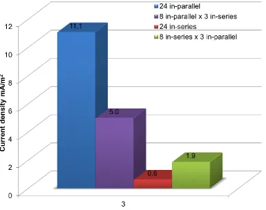
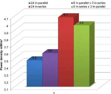
individual MFCs during D40 period. The control MFC triplet reached 129 μW (2.8
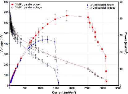
mW/m2) at a current of 0.84 mA, (18.3 mA/m2) (Fig. 2.7). The RC25 Nanocure triplet produced 203 μW (4.4 mW/m2) and a current of 1.3mA (29 mA/m2). ABS triplet generated 152 μW (3.3 mW/m2) and 0.66 mA (14.3 mA/m2). The PC-ISO MFC underperformed compared to the other new design MFCs generating 133 μW (2.9
mW/m2) and 0.64 mA (13.8 mA/m2).
With regard to PD and CD obtained from individual units, the control EcoBot-III design displayed a 15% decrease in PD but a 30% increase in CD. The parallel-connected MFCs made of RC25 Nanocure showed a 16% and 38% increase
respectively. MFCs made of ABS, maintained similar PD and CD levels as the individual MFCs. Increases in CD are to be expected due to the parallel electrical configuration of the MFCs in the triplets. On the contrary, PC-ISO new design
parallel-connected MFCs decreased PD and CD by 34% and 40% respectively. A possible explanation for this reason could be the material’s integrity, as it has the
highest tensile strength of all materials but it possesses a very low endurance to
fracture stress 107 especially after 40 days of operation under hydraulic pressure in the anode chambers. This led to the appearance of ductile tearing zones (Fig. 2.8)
32
casings, that allowed anolyte to leak, therefore allowing oxygen to penetrate into the
anodes, affecting the overall performance.
The in-parallel configuration pushed the system collectively to a more optimum
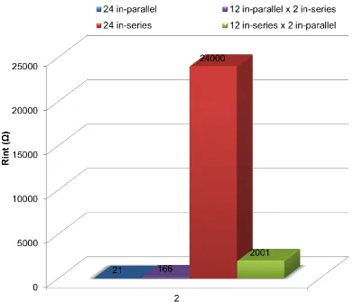
equilibrium which resulted in a decreased internal resistance for all tested MFCs and showed a uniform value of 105 Ω in all cases of 3 MFCs connected in-parallel, which
is equivalent to a 315 Ω for an individual MFC, whereas the internal resistance from
individual units at the beginning of the experiment was 10-times higher. Control MFCs exhibited a 305 Ω internal resistance which stands for a theoretical of 915 Ω in
an individual unit which equals a 2.2-fold decrease compared to their resistance at
the start of the of this study.
Again the newly designed MFC proved to be superior over the control MFC
architecture with the exception of the PC-ISO and an overall comparison between
33
Figure 2.7. Performance of MFCs when connected in-parallel.
Figure 2.8. Characteristics of the (A) ABS with the porous surface, (B) the RC-25
Nanocure with the ceramic integral ruffled surface and (C) the PC-ISO with a cavity
34
2.5.2.2 In-series electrical connection (n=3)
The next stage of the experiment involved triplicates from each material being
connected electrically in-series and each triplet group was connected to a single
feeding channel. Because of its architecture, the new MFC design, allows for tubing
connection between MFC units, thus maintaining hypoxic conditions in the system,
but favours fluidic short-circuiting 88 and could possibly lead to a reduced performance. Conversely, the control MFC was designed for cascade operation. This
involved a vertical orientation of the MFC units placed underneath each other so the
anolyte was gravitationally moved from the first unit to the next one. This set-up
created an air-gap between MFCs that provided hydraulic insulation but allowed for
higher oxygen presence in the system 109.
The ABS-built MFC triplet outperformed the rest and showed an increase of 38%
in power (PD= 3.18 mW/m2) and 54% in current production (CD= 8.21 mA/m2) than the control. The PC-ISO triplets produced 30% more power (PD= 2.83 mW/m2) and 36% more current (CD= 5.93 mA/m2). MFC triplets constructed from RC25 Nanocure, generated 28% more power (PD= 2.74 mW/m2) and 51% higher current (CD= 7.64 mA/m2). The control MFC triplet maintained similar power density levels (PD= 1.96 mW/m2) as in the individual set-up and a showed a 50% reduction of current output (CD= 3.75 mA/m2) also (Fig 2.9.).
2.5.2.2.1 Electrical shunt losses from hydraulic conductivity
Polarisation results on the stacked triplets showed an overall increase in
performance from the Twist n’ Play MFCs compared to the control. Nonetheless, power levels were lower when compared to individual units, which in terms of power
35
by 30% and 14% respectively. Additionally, CD was negatively affected in both materials by 49% in the PC-ISO and 26% in the RC25 Nanocure. The reason behind this diminution is probably due to the fluidical connection within the triplet’s MFCs.
This phenomenon has previously been reported in the literature 88,110 and it has been observed to decrease the performance when stacked MFCs are connected in-series
electrically and feedstock is supplied through a common pathway. As such, the
resistance of the anolyte acts as a load between the cathode of the first and the
anode of the next MFC hence allows for a parasitic current to flow through the
anolyte. However, the power from the control MFC triplet showed little difference.
This can be attributed to the fact that the cascade setup (air-gaps) between MFC
units prevented the feedstock cross-conduction effect (shunt losses) from further
decreasing the performance.
Interestingly, the ABS triplet MFC increased by 18% its power performance and
by 8% the current production even though there was a hydraulic connection
opposing the performance of the other materials under the same operating
conditions. A similar phenomenon was noticed from Ledezma in 2011 111 when stacked MFCs were exposed to different wet conditions so as to investigate shunt
losses in hydraulically stacked MFCs connected electrically in-series. Results from
this study showed that the inconsistent behaviour of the ABS material in wet and dry
conditions were in complete discordance with the other materials operated in the
same manner. Therefore, this antithetic pattern suggested that it was best to avoid
building MFCs from ABS for stacking purposes due to the hydroscopic effects and
36
Finally all new design MFCs showed uniformity in their internal resistance at 1 kΩ,
whereas the control EcoBot-III design produced the maximum power point at 2 kΩ.
Regardless of the increased losses in this setup, new design MFCs showed a lower
internal resistance and better overall output compared to the control MFC setup
where no shunt losses were allowed to occur. Nevertheless, the open surfaces of the
EcoBot-III design MFCs, permeated oxygen to interact with the anolyte and competed with the anaerobic biofilm limiting the biofilm’s electro-genic efficiency.
Figure 2.9. Power curves from MFCs connected electrically in-series.
2.5.3 COD reduction
2.5.3.1 Individual units
The new MFC design was tested in terms of COD reduction, both as a
37
sake of consistency the original COD value of the urine sample used for all the
individual units was 16.8 g/L on the day of the COD measurement. The control units
reduced this value by 29% (11.9 g/L). MFCs made of PC-ISO achieved an average
of 44% COD removal down to 9.4 g/L. RC25 Nanocure units reduced the organic
content by 37% to 10.5 g/L. The mean COD treatment from ABS units resulted in
36% reduction of organic content of the original urine to 10.7 g/L. In terms of the
MFCs running as individual units, the recorded COD removal was proportional to the
order of power performance. It could therefore be suggested that the MFCs with the
best performance characteristics are expected to achieve the highest COD removal
within a number of MFCs displaying various outputs.
2.5.3.2 Stacked MFCs in-parallel (n=3)
COD values were recorded when MFCs of the same material were connected
in-parallel. As it would be expected, COD remediation was increased when more
elements were connected fluidically and configured electrically in-parallel 72. In this case the initial COD content found in the supplied urine sample during the COD
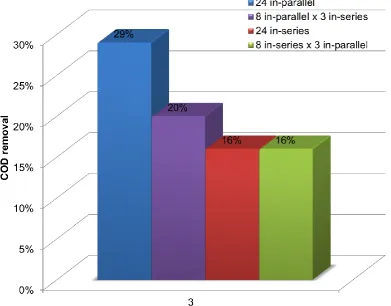
experiment was 19.4 g/L. The control MFC as in the individual test, showed the
lowest range of removal, decreasing the COD value by 38% (7.4 g/L) to a level of 12
g/L. Again the PC-ISO triplet removed a total of 53% (10.3 g/L) which was the
highest amongst the different materials. The COD value from the RC25 Nanocure
stack was decreased by 46% leaving 10.6 g/L of COD in the treated sample. The
ABS stack showed a similar COD treatment with the RC25, reducing the organic
content by 45% down to a value of 10.7 g/L. It is important to point out, that the twist
and play MFC was primarily designed to remain watertight and minimize oxygen
38
not a feature of the control (EcoBot) MFC design. In all material cases besides the
PC-ISO, the stacked MFCs treated the organic content of urine in line with the power
outputs. Nonetheless, the high COD removal value from the PC-ISO was not in accordance with the power output, which could be related with the material’s
structural failure. It is expected that the failure resulted in extensive leakages and
reduction/dilution of the samples, which probably affected the end-treatment product
from the stack. Based on this material bottleneck, more experiments should take
place to confirm the COD removal efficiency.
2.5.3.3 Stacked MFCs in-series (n=3)
Series electrical connections showed a similar ranking –as from individual MFCs-
of reduction by respective MFCs. Even though shunt losses dominated the new
design MFC setup, COD reduction from the PC-ISO (41%), RC25 Nanocure (31%)
and ABS (29%) was higher than the control (25%). In all cases, the reduction was
less than that from individual units suggesting significant energy losses because of
the series connection. The new design MFCs were probably affected from the
cross-conduction effect 110,112 and the control MFC was affected by the exposure to atmospheric oxygen anode.
2.6 Conclusions
In principle, a MFC’s performance is affected by many variables, and behaviour
of one factor may be directly influenced by other parts of the MFC. A common
feature in the process that affects electricity production and COD removal is largely
dependent on the materials used. It could be argued that the materials and
39
types and structures. Several challenges need to be resolved, including high areal
resistivity, high oxygen leakage and non-compatibility with micro-fabrication.
This experimental study showed how three versions of a novel MFC reactor can
greatly affect their overall performance of MFCs under fluidic and electrical
scenarios. The new design showed an overall increased performance compared to
the control MFC reactor and depending on the electrical and the fluidic connection
the RC25 Nanocure and the ABS seemed to perform better in terms of power and
COD treatment of up to 15% increase whilst retaining better power and COD values
than the control.
Even for rapid prototype materials, which are expected to be of a finite lifetime,
RC25 Nanocure proved to be the most robust. These results demonstrate that the
RP technology is a useful tool for examining various materials as structural elements
for MFC reactors and the combination of the best performing plastic polymers, could
possibly introduce a hybrid material that will advance miniaturisation of MFCs and
41
Chapter 3
Parts of the following results presented in this chapter have been published in:
Papaharalabos, G., Greenman, J., Melhuish, C., Santoro, C., Cristiani, P., Li, B., &
Ieropoulos, I. (2013). Increased power output from micro porous layer (MPL) cathode
microbial fuel cells (MFC). International Journal of Hydrogen Energy, 38(26), 11552–
11558.
3. Power increase in MFCs
The second experimental chapter utilises a low-cost catalyst-free electrode as a
cathode in small-size MFCs so as to improve reaction kinetics and by extension, the
power output. It also demonstrates that the increase in power is sufficient enough for
two small-MFCs to run for the time an off-the-shelf wristwatch.
3.1. Focus on cathode optimisation
A different approach to miniaturisation for improving power in open-to-air cathode
MFCs is the efficient utilisation of oxygen on the cathode - higher ORR - by using
high s.a materials with effective gas diffusion.
Oxygen is the most abundant and naturally occurring electron acceptor with a
high redox potential (0.82 V). It has been suggested that the power output of a MFC
can be greatly improved by increasing the surface area of the cathode electrode 40,41,113
. Greater surface area means larger number of active sites for the ORR, and
the micro porous layer coating has been suggested as an efficient and inexpensive
way of achieving higher active s.a 114. A micro porous layer (MPL) is a mixture of carbon black nanoparticle powder and polytetrafluoroethylene (PTFE). Carbon black
particles form a high surface area of carbon active sites, along with an extensive
42
ability to (i) facilitate oxygen diffusion through the inner structure and all the way to
the ion exchange membrane (IEM) surface, (ii) produce water from the reaction with
the incoming protons through the IEM, and (iii) avoid flooding due to the PTFE.
The present study builds on the previous work by Santoro et al. 114 and aims to compare the performance of small-scale MFCs incorporating MPL cathode
electrodes, with control carbon veil electrode 88. The specific aims of this study were to test (i) individual MFCs with the new electrode material, (ii) stacks of 3 MFCs in a
series/parallel configuration employing the MPL electrodes and (iii) the effect that the
MPL electrodes had on the hydration regime of the open-to-air cathodes. As a
practical demonstration of the performance improvement from MPL, two small-scale
MFCs were used to power a Texas Instruments Chronos digital wristwatch.
3.2. Materials and Methods
3.2.1. Small scale 6.25mL MFCs
Six open-to-air cathode MFCs, made from RC25 Nanocure resin in a 3D
fabrication process, were used in these experiments. The internal volume of the anode compartment was 6.25mL, and the anode’s electrode projected s.a was 6cm2
,
as previously described42. All MFCs had an IEM (VWR, Leicestershire, U.K.) that was held between two rubber gaskets. For the duration of experiments, open-to-air
cathodes were manually hydrated every 24 hours.
3.2.2. Electrode materials
A catalyst free carbon fibre veil (Fig. 3.1) with a carbon loading of 20g/m2 (PRF Composites, Dorset, U.K) was used as the anode electrode for all 6 MFCs,