http://www.scirp.org/journal/ijcns ISSN Online: 1913-3723
ISSN Print: 1913-3715
Quantum Secret Broadcast for Wireless
Quantum Networks
Tao Shang, Gang Du, Jianwei Liu
School of Electronic and Information Engineering, Beihang University, Beijing, China
Abstract
In wireless quantum networks, nodes communicate by means of pre-distri- bution for entangled pairs and relay path establishment for quantum telepor-tation. However, simple point-to-point communication seriously restricts the efficiency of quantum communication. Inspired by sharing idea of quantum secret sharing (QSS), which is based on three collaborative nodes with pre-shared GHZ (Greenberger-Horne-Zeilinger) states, we propose a quan-tum secret broadcast scheme to improve network performance. In a cluster network cored on three parties of QSS, three cluster heads with pre-shared GHZ states are senders, while cluster members are receivers. One cluster head encodes secret messages on auxiliary particles by performing certain opera-tions on them with GHZ particles, then three cluster heads measure their own particles and broadcast measurement results honestly. Based on the specific correlation of measurement results and secret messages, all receivers can re-cover the secret messages. Furthermore, to prevent eavesdropping, cluster heads can update an encoding key periodically. Analysis shows the proposed scheme is more efficient than previous schemes in wireless quantum net-works, especially when the number of receivers is larger. Besides, in the pro-posed scheme, attacks on quantum channel based on GHZ state can be de-tected, and eavesdroppers cannot recover messages correctly for lack of suita-ble decoding key.
Keywords
Quantum Secret Sharing, Quantum Secret Broadcast, Cluster Network
1. Introduction
Since the first quantum key distribution (QKD) protocol BB84 [1] was proposed, quantum communication has attracted much attention in the filed of infor- mation security. In order to meet the demand of adaptive quantum communi-
How to cite this paper: Shang, T., Du, G. and Liu, J.W. (2017) Quantum Secret Broadcast for Wireless Quantum Networks. Int. J. Communications, Network and System Sciences, 10, 7-18.
https://doi.org/10.4236/ijcns.2017.108B002
cation, quantum communication in the area of wireless network has been exploited. Cheng et al. [2] made the first attempt in wireless quantum networks (WQN) and proposed a quantum routing mechanism, which allows teleporting a quantum state from a node to another node. Li et al. [3] designed a framework for distributed wireless quantum networks. In 2013, Cao et al. [4] applied a cluster mesh structure and addressed the problems of EPR resources and quantum channel establishment. The above researches gradually enhance the feasibility of wireless quantum networks. However, there are still a problem in WQN, that is inefficient, i.e., a source node will consume relay nodes’ resources , and it can only send a message to one destination node once instead of several nodes.
Quantum secret sharing (QSS) is an important branch of quantum crypto- graphy, which is a generalization of the classical secret sharing into the quantum domain. Since the first QSS protocol was presented by Hillery et al. [5], various QSS schemes have been proposed [6] [7] [8] [9]. In a typical three-party QSS scheme [8], a sender, Alice, splits a secret message into two shares and dis- tributes the shares to two receivers, Bob and Charlie, so that none of them can recover the secret from their own shares. Only if Bob and Charlie publish their own measurement results honestly, can they read out the secret message cor- rectly.
Inspired by the feature of QSS that more than one party can receive secret message each time, we introduce the idea of QSS into a wireless quantum network, and propose a quantum secret broadcast scheme to solve the troubling efficiency problem. In a cluster network cored on three parties of QSS, three cluster heads, Alice, Bob, and Charlie will collaborate honestly to broadcast messages to cluster members by using pre-shared GHZ states. The communi- cation mode can be whole-network broadcast or intra-cluster broadcast. Furthermore, to prevent illegal eavesdropping, three cluster heads will perio- dically update a encoding key Y. Consequently, illegal nodes cannot read out the message correctly for lack of suitable decoding key.
2. Related Works
2.1. Wireless Quantum Networks
Wireless quantum networks (WQN) has been studied by many groups [2] [3] [4] [10] to exploit quantum communication into the area of wireless network. The basic method of communication between nodes in WQN is quantum tele- portation. Figure 1 shows an example of wireless quantum network, where dotted line represents quantum channel based on EPR pairs. We assume node A
is a source node and node E is a destination node. A possible routing path is A→ → →C D E, which means the relay node C and D will also consume their EPR pairs and classical bits to assist this communication.
Figure 1. Wireless quantum network.
relay path establishment.
2.2. Three-Party QSS
In 2009, Liu et al. [8] proposed a three-party QSS scheme with pre-shared GHZ states, which uses an auxiliary EPR pair to encode two secret message bits.
By convention, the sender is denoted as Alice (A), and the receivers is denoted as Bob (B) and Charlie (C). First, they share three-particle GHZ states, each of which is:
(
)
1
000 111
2 ABC
Φ = + (1)
After eavesdropping check to ensure the security of quantum channel (GHZ states), Alice prepares an EPR pair in the state:
(
)
1 2 1
00 11
2 a a
φ+ = + (2)
Four unitary operators are defined as: U00= 0 0 + 1 1 ,
01 1 0 0 1
U = + , U10= 0 1− 1 0 , U11= 0 0 −1 1. The system state after encoding can be expressed as:
1 2 X 1 2
a a ABC U φ a a ABC
+
Φ = ⊗ Φ (3)
where UX is one of four operations U00, U01, U10, U11, which encodes a
two-bit message “00”, “01”, “10”, and “11”, respectively.
Next, Alice applies a controlled-NOT (CNOT) gate on both particle A and particle a1, here a1 is the controller and A is the target. Then she sends the
particle a1 and a2 through the Hadamard (H) gate, respectively.
Then Alice applies a Bell-state measurement on both particles a1 and a2,
Bob and Charlie measure the particle B and C with diagonal basis
{ , }
X
different encoding operation UX Alice performs. Thus Bob and Charlie can
consider three parties’ measurement results and further recover secret messages.
3. The Proposed Scheme
In Liu’s QSS scheme [8], the correlation between the measurement results and secret message play a important role in decoding. Assume that other nodes are also aware of the correlation, they can also recover the secret messages.
The main idea of our scheme is that in a cluster network cored on three parties of QSS, Alice (A), Bob (B), and Charlie (C) are cluster heads. In each communication period, one cluster head plays the role of a message sender, other two cluster heads are assistants to help sender broadcast messages. Moreover, we design two types of communication modes, namely whole- network broadcast and intra-cluster broadcast, to meet different requirement of a sender.
The quantum secret broadcast scheme is described as follows:
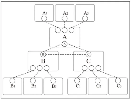
Step 0: Initializing
Figure 2 shows initializing phase of the scheme. We apply a cluster structure for network, three cluster heads A, B, and C, own three-party GHZ states, each GHZ state is:
(
)
1
000 111
2 ABC
Φ = + (4)
where A, B and C indicate the particle held by A, B, C respectively. Each cluster head has its own cluster members, we denote A’s members as
1 2 3
[A A A, , ,...], B’s and C’s members as [B B B1, 2, 3,...] and [C C C1, 2, 3,...],
respectively. Moreover, each cluster head shares EPR pairs with its own cluster members, respectively.
[image:4.595.238.511.511.717.2]Before communication, quantum channel of GHZ states should be checked for potential attacks, the GHZ among A, B and C can be rewritten as:
(
)
12 ABC
Φ = + + + + + − − + − + − + − − + (5)
where 2
(
0 1)
2+ = + , 2
(
0 1)
2
− = − . According to Equation (7), if A
performs measurement under basis σx on her particle and the result is + or
− , the measurement results of B and C should be + + , − − or + − , − + . For a secure channel without disturbing, three parties’ measurement results must be correlated as Equation (7). By using this method, A can choose a subset of particles to detect if there exists a attack. If the error rate of measurement results is under the threshold, the channel is secure and the scheme continues, otherwise, if the channel is insecure, the scheme is ter- minated.
Step 1: Encoding key updating. When each communication period begins,
three cluster heads generate a two-bit “encoding key” Y by turns, and then transmit it to other two cluster heads by quantum teleportation.
Assume that it is A’s turn to produce the “encoding key” Y, which is one of the four possible encoding key “00”, “01”, “10”, and “11”. Then she prepares two qubits for B and C, respectively, in which the state 1
(
0 1)
2
+ = + means
“1”, and the state 1
(
0 1)
2− = − means “0”. After that, A sends two qubits
represented Y to B and C by controlled quantum teleportation [11], res- pectively.
When B, C both receive the encoding key Y, three cluster heads transmit the key to their own cluster members by quantum teleportation based on shared EPR pairs.
After that, the whole network knows the latest encoding key. So the encoding key updating phase is completed.
Step 2: Communication mode selecting. To meet different requirement of
cluster heads, the communication mode can be selected to whole-network broadcast or intra-cluster broadcast.
If a cluster head needs to broadcast messages to the whole network, it will announce an application in this step. Then three cluster heads discuss to select one appropriate cluster heads to be the sender of whole-network broadcast. Otherwise, the communication switches into the mode of intra-cluster broadcast if no cluster heads announce an application.
1) Whole-network broadcast
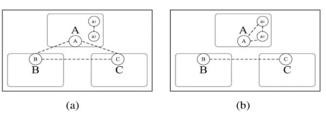
Step 3: Message encoding. Assume that cluster head A is chosen to be the
sender. For each shared GHZ state, she prepares an auxiliary EPR state as follows:
(
)
1 2 1 2
1
00 11
2 a a
a a
φ+ = + (6)
Figure 3. System state of whole-network broadcast.
state.
We define four unitary operators:
00 01
10 11
1 0 0 1
,
0 1 1 0
0 1 1 0
,
1 0 0 1
U U U U = = = = − − (7)
Step (3.1) A encodes message on EPR state with two operators UX and UY,
the system state becomes:
X Y ABC
U U
φ
+Φ = ⊗ Φ (8)
where X is the two bits message and Y is the encoding key.
For convenience, we assume the encoding key Y is “00”. After encoding with two operators, we obtain:
(
)
1 2
1 2
00 00 00
1
00000 11000 00111 11111 2
ABC a a
a a ABC
U U φ+
Φ = ⊗ Φ
= + + + (9)
(
)
1 2
1 2
01 01 00
1
01000 10000 01111 10111 2
ABC a a
a a ABC
U U φ+
Φ = ⊗ Φ
= + + + (10)
(
)
1 2
1 2
10 10 00
1
01000 10000 01111 10111 2
ABC a a
a a ABC
U U φ+
Φ = ⊗ Φ
= − + − (11)
(
)
1 2
1 2
11 11 00
1
00000 11000 00111 11111 2
ABC a a
a a ABC
U U φ+
Φ = ⊗ Φ
= − + − (12)
Step (3.2) A applies a CNOT gate on both particles a1 and A, here a1 is
the controller and A is the target.
Step (3.3) A performs a Hadamard gate on a1 and a2, respectively. After
that, the system state can be written as:
1 2
1 2
00
1 1 1
[ ( 00 11 ) ( )
2 2 2
1 1
( 01 10 ) ( ) ]
2 2
a a A BC
a a A BC
'
Φ = + + ⊗ + + + − −
1 2
1 2
01
1 1 1
[ ( 00 11 ) ( )
2 2 2
1 1
( 01 10 ) ( ) ]
2 2
a a A BC
a a A BC
'
Φ = − + ⊗ + + + − −
− + − ⊗ + − + − + (14)
1 2
1 2
10
1 1 1
[ ( 00 11 ) ( )
2 2 2
1 1
( 01 10 ) ( ) ]
2 2
a a A BC
a a A BC
'
Φ = − − ⊗ + − + − +
− − + ⊗ + + + − − (15)
1 2
1 2
11
1 1 1
[ ( 00 11 ) ( )
2 2 2
1 1
( 01 10 ) ( ) ]
2 2
a a A BC
a a A BC
'
Φ = + − ⊗ + − + − +
+ + + ⊗ + + + − − (16)
System state after encoding is as shown in Figure 3(b), where the original entangled GHZ state Φ ABC is destroyed, while particles a1, a2, A form a
new three-party entangled state, B and C form a two-party entangled state.
Step4: Measurement result broadcasting. Sender A performs Bell-state mea-
surement on both particles a1 and a2, B and C measures their own particle
B and C with basis σx, respectively. Then, they broadcast own mea- surement results.
Step 5: Message decoding.
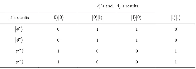
Step (5.1) All the cluster members consider three cluster heads’ measurement
results and can read out A’s messages M by referring to the correlation of measurement results and messages, which can be inferred from Equations (13)-(16) and listed in Table 1.
Step (5.2) As M is a message encoded with the encoding key Y, so re-
ceivers need to decode the message with encoding key Y to obtain the original message Mo:
o
M =M⊕Y (17)
Let us take an example to illustrate how the mode of whole-network broadcast works. At first, we assume that the encoding key Y is “10”, and it is informed to all nodes in Step 1 of Encoding key updating, and A is chosen to be the sender in the mode of whole-network broadcast. After encoding, A’s measurement results are
φ ψ φ
+ − − ..., B’s results are + − + ..., and C’s results are...
[image:7.595.255.539.75.247.2]− − + , all nodes consider three cluster heads’ results and refer to Table 1
Table 1. Correlation of measurement results and messages in whole-network mode.
B’s and C’s results
A’s results + + + − − + − −
φ+
00 11 11 00
φ−
01 10 10 01
ψ+
11 00 00 11
to read out massages M as “11”, “10”, “01”, …, then receivers XOR (exclusive OR) the encoding key Y =10 and M to recover original messages MO as
“01”, “00”, “11”, ….
2) Intra-cluster broadcast
Assume that no cluster heads announce an application, the communication will switch into the mode of intra-cluster broadcast, in which three cluster heads can send messages to their own cluster members. We take A as an example to illustrate this mode.
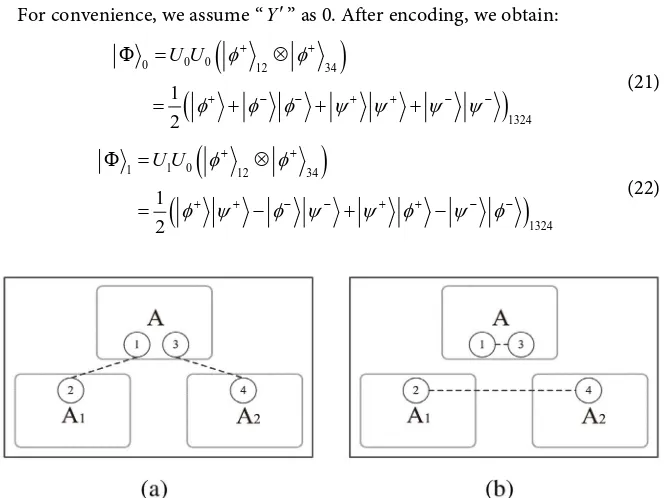
Step 3: Message encoding. Similarly, based on the idea of QSS, A randomly selects two cluster members (denote as A1 and A2) to be assistant. The system
state of three parties is:
1234 φ 12 φ 34
+ +
Φ = ⊗ (18) As is shown in Figure 4(a), A holds particle 1 and 3, while A1 and A2 hold
the particle 2 and 4, respectively. Particle 1 and 2 form an entangled state, 3 and 4 form an entangled state.
We define two unitary operators for encoding:
0 1
1 0 0 1
,
0 1 1 0
U = U =
(19) A encodes one bit message on particle 1 with two operators UZ and UY′,
system state will be :
( )
Z Y
U U ′
φ
+φ
+Φ = ⊗ (20) where Z is the one bit message, Y′ is a number by XORing the first digit and the second digit of the encoding key Y. For example, assume the encoding key
Y is “11”, Y′ should be Y′ = ⊕ =1 1 0.
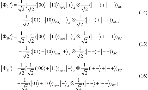
For convenience, we assume “Y′” as 0. After encoding, we obtain:
(
)
(
)
0 0
0 12 34
1324
1 2
U U φ φ
φ φ φ ψ ψ ψ ψ
+ +
+ − − + + − −
Φ = ⊗
= + + + (21)
(
)
(
)
1 0
1 12 34
1324
1 2
U U φ φ
φ ψ φ ψ ψ φ ψ φ
+ +
+ + − − + + − −
Φ = ⊗
[image:8.595.208.542.465.714.2]= − + − (22)
From Equations (21)-(22), system state is changed as shown in Figure 4(b), where the two original entangled pairs are all destroyed, and particle 1 and 3 form a new entangled state, 2 and 4 form a new entangled state.
Step 4: Measurement result Broadcasting. A performs a Bell-state mea-
surement on both particles 1 and 3, A1 and A2 measures the particle 2 and 4
with basis σZ. Then, they all broadcast the measurement results. Step 5: Message decoding.
Step (5.1) A’s cluster members consider three parties’ results and read out
message M by referring to the correlation of measurement results and messages, which is inferred from Equations (21)-(22) and listed in Table 2.
Step (5.2) M is a message encoded with Y′, so receivers need to decode the message with Y′ to obtain the original message Mo:
o
M =M⊕Y′ (23) We take an example of A cluster to illustrate how intra-cluster mode works. Assume that the encoding key Y is still “10”, so Y′ = ⊕ =0 1 1. A’s results are
...
φ φ ψ
+ − + ,1
A ‘s and A2‘s results are 0 1 0 ... and 0 1 1 ...,
respectively. A’s cluster members consider three parties’ results and refer to Table 2 to read out messages M “0”, “0”, “0”, …, then they XOR the M and
Y′ to recover original messages MO as “1”, “1”, “1”, ….
4. Scheme Analysis
4.1. Network
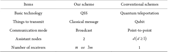
Our scheme aims to achieve message broadcast in WQN, which attempts to extend communication mode and improve network performance. Different from conventional schemes based on quantum teleportation [2] [3] [4] [10], we apply the method of QSS instead of teleportation.
[image:9.595.208.539.620.737.2]For the reason of applying QSS, our scheme has differences with conventional schemes which are based on quantum teleportation in many aspects. Our scheme transmits classical messages by broadcast, while previous ones transmit quantum state by teleportation. Our scheme makes a attempt to achieve message broadcast, the number of receivers can be m or 3m under different com- munication mode, where m is the number of cluster members. Each sender needs two assistants in our scheme, while conventional schemes also needs
Table 2. Correlation of measurement results and messages in intra-cluster mode.
1
A‘s and A2‘s results
A’s results 0 0 0 1 1 0 1 1
φ+ 0 1 1 0
φ− 0 1 1 0
ψ+
1 0 0 1
nodes as assistants to build a routing path from source to destination, the farther distance between source and destination is, the more assistant nodes are needed. we denote d as the number of assistant nodes.
Table 3 gives a summary of comparison between our scheme and con- ventional schemes.
4.2. Efficiency
The efficiency in our quantum communication protocol can be defined as:
u
t
m n
q
η= (24)
where mu is the number of transmitted qubits, qt is the number of consumed
qubits, n is the number of message receivers.
We make a comparison between our scheme and Cao’s scheme [4], for the latter is a typical research of previous schemes and it also uses a cluster structure for WQN.
Consider a situation that a cluster head sends messages to his and other cluster heads’ members. In our scheme, mu=1 for 2 classical bits are eq- uivalent to 1 qubit, qt=5, n=3m (in the mode of whole-network broadcast),
m is the number of one cluster members. In Cao’s scheme, mu=1, n=1, ( 1)
t
q =d d≥ , for the distance between sender and receiver is at least 1. Table 4 makes a comparison between our scheme and Yang’s scheme.
[image:10.595.206.541.469.572.2]We can see from Table 4 that the performance of our scheme is better than Yang’s scheme, especially when the number of receivers n is larger and distance d is farther.
Table 3. Comprehensive comparison.
Items Our scheme Conventional schemes
Basic technology QSS Quantum teleportation
Things to transmit Classical message Qubit
Communication mode Broadcast Point-to-point
Assistant nodes 2 d d
(
≥1)
[image:10.595.208.542.602.736.2]Number of receivers m or 3m 1
Table 4. Efficiency comparison.
Scheme Our scheme Cao’s scheme
u
m 1 1
t
q 5 d( 1)≥
n 3m 1
η for m = 5, d = 2 3 1
2
η for m = 10, d = 3 6 1
4.3. Security
In the proposed scheme, no qubits carrying messages are transmitted directly, so quantum channel only exists in the GHZ states. If an eavesdropper Eve cannot escape from the security check at the phase of Step 0: Initializing, our scheme is secure. The security check method of our scheme is the same as QSS schemes in [7] [8], which assumes Eve’s attack E
∧
performs on Hilbert space HABC⊗HE,
then the whole quantum system can be written as:
1 000 1 001
1 010 1 011
2 100 2 101
2 110 2 111
1
[( 0 ( 00 01
2
10 11 )
( 1 ( 11 10
01 00 )]
α ε β ε γ ε δ ε
δ ε γ ε β ε α ε
Ω = +
+ +
+ +
+ +
(25)
The error rate involved in Eve is 2 2
1 2
1 1
λ
= −α
= −δ
, so Eve can be easilydetected during the process of security check.
Considering that receivers read out messages according to the three cluster head’s measurement results, another secure problem is that if an eavesdropper also knows the correlation between messages and measurement results, it can obtain messages. To solve this problem, our scheme generates an encoding key Y periodically to add an extra encoding operation. Just like one-time pad, the encoding key plays a role of periodically updating a key to encode and decode messages, and it will be informed to all network before communication. If an eavesdropper is not in the cluster of three heads, it will not obtain the latest key, so it can only randomly select one of “00”, “01”, “10”, “11” as the key to recover messages.
In the whole-network mode, by randomly selecting a key, an eavesdropper will recover a message with the error rate 75%, while in the intra-cluster mode, the error rate is 50%. So our scheme uses security check for quantum channel and key updating for secret messages to ensure security.
5. Conclusion
Acknowledgements
This project was supported by the National Natural Science Foundation of Chi-na (No. 61571024) and the NatioChi-nal Key Research and Development Program of China (No. 2016YFC1000307) for valuable helps.
References
[1] Bennett, C.H. and Brassard, G. (1984) Quantum Cryptography: Public-Key Distri-bution and Tossing. Proceedings of IEEE International Conference on Computers, Systems and Signal Processing, Bangalore, India, IEEE Press, 175-179.
[2] Cheng, S.T., Wang, C.Y. and Tao, M.H. (2005) Quantum Communication for Wire-less Wide-Area Networks. IEEE Journal on Selected Areas in Communications, 23, 1424-1432. https://doi.org/10.1109/JSAC.2005.851157
[3] Li, J.S. and Yang, C.F. (2009) Quantum Communication in Distributed Wireless Sensor Networks. IEEE 6th International Conference, Macau, 12-15 Oct. 2009, 1024-1029. https://doi.org/10.1109/MOBHOC.2009.5337016
[4] Cao, Y., Yu, X.Y. and Cai, Y.X. (2013) Wireless Quantum Communication Net-works with Mesh Structure. IEEE 3rd International Conference on Information Science and Technology, Yangzhou, 23-25 March 2013, 1485-1489.
https://doi.org/10.1109/ICIST.2013.6747818
[5] Hillery, M., Buzek, V. and Berthiaume, A. (1999) Quantum Secret Sharing. Physical Review A, 59, 1829-1834. https://doi.org/10.1103/PhysRevA.59.1829
[6] Deng, F.G., Zhou, H.Y. and Long, G.L. (2005) Bidirectional Quantum Secret Sharing and Secret Splitting with Polarized Single Photons. Physics Letters A, 337, 329-334. https://doi.org/10.1016/j.physleta.2005.02.001
[7] Wang, J., Zhang, Q. and Tang, C.J. (2007) Multiparty Quantum Secret Sharing of Secure Direct Communication Using Teleportation. Communications in Theoretical Physics, 47, 454-458. https://doi.org/10.1088/0253-6102/47/3/015
[8] Liu, Y. and Xu, C. (2009) Three-Party Quantum Secret Sharing Based on Secret Di-rect Communication. International Forum on Information Technology and Appli-cations, 1, 126-130.
[9] Hwang, T., Hwang, C.C. and Li, C.M. (2011) Multiparty Quantum Secret Sharing Based on GHZ States. Physica Scripta, 83, 045004.
https://doi.org/10.1088/0031-8949/83/04/045004
[10]Nguyen, T.M.T., Sfaxi, M.A. and Ghernaouti-Helie, S. (2006) Integration of Quan-tum Cryptography in 802.11 Networks. Proc. 1st Int. Conf. on Availability, Reliabil-ity and SecurReliabil-ity, Vienna, 20-22 April 2006, 116-123.
https://doi.org/10.1109/ARES.2006.75
[11]Zhou, J.D., How, G. and Wu, S.J. (2007) Controlled Teleportation of an Arbitrary Multi-Qudit State in a General Form with d-Dimensional Greenberger-Horne-Zei- linger States. Chinese Physics Letters, 24, 1151-1153.
https://doi.org/10.1088/0256-307X/24/5/007
Submit or recommend next manuscript to SCIRP and we will provide best service for you:
Accepting pre-submission inquiries through Email, Facebook, LinkedIn, Twitter, etc. A wide selection of journals (inclusive of 9 subjects, more than 200 journals)
Providing 24-hour high-quality service User-friendly online submission system Fair and swift peer-review system
Efficient typesetting and proofreading procedure
Display of the result of downloads and visits, as well as the number of cited articles Maximum dissemination of your research work
Submit your manuscript at: http://papersubmission.scirp.org/