Operator Splitting Method for Coupled Problems:
Transport and Maxwell Equations
Jürgen Geiser
Department of Mathematics, Humboldt-Universität zu Berlin, Unter den Linden, Berlin, Germany E-mail: [email protected]
Received March 31, 2011; revised April 13, 2011; accepted May 2, 2011
Abstract
In this article a new approach is considered for implementing operator splitting methods for transport prob-lems, influenced by electric fields. Our motivation came to model PE-CVD (plasma-enhanced chemical va-por deposition) processes, means the flow of species to a gas-phase, which are influenced by an electric field. Such a field we can model by wave equations. The main contributions are to improve the standard discretiza-tion schemes of each part of the coupling equadiscretiza-tion. So we discuss an improvement with implicit Runge- Kutta methods instead of the Yee’s algorithm. Further we balance the solver method between the Maxwell and Transport equation.
Keywords: Operator Splitting Method, Initial Value Problems, Iterative Solver Method, Stability Analysis, Beam Propagation Methods, Transport and Maxwell Equations
1. Introduction
We motivate our study by simulating thin film deposition processes that can be realized by PE-CVD (plasma en-hanced chemical vapor deposition) processes, see [1,2]. For the deposition process, the influence of the electric fields to the transported gases in a plasma reactor is very important, see [3]. Therefore we deal with a simplified model of a coupled transport and Maxwell equations. While the transport equations modeled the transport of gaseous species and the Maxwell equation the influence of the underlying flow field.
We deal with the following equations
222 2
= ,
,
t x z y
u u
u v E x y v D
x y
u x
u D
y
(1)
, ,0
= 0
, ,u x y t u x y (2)
,
= , , , 0,
x z
H x y E
,x y t T
t y
(3)
,
= , , , 0,
y z
H x y E
, 1
= ,
, , 0, ,
y
z x
source H
E x y H
J
t x y
x y t T
(5)
where u is the concentration of the gaseous species, Ez is the electric field and H Hx, y is the corresponding magnetic field in two dimensions. Further v=
vx,vy
t is the influenced velocity of the transport equation.We concentrate on the numerical modeling and simu-lation of electrical fields, which are coupled with trans-port equations.
Several methods exist to solve electric field and are of interest.
One method for a stationary case of the electric field is a propagation method (BPM). This is a powerful tool to analyze linear and nonlinear light propagation in axially varying waveguides like directional couplers, tapered waveguides, S-shaped bent waveguides, and optical fi-bers [4-7]. The method has its origin in the field of propagation of electromagnetic beams in atmosphere, where the multi-physics modeling was done on the as-sumption that “the continuous gain medium may be ap-proximated by a series of gain sheets with free propaga-tion between the sheets” [8,9]. As it will be shown later on, this method is in fact a Strang-Marchuk operator splitting method [10,11]. Here we first describe the BPM [12]. We introduce the iterative splitting idea to couple
,x y t T
t x
164 J. GEISER Maxwell and Transport equations. Further a splitting analysis is presented. Numerical experiments are pre-sented with respect to decoupled and coupled differential equations.
The paper is organized as follows. The discretization methods are described in Section 2. In Section 3, the applied operator splitting methods are presented. The error analysis of the coupled methods is studied in Sec-tion 4. The experiments of the new discretizaSec-tion meth-ods and splitting methmeth-ods are performed in Section 5. At the end of this paper we introduce future works.
2. Discretization Method of the Maxwell
Equation
In the following we discuss the discretization methods for the Maxwell equation.
2.1. FDTD Method: Yee’s Scheme
Yee’s scheme is the standard finite difference time-do- main (FDTD) discretization of the following time de-pendent Maxwell curl equations
0 =
H ,
E r
t
(6)
0 =
E
, H r
t
(7)
where E=
E E Ex, y, z
x y t, ,
is the electric field, H=
Hx,Hy,Hz
x y t, ,
is the magnetic field, r =
x y,= 1
r
is the relative permittivity (given data), (non- magnetic material) is the magnetic permeability. Here
0
, 0 are constants. It can be shown that if the
diver-gence free conditions
rE
= 0 and
H = 0are satisfied at , then they are satisfied for all time. This is the case for our setting. Therefore it is enough to consider only the above curl equation. Rewriting them component-wise, we get in our case
= 0
t
0 =
y
x z E
H E
t y
z (8)
0 =
y x z
H E E
t z
x (9)
0 =
y x
z r
H H
E
t x
y (10)
Let x, y are spatial discretizations, and t is a
time step. We use the following notation
, =
, ,
n .
F i j F i x j y n t (11)
Let represents a spatial coordinate such as x, . The goal of Yee’s scheme is to compute the
approxima-tions for the various components
y
E of E and H
of H at the following spatial locations and temporal
instants:
:
:
= :
spatial coordinate inte
other spatial coordina teg time integer
half te in
= :
nteger ger er
E
(12)
:
:
spatial coordinate i
H other spatial coordinat alf er
time half integer
e h integ
(13)
Thus the distributions/grid of various components are staggered in space and in time. This is one of the two unique characteristics of the Yee’s scheme. The second unique characteristic is that the various spatial deriva-tives in Equations (8) - (10) are computed across the one spatial cell, i.e. the difference center for the central dif-ference approximation of the spatial derivative is the mid point of one cell length in the corresponding direction of the derivative. Thus the Yee’s scheme approximates Equations (8) - (10) at the following points:
Equation (8) i x , j1 2 y,n t (14)
Equation (9) i1 2 x,jy n t, (15)
Equation (10) i x j y n , , 1 2 t (16)
Such a staggered uncollocated arrangement gives the Yee’s scheme several nice numerical and physical prop-erties, see [13]. Then we get finite-difference approxima-tions as:
z
,1 2
1 2
0
1 ,
2
1 1
= , , 1 ,
2
x z
H i j
t xn
n
n n
H i j E i j i j
y
E
(17)
z
,1 2
1 2
0
1 , 2
1 1
= , 1 ,
2
y z
H i j
t ny
n
,
n n
H i j E i j i j
x
E
(18)
1
1 1
2
, ,
2
0
1 1
2 2
0
,
= ,
1 1 1
2 2
1 , 1 ,
2 2
n n
y y
r
n n
x x
r E i j E i j
t n
z
n z
1 .
H i j H i j
x
t
H i j H i j
y
(19)
In Equation (19) the relative permittivity r is com-puted at the corresponding difference center as given by Equation (16). At the interface between two media, r is approximated by the average value.
Conditions for the Yee’s algorithm:
● The CFL stability condition for the Yee’s FDTD method is
21 1 1
t
c x y 2
(20)
where c is the speed of light in vacuum, see [13].
● To restrict the unbounded domain to finite domain, one uses absorbing boundary condition like the perfectly matched layers, see [14,15].
Remark 1. Often for more accurate problems a Yee’s algorithm which is second order in time and second or-der in space is often to low. For higher order methods in time and space can be constructed but are often to deli-cate and expensive to implement, see [16,17]. We pro-pose to improve with higher order implicit Runge-Kutta methods with an idea to sparse matrices schemes, which saves additional memory.
2.2. Improved Time Discretization Methods for Maxwell Equation
Based on the problem of reconstructing a higher order Yee’s algorithm, we deal with separate improvement of the discretization schemes.
While the spatial discretization of the Yee’s algorithm is a second order difference scheme, the time discretiza-tion is also only a second order scheme.
Here we see the deficits of only improving the spatial scheme with higher order schemes and leave the time- discretization with a second order scheme.
We propose an improved time-discretization scheme of higher order and apply fine spatial grids, while the time error is at least larger, see [18].
We deal with higher order time-discretization methods. Therefore we propose the Runge-Kutta as adapted time- discretization methods to reach higher order results. For the time-discretization we use the following higher order discretization methods.
We deal with the following semi-discretized partial differential equations, such equations are used in each iterative splitting step:
= u
, Au f t t
(21)
= n n
u u t , (22)
where A is the operator that we implicit solve in the
equation and f t
=Bu t
is the explicit operator, with aprevious solution u, e.g. last iterative solution. 2.2.1. Higher Order Time-Discretization Methods
with Runge-Kutta Methods
We deal with the following Maxwell equation, given as:
1 21 =
1 = I ,
H
t x
, =
y x
z
x y y x
H E
J y
H H J B H B H J
(23)
11
= = II =
x z 1
z z
H E
E C
t y
E
(24)
21
= = III =
y z 1
z z
H
E C E
E
t x
(25)
For the boundary conditions we assume periodic boundary conditions. That means we use the identifica-tion
, =
1,z z
E N i E i
(26)
,
=
,1 = 1, ,z z
E i N E i i N. (27)
Remark 2. For the stationary field, we apply a peri-odic boundary condition, which is sufficient. The Mur absorbing boundary condition, see [5], is used for the in- stationary field, while respecting the influence of the changes at the boundaries.
To get a first realization of an open boundary in the case of the line-source we use symmetry and a combina-tion of PBC and Mur’s first order ABC. For the bound-arys orthogonal to the propagation direction of the field (left-right) it is useful to work with Mur’s ABC.
2.2.2. Mur’s ABC
We can interpret the electromagnetical field as a wave that has to fulfill the homogeneous wave equation.
2
0 0
2 2 2
1 1
= 0 = 0 = = r r
c t c
□
(28)
2 2 2
2 2 2 2
1
= 0
x y c t
(29)
2 2 2
2 1
= 0
x y t
D D
D
c
(30)
2 2 2
2 2 2 1
c
1
1
1 = 0
y
x t
t
y
x t
t
D c
D D
D
D c
D D
c D
166 J. GEISER
2 2
( )
1 1 1 1
x t x t
D D V D D V
c c
= 0 (32)
= 0
x x
□ □ (33)
Waves that satisfy x = 0 only propagate in
□
x
-direction and those that satisfy only propagate in = 0 x □ x
-direction. An analogous formulation can be given for the y and direction. y
To handle
it is comfortable to do a Taylor ex-pansion around 0.
2 3 2 2 2 3 4 5 2 2 11 = 1 0 0
1 2 1
0 1 V V V V V V
V O V
V 2 V (34)
2 1 = 12V O V
4 (35)
2= 1O V (36) Considering (36) equation (32) turns to
1 1 = 0,
x c t x c t
(37)
which is Mur’s ABC with first order accuracy. As a first attempt to model an open boundary we will use this.
Left boundary (x=x0)
For the left boundary we have do discretize the fol-lowing equation:
1
= .
x c t
(38)
This can be done with a FDM-scheme as follows.
1 1
2 2
1 = 0 2
1 1
2 =
1
= , 2
1 3 3
= , ,
2 2
n n
x x x
n n n t t j j x x j j t t ,1 ; (39) with
1 1 2 1 1 2 1, 2 = , 2 , 2 ;
2 1
,1 = ,1 ,1
2 n n n n n n j j
j j j
j (40) and
1 ,3 =1 1 , 2 1 ,1
2 2
3 1
, = , 2 ,1
2 2
n n n
n n n
j j
j j j
; j (41)
this leads to
n
,1
1 ,1 = , 2 1 , 2
n j n j c t x n j
c t x
j
(42) his tool does not satisfy completely ly has first order accuracy and even more important it only absorbs the part of the wave that propagates orthogonal to the boundary.
But there are also a few advantages. Mur’s ABC h It is easy to see that t
because it on
as to be applied only to the Ez field because Hx and Hy are dealt with automatically through the ordinary update- step. The second advantage of Mur's ABC is the low numeric expense.
For the boundaries parallel to the propagation direc-tion (top and bottom) we use the PBC. The mmetry our setting garanties that the inflow and the outflow of the field equalize each other.
But with the ey
sy of
e on the next simulations with less sy
is discretised and is calcu-la
mmetry it seams to be necessary to use perfectly matched layers.
These 3 equations above mark the starting point. The spatial part of each equation
ted with the help of the matrix-operators B B C C1, 2, ,1 2
(centered differences corresponding to the 2 dimensional Yee-lattrice).
In the following we are using the general Butcher-ta-ble for (3-stage) Runge-Kutta-methods to get a clear no-tation.
(43)
denote the stepping time and i = i
j j
t t tc . t
Let
The ste from p i to t t i1
ng way.
in (23) - ( written i
25) can now be n the followi
1
I I
1 1 2 2 3 3 =
i i
z z
E E t b k b k b kI (44)
1
II II II
1 1 2 2 3 3
=
i i
x x
H H t b k b k )
b k (45
III III III
2 2 3 3 1
1 1 =
i i
y y
H H t bk b k b k
(46) where M =
i , i , i , i
j xj yj zj j
k M H H E J for M
I, II, III
and j
1, 2,3
. With
3 I=1
= =
i i i
z j z jl l
z j
l
E E t E t a k
(47)
II=1
= =
i i i
x l
x j
l 3
x j jl
H H t H t
a k
(48)
3 II=1
= =
i i i
y j y jl l
y j
l I
H H t H t a k
For a better legibility and because the focused point of time does not change, we write
i =
i which is known (in our caj j
J J t se) (50)
j, j, j,
z x y
E H H
- (50) give 9 equati j
J
in-stead of
Comb 7)
i , i , i , i
j
zj xj yj
E H H J .
ining (23) - (25) and (4 ons
1 2
=1
=
j l l l
z z j y x
l
E E t a l B H B H J
(51)3 1 3 1 =1 = 1 j l
x x j z
l
H H t a l C E
(52 )
3 2 =1 1 = 1 j ly y j z
l
H H t a l C E j
, 2,3
Remark 3.
(53)
1 and 1 are trices, such that
also realized as
ma-
1 = 1 x y, and 1 = 1
x y, . Remark 4. The scheme above is only correct for iso-tropic media because in the not isoiso-tropic case iessary to consider
t is
nec-
= x, y
.
of eq
ith equat s t
Taking the 6 uations (52) and (53) and putting them together w the 3 ions of (51) lead to he following linear equation system which needs to be solved. 1 Q E 2 3 z z z Q E Q E R
1 1 1 2 1 3
2 1 2 2 2 3
3 1 3 2 3 3
1 2 3 , , , = , , , , , ,
A A A A A A
A A A A A A
A A A A A A
z z z
C S I R C S R C S
R C S R C S I R C S
R C S R C S R C S I
E E E (54) 1 2 3
1 2 2 2
11 12 13
2 2 2 2
21 22 23
3 2 2 2
31 32 33
=
z z
z z
z z
Q E a S I a S a S E
Q E a S a S I a S E
Q E a S a S a S I E
(55) 2 1 1 2 2 3
0 0 0 0
= 0 0 0 0
0 0 0 0 3
z z
z z
z z
Q E S I E
Q E S I E
Q E S I E
(56)
1 2
1
:= ,1 ,
j A A
j y x j
Q t R B H B H R J
(57)
A
(59)
:=
-A j
R j th row of (58)
:=
-A j
C j th column of A
1:= 1,1,1 (60)
1 2 3
:= , ,
J J J J (61)
2B C2 1
(62)2 1 1 1 :=
S t B C
2:= 2 = A, A
i j
R C (63)
ij ij a A (65) 2 2
11 12 13
2 2 2 2
21 22 23
2 2 2
31 32 33
:= a a
a a a
a a a
2 a (64) 2 2 2 0 = 0 ij ij ij n m times a
n m times a a
:=I Identity n m (66)
where ,aij bi and cj sel
are the Runge-Kut To preci y: If we have region, there are
ta coefficients. points in our
be more n m
3 n m equations t e.
With this result we are able to calculate (52) and (53). So that it is finally possible to
Remark 5. For an optimiz , n
of DIRK
faster t reducing
th
n sc
o solv
do the step ((44) - (46)). ation of the time-discretiza- tion scheme we ca neglect some of the outerdiagonals
the RK methods, which leads to S methods. We have the benefit in computations, withou
e accuracy. For higher time-discretizations we have to taken into account also higher spatial discretizatio
heme.
2.2.3. Stability Analysis of the Implicit Discretizations We deal with the following discretized equation systems:
1
1 1
, = 1 2 1
n n n n n n
z i z y x i
E IA E C H C H J u J u
(67) where i is the iteration index of the coupling scheme.
Definition 1. We have a positive definite matrix M (n n real symmetric matrix), if for all ors z with real entries where tes the transpose of z.
T > 0 z Az
n
z , non-zero vect
T
z deno
Example 1. For finite difference discretization, e.g.
1 x
1 2 1
, it is sufficient to show, that the sum of e outer-diagonals are equal or less than the diagonal.,
=1 i j ii
j a a
th n
for = 1, ,i n and n mber of discretization points.We have the following assum
is the nu ptions:
1) We assum Assumption 1.
e A is positive definite, and therefore
168 J. GEISER
1IA se
1
(68) e [19].
2) We assume
1
1 2 1
n n n n n n
z y x i z
E C H C H J u J u E (69) The stability is given with in the
Theorem 1. Given is the numerical scheme (70) and e assumptions 1.
table for all iterative steps i. Proof 1. Based on the assumptions we can boun inverse matrix, also the previous solution is bou Th
following Theorem: we have th
The scheme is s
d the nded. en scheme is stable.
We have the following proof idea:
Based on the assumption 1, A is positive definite
and the estimation of the remaining term, we have :
1, .
n n
z i z
E E (70) So we have an upper bound of the iterative results, gi
Convection-Diffusion Equation Fo
sche e in time. ven by the previous solution at time n
t .
2.3. Discretization Methods of the
r the 3 dimensional convection-diffusion equation we apply a second order finite difference me in space
nd a higher order discretization schem a
2
2
2 2
2 2
=
,
x y z
v v v D
x y z
0 0
, = ,
u u u u
= ,
u
v u D u t
x
u u
D D
y z
u x t u x
We apply dimensional splitting to our problem
= x y z
u
A u A u A u t
where
2 2
= .
x x
u u
A v D
x x
We use a 1st order upwind scheme for
x
and a 2nd order central difference scheme for 2 2
x . By cing the artificial diffusion cons
introdu tant Dx =D
vxx
2 we achieve a 2nd order fini schemete difference
2
=
2
x x
x L u x v
x
u x x u x u x
D .
u x u x x
x x
because t
or (i.e. the numerical viscosity) of the Taylor expansion of the upwind scheme.
he new diffusion constant eliminates the first order err
y
L u and L uz are derived in the same way.
For the discretization in time we use several e licit Runge-Kutta and Adam-Bashforth methods, this leads to
xp restrictions of the step-size in time but on the other hand the cost of implicit methods is much to high in this 3-dimensional case.
2.3.1. Adam-Bashforth Methods
1
=0
= s ,
n n j n j n j
j
y y h
b f t y (71)
1
0 =0,
1 =
j s
j
b
d , = 0, , .! ! u i u j s
j s j
(72)s = 1 (first order) i i j
We consider here
1 1
3 1
= , ,
2 2
n n n n n n
y y h f t y f t y
1 (73)
and
) s = 2 (second order
1 1
2 2
23 16
1
, ,
12 12
5 ,
12
n n n n
n n
f t y f t y
f t y
2.3.2. Explicit Runge-Kutta Methods
In general a s-stage Runge-Kutta method can be written in the following way:
j k =
n n
y y h
(74)
1
=1
= s
n n j
j
y y h
b (75) where=1
= , s
j n j n jl l
k f t hc y h a k
l (76) We will take into accounHeun’s third-order
t the following two:
(77)
and
(78)
3. Splitting Methods to Couple Maxwell and
Convection Diffusion Equation
We concentrate on the splitting methods, which can be classified as classical and iterative splitti
We propose iterative splitting methods by discussing the additive iterative splitting methods, see [20,21].
We consider the following the linear problem
(79)
r rs, e.g. they
orrespond in space to the discretized convection and
Th on with
fixed splitting discretization step size
ng methods.
=
,tc t Ac t Bc t
where the initial conditions are n=
nc c t . The opera-s A and B are spatially discretized operat
to c
o
diffusion operators (matrices). Hence, they can be con-sidered as bounded operators.
Iterative Splitting Methods
e following algorithm is based on the iterati
. On the time ing subproblems interval we solve the follow
, cf.
1
, n n t t
consecutively for = 1,3, , 2i m ,21].
1 [20
1
= , with = ,
i n n
i i i
c t
Ac t Bc t c t c
t
(80)
1 = ,
i
c t
1 1 n = n,
i i i
Ac t Bc t
with c t c (81)
depends t
where c00 and n
c is the known split approximation at time level = n
t t . The split approximation at time level =t efined as 1= 2 2
1n n
m
c c t . (Clearly, the function ci1
e interval1
t
1 n t is d
t on th n, n
t
,
we
too, b of si
omit the dependence on n).
In the following we analyze the convergence and the rate of the convergence of the method (80) - (81) for m tending to infinity for the linear operators
ut for the sake mplicity, in our notation
, :
A B X rators and their sum are
X , where we assume that these ope
ors of ar
ce is e nach spac
. Let u chy prob
generat the C0 semigroups. We emphasize that these operators necessarily bounded, thus the con-vergen xamined in a general Ba e setting.
Theorem 2 s consider the abstract Cau
-lem in a Banach space X en't
=
tc t Ac t Bc
t , 0 <t T
0 = ,0c c
,
(82) where A B A, , B X: X are given lin s being generators of the C0 semigroup and c0 X
ear operator
is a given element. The the iteration process (80) - (81) is convergent and the rate of the convergence is of higher order.
n
B are matrices (i.e. (80) - (81) is a system of ordinary differential equations
growth estimation we can use the concept
rithmic norm, see e.g. [23]. Hence, for many important of matrices we can p
hat portan
y of the split subproblems-the iterative splitting
m o the exact solution.
Fo
The proof can be found in [22]. Remark 6. When A and
), for the of the loga-classes rove the validity.
Remark 7. We note t a huge class of im t dif-ferential operators generate a contractive semigroup. This means that for such problems-assuming the exact solvabilit
ethod converges in higher order t
In the next subsection we present the used time-dis- cretization methods.
4. Error Analysis: Coupling Methods
r the coupling methods we deal with nonlinear differ-ential equations of the following type:
d
= , with = ,
d
n n
c
A c t c t B c t c t c t c
t (83)
where c=
H Hx, y,E uz,
, with Hx, Hy is the mag-netic field, Ez is theof the species.
electric fi he concen-ation
eld and u is t tr
The main idea is to bound the operators A c t
and
B c t in the discretized equation able hat is discussed in the following subsection.
Iterative Operator-Splitting Method as a int Scheme
e
earize the nonlinear operators, see [2
We re
quations of the form:
to satisfy a st method.
A first idea is the fix-point scheme, t
Fix-Po
The iterativ operator-splitting method is used as a fix-point scheme to lin
1,24].
strict our attention to time-dependent partial dif-ferential e
d= , = ,
d
n n
u
A u t u t B u t u t with u t c
t (84)
where A u
,B u :X X are linear and denfined in the real Banach space
J. GEISER 170
lit our nonlinear differential equation (84) by ap
We sp plying:
1 1 1
= ,
with = ,
i i i i
n n
i
du ti
A u t u t B u t u t dt
u t c
(85)
11 1 1
1
d
= ,
with = ,
i
i i i i
n n
i u t
A u t u t B u t u dt
u t c
(86)
w
m . is the starting solution,
e is near , or
al fix-po tion at
x el
here the time step is = n1 n
t t
. The iterations are = 1,3, ,
i 2 1
where we assum
0 = 0
u t . So we
lem. n c is th level = n
t t . The split appro
=cnthe solution n c o solve the loc split approxim tion at time lev 0
u t
have t e known ima
1
a
n c int
the
1
time
= n
t t is de-fined as 1
1 . We assume rators2 2
=
n n
m c u t
1 , 1 :
i i
the ope
A u B u X X
the real Banach spac
to be linear and de e X, for m
nse 1,3, , 2 i
ly
de-fined on = 1.
Here the linearization is done with respect to the
itera-
tions, such that A u
i 1 ,
i1 re at least non-de-ive equations, and we can apply the linear theory.nearization is at least in the first equation
i
iB u
ors in the iterat a pendent operat
The li 1
A u A u , and in the second equation B u
i1
B ui1
We have
1
n 1 n 1 n 1 A u u u 1 ni i
A u t u t
linear
5. Experiments
In the following experiments, first we deal with the de-coupled equations, means Maxwell and transport
equa-.
Maxwell equations in 2D is given
with sufficient iterations i= 1,3, , 2
m1
.Remark 8. The th the fix-point scheme
can be used for smooth or weak nonlinear operators, otherwise we loose the convergence behavior, while we di
ization wi
d not converge to the local fix-point, see [21].
tions, to verify our methods
In the third experiment, we consider a simple PE-CVD process and concentrate on the coupled transport and Maxwell equation.
5.1. Test Experiment 1: Maxwell Equation he time-dependent
T as:
,
= , , , 0, ,
x z
H x y E
x y t T
t y
(87)
,
= , , , 0, ,
y z
H x y E
x y t T
t x
(88)
, 1 yz x
, ,
0,
,= Jsource,
t x y
H
E x y H
(89)
e
x y t T wher Jsource
x y, = sin
t .have to implement the
We outflow condition,
underlying discretization method (we assume fi
ference methods), means how many concentration is flowing via the time-step
via the nite dif-t
to the cell with th step
e spatial x
:
The relative spatial step is given as
1 t=xrelativ The percentage of the outflow is given as:
=
relativ x
rel
r x
, = , ,
z out z
E relE x y
The same is also given fo the Hx,Hy.
Here we apply the FDTD ethod of Yee’s algorithm. m it is important to balance suc
We assume to have finite difference schemes in time an
evy) condi-tion is important to balance the schemes:
While we are dealing with wave-equations: For spatial and time discretization
h schemes. d space.
Therefore the CFL (Courant Friedrichs L
x t
here x, t are the spatial an
w d time steps.
fo
To control the electric field Ez
x y, , we have thellowing line source:
, = sin
where = 0, 0,100 source
J x y t
x y
The control of the particle transport is given by the electric field in Figure 1. The electric and transport
sit nal model
in Figure 2.
In the following we have the line sources with the re-F
Maxwell
tric field in the reactor. We apply Yee’s algorithm to obtain at least a second order scheme in time and space. Based on the slower time-scales of the Maxwell equations, which is less stiff than the transport eq
uation is given with cut of the three dimensio
sults given in igure 3:
Remark 9. We consider the equation, that models a periodic elec
Figure 1. Electric field in the apparatus.
Algorithm 4.4
1) Initialize Convection-Diffusion equation, till tstart.
2) Solve Electric Field equation with t tarts , we obtain Ezx y, for tstart.
3) Solve Convection Diffusion equation with tstart t and use Ezx y,
for t for the unknown.
4) Do t and go to 2.) till
start
=
start start
t t tstart=tend
Figure 2. Electric field in the apparatus.
Figure 3. Line source of the Electric field in the apparatus.
5.2. Test experiment 2: Convection-Diffusion Equation
We deal with the 2-dimensional advection-diffusion equation and periodic boundary conditions
2 2
2 2
0 0
= ,
= ,
, = ,
t
x y
u v u D u
u u u
v v D D
x y
u
x y
u x t u x
with the parameters
1
0 = = = 0.01 = 0.25.
x y
v v
D t
The given advection-diffusion problem has an ana-lytical solution
, = exp1
x
2 4 avt u x t
ction: t Dt
which we will use as a convenient initial fun
,0
= a
,0
u x t u x t
We apply dimensional splitting to our problem
= x y
u
A u A u
where t
2 2
= .
x x
u u
A v D
x x
x
We use a 1st order upwind scheme for and a 2nd order central difference scheme for 2 2
x
. By in-troducing the artificial diffusion constant Dx =D
vxx 2
we achieve a 2nd order finitescheme
difference
2
=
x x
L u x v
x
2u
x .
u x u x x
u x x x u x x
D
x
because the rst
order error (i.e. the num ical viscosity) of the Taylor expansion of the upwind scheme.
new diffusion constant eliminates the fi er
y
L u is derived in the ay.
We apply a BDF5 method to gai 5th order accuracy in time. For simplifications, we no that the dependen-cies of
same w
n te
,u x t are suppressed as u t
.
1 137
= 5 5
60
10 5 1
2 3 4 .
t
L u t u t t u t u t
t
u t t u t t u t t
3 4 5
t
[image:9.595.84.263.517.707.2]J. GEISER 172
To compare the four methods we have the following general setting. Let = 0,1
0,1 0,1the initial concentration
, the unit cube. There we set up
2
0 = 2exp 0.02 t
u x x
(91)
x a
(92)
T
with a= 0.5,0.5,0.5 which is just the analytical solution
, = exp1
2 4 ax vt u x t
t Dt
(93)
with and at on
= 1
v D= 0.01 t=t0= 0.25 .
During the following experiments we will se and consider an equidistant lattice of poi
t = 0 nts (
v
3
N x=
= = 1 1
y z N ).
The result is sho ng Figures 4 and 5:
wn within the wi
Remark 10. We consider the transport equation, that models the mass transport of the ionized species fro lower-left to the middle of the reactor. We use h order time and spatial discretization schemes to obtain higher order solutions. Such methods,
larger time and spatial steps and obta
Based on the fast time-scales of the transport equa-tions, which is stiffer than the Maxwell equatio
balance the larger time-steps with suffic
solution of the transport regime in the coupled system.
5.
Electric Field Equation
H
ation, see citelieb05. follo
m the igher we can apply with in sufficient accu-rate results.
n, we can ient accurate
3. Test Experiment 3: Coupling
Convection-Diffusion and
s
(Weak Coupling)
ere, we consider a simple PE-CVD process, that an underlying mass transport of a gaseous species is influ-enced by an electric field, see [1,3].
For transport in a plasma environment, we assume a homogeneous medium and that the influence of the elec-tric field can be simulated by a coupled transport and Maxwell equ
For simplifications, we deal with the 2-dimensional advection-diffusion equation and electric field equation:
2 2
2 2
0 0
,
, , = , ,
= ,
t x z y
u u
u v E x y v
x y
u u
D D
x y
u x y t u x y
,
H x y E
, ,
0,
,= , , , 0, ,
,
= , , ,
x z
y z 0, ,
, 1
= y ,
z x
source
x y t T
t y
H x y E
x y t
T
t x
H
E x y H
J
t x y
x y t T
The advection-diffusion problem has an analytical
so-
lution at the beginning for t0
0,tstart
, = exp1
2 4 ax vt u x t
t Dt
which we will use as a convenient initial function:
, 0
= a
, 0
u x t u x t Further the function:
( , ) = 1 for 0, ( , ) = ( , ) for
x z start
x z z
v E x y t t
v E x y E x y t t
start
[image:10.595.62.286.121.242.2]where = 0.001, tstart = 10.0.
Figure 4. Initial gaseous concentration at t = 0 5. .2
[image:10.595.334.516.555.707.2]Both equations have the same domain = 0,1
0,1 Nu .merically we solve the equation, as in th algorithm 5.3:
The following figures show the developing of the concentration under the influence of the electric field, we deal with a normalized time scale in
e following
sec . Further we have = 0.07, tstart = 0.5 and vy =0 for ttstart.Figure
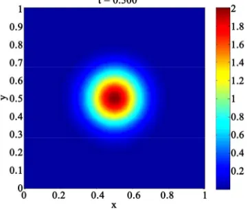
Remark 11. Based on the transport of the ionized spe-cies from the lower-left to the middle of the reactor, we see and influence of the species. The former circular concentration is spread out to a diffusive ellipse ere,
we c tric
eld
time- and spatial scales of the underlying transport and Maxwell equation. Via iterative splitting, we could couple the two equations systems together and reduce the numerical errors with additional iterative steps.
The results are given in 6 - 11.
. H an control the species in the reactor with a elec . Numerically, it is important to deal with the differ-fi
[image:11.595.323.521.77.243.2]ent
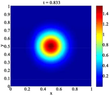
Figure 6. Gaseous concentration after t = 0.833.
Figu in
r first
fluence of the electric field.
[image:11.595.327.521.291.516.2]e 8. Gaseous concentration after t = 1.162 with a
Figure 9. Electric field after t = 1.162.
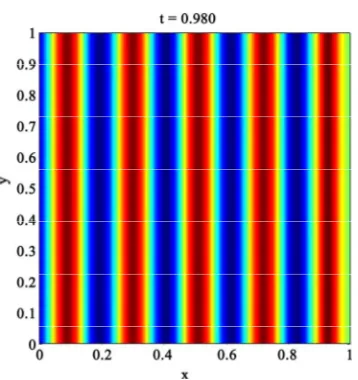
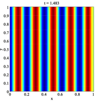
[image:11.595.77.268.317.482.2]Figure 10. Gaseous concentration after t = 1.483 with a first influence of the electric field.
[image:11.595.80.266.509.712.2] [image:11.595.321.526.517.693.2]174 J. GEISER
Figure 11. Electric field after t = 1.483.
6. Conclusions
We present a coupled model based on Maxwell and Transport equations, that can be applied for simplified transport model for an ionized gaseous species in a PECVD reator. Based the different scale models, we have included the optimal discretization methods for each separate equation. Splitting methods are used to couple the separate equations together. Further, we d cussed the splitting analysis. Numerical examples are presented to discuss the influence of decoupled and cou-pled systems. In future, we will analyze the validity of the models with physical experiments.
7. References
ience of Thin Films,” 2nd Edi-tion, Academic Press, San Diego, New York, Boston, London, 2002.
[2] J. Geiser and M. Arab, “Simulation of a Chemical Vapor Deposition: Mobile and Immobile Zones and Homoge-neous Layers,” Journal of Porous Media, Begell House Inc., Redding, 2009, Vol. 1, No. 2, pp. 123-143.
[3] L. Rudniak, “Numerical Simulation of Chemical Vapour Deposition Process in Electric Field,” Computers & Chemical Engineering, Vol. 22, Supplement 1, 1998, pp. 755-758.
[4] J. Van Roey, J. van der Donk and P. E. Lagasse, “Beam-Propagation Method: Analysis and Assessment,” Journal of the Optical Society of America, Vol. 71, No. 7, 1981, pp. 803-810. doi:10.1364/JOSA.71.000803
is-[1] M. Ohring, “Materials Sc
[5] M. D. Feit and J. A. Fleck Jr., “Analysis of Rib Waveguides and Couplers by the Propagating Beam Method,” Journal of the Optical Society of America A, Vol. 7, No. 1, 1990, pp. 73-79.
doi:10.1364/JOSAA.7.000073
[6] M. D. Feit and J. A. Fl Graded-Index O
eck Jr., “Light Propagation in ptical Fibers,” OSA Applied Optics, Vol. 17, No. 24, 1978, pp. 3990- 3998.
doi:10.1364/AO.17.003990
[7] L. Thylen, E. M. Wright, G. I. Stegeman, C. T. Seaton and J. V. Moloney, “Beam-Propagation Method Analysis of a Nonlinear Directional Coupler,” OSA Optics Letters, Vol. 11, No. 11, 1986, pp. 739-741.
doi:10.1364/OL.11.000739
[8] J. A. Fleck, J. R. Morris Jr. and M. D. Feit, “Time-de-pendent Propagation of High Energy Laser Beams through the Atmosphere,” Applied Physics, Vol. 10, No. 2, 1976, pp. 129-160. doi:10.1007/BF00896333
[9] M. Lax, J. H. Batteh and G. P. Agrawai, “Channeling of Intense Electromagnetic Beams,” Journal of Applied Physics, Vol. 51, No. 1, 1981, pp. 109-125.
328442 doi:10.1063/1.
0] G. I. Marchuk, “Some Applications of Splitting-up
and Comparion of Dif-[1
ods to the Solution of Mathematical Physics Problems,” Aplikace Matematiky, Vol. 1, 1968, pp. 103-132.
[11] G. Strang, “On the Constraction
ference Schemes,” SIAM J. Numerical Analysis, Vol. 5, No. 3, 1968, pp. 506-517. doi:10.1137/0705041
[12] K. Okamoto, “Fundamentals of Optical Waveguides,” Academic Press, New York, 2005.
[13] A Taflove, “Computational Electrodynamics: The Finite Difference Time Domain Method,” Arctech House Inc., 1995.
[14] J. P. Berenger, “A Perfectly Matched Layer for the Ab-sorption of Electromagnetic Waves,” J. Comp. Phys., Vol. 111, 2005, pp. 185-220.
[15] S. D. Gedney, “An Anisotropic Perfectly Matched Layer-Absorbing Medium for the Truncation of Fdtd Lat-tices,” IEEE Tran. Ant. Prop., Vol. 44, No. 12, 1996, pp. 1630-1639.
[16] W. Sha, X. Wu, M. Chen and Z. Huang, “Application of the High-Order Symplectic Fdtd Scheme to the Curved
ymplectic Integrator
.
Splitting
and C. Kelley, “Convergence of Three-Dimensional Perfectly Conducting Objects,” [17] T. Hirono, W. Lui, S. Seki and Y. Yoshikuni, “A Three-
Dimensional Fourth-Order Finite-Difference Time-Domain Scheme Using a S
Propagator,”
[18] J. Geiser, “Numerical Simulation of a Model for Trans-port and Reaction of Radionuclides, 2001,” Proceedings of the Large Scale Scientific Computations of Engineer-ing and Environmental Problems, Sozopol, 2001 [19] W. Hackbusch, “Iterative Losung Groser
Schwachbe-setzter Gleichungssysteme,” Teubner-Verlag, Stuttgart, 1993.
[20] I. Farago and J. Geiser, “Iterative
Operator-Methods for Linear Problems,” International Journal of Computational Science and Engineering, Vol. 3, No. 4, 2007, pp. 255-263.
[21] J. Kanney, C. Miller
Nonlinear Reactive Transport Problems,” Advances in Water Resources, Vol. 26, 2003, pp. 247-261.
doi:10.1016/S0309-1708(02)00162-8
[22] J. Geiser, “Weighted Iterative Operator-Splitting Methods: Stability-Theory,” Proceedings of the 6th International
Order Time-Integration Methods and Applications
ear Functional Analysis and Its Ap-for P
Conference, NMA 2006, Lecture Notes in Computer Sci-ence, Springer, Berlin, Vol. 4310, 2007, pp. 40-47. [23] W. H. Hundsdorfer and J. G. Verwer, “Numerical
Solu-tion of Time-Dependent AdvecSolu-tion-DiffusionreacSolu-tion
Equations,” Springer, Berlin, 2003.
[24] J. Geiser, “Iterative Operator-Splitting Methods with Higher
arabolic Partial Differential Equations,” Journal of Computational and Applied Mathematics, Elsevier, Am-sterdam, Vol. 217, 2008, pp. 227-242.
[25] E. Zeidler, “Nonlin