Abstract— Induction motors are widely used in most of the industrial applications due to their ruggedness, reliability and low cost. Even a small amount of improvement in efficiency will have a bigger effect in conserving energy. This paper incorporates an efficiency optimization scheme to operate the single phase induction machine at its maximum efficiency point. Efficiency is improved by operating the machine at an optimum slip. Optimum slip is obtained by testing the machine in open loop. Simulation results to prove the concept of optimum slip are presented and are validated through LabVIEW based implementation for a fan motor to operate it at its maximum efficiency point for a given speed. An online efficiency control is implemented using Perturb and Observe (P&O) algorithm so that errors in parameter estimation do not affect the performance.
Index Terms—Efficiency optimization, Optimum V/f, Perturb and Observe (P&O), Single Phase Induction Motors (SPIM)
I. INTRODUCTION
Among electrical motors, induction motors are the most used both for home appliances and in various industries. Most of the electrical energy produced is consumed by these motors. In an effort to improve the efficiency, there have been improvements in materials, design and construction techniques. However motor losses are still greatly dependent on control strategies, especially when the motor operates at light load.
Single Phase Induction Motors (SPIMs) is a highly efficient machine when operated close to its rated torque and speed. However, at light loads, no balance in between copper and iron loss, results in considerable decrease in efficiency. To achieve better efficiency induction motor has to be controlled by some control techniques. Variable frequency drives serve the purpose to a good extent but it is not economical to use inverters for a low rating motor as the cost of inverter might exceed the cost of motor.
Manuscript received July 24 , 2012; revised August 15, 2012.
K. Nidheesh Nair was with College of Engineering Guindy, Anna University Chennai, India-600025, Phone:091-8907116350; email:[email protected]
B. Umamaheswari is with the Department of Electrical, College of Engineering Guindy, Anna University Chennai, India-600025, Phone:091-044-22357803; email:[email protected]
Efficiency improvement of single phase capacitor run motor started with stator voltage control [1].The traditional voltage control technique was further modified to control the voltage of only main winding keeping auxiliary winding voltage constant [2].This reduces the harmonic content in the auxiliary winding and thus resulting in loss reduction. Although advancements in technology have enabled the employment of variable frequency drive for three phase ac machines, they have not been widely used in the single phase counter parts [5, 6, 7]. V/f control in SPIM does not provide constant torque operation for the entire speed range since the maximum available torque rapidly decays below half of the base frequency.
An efficiency improvement control scheme for capacitor start and run machine by operating at optimum slip was proposed [3, 4, 8]. In this paper, the concept of optimum slip is being incorporated with the interfacing capabilities of LabVIEW for efficiency optimization. Also it is proved that the efficiency at light loads can be matched to a good extend with that of full load. Perturb and Observe (P&O) method is adopted to account for uncertainties in parameter estimation.
II. EQUIVALENT CIRCUIT OF CAPACITOR START AND RUN SPIM
Let fa
E
Forward voltages of the magnetizing branch of the auxiliary windingba
E
Backward voltages of the magnetizing branch of the auxiliary windingfm
E
Forward voltages of the magnetizing branch of the main windingbm
E
Backward voltages of the magnetizing branch of the main windingmf
E
Forward induced electromotive force of main windingmb
E
Backward induced electromotive force of main windinga
I
Auxiliary windings current mI
Main windings currentLabVIEW Based Performance Optimization of
Single Phase Induction Motors
fm
I
Forward currents of magnetizing branches in main windingbm
I
Backward currents of magnetizing branches in main windingin
I
Total input stator current elP
Total electrical losses inP
Input power mP
Output mechanical power cfR
Forward core loss equivalent resistance cbR
Backward core loss equivalent resistances
Motor slip opts
Optimum motor slip eT
Electromagnetic torqueV
Supply voltage mV
Main winding voltage aV
Auxiliary winding voltage cZ
Capacitor winding impedance mZ
Main winding impedance aZ
Auxiliary winding impedance fZ
Forward stator impedance in main winding bZ
Backward stator impedance in main winding
Turns ratio of auxiliary to main windingi
Winding current phase difference opti
Winding current phase difference optimum value e
Electrical angular speed m
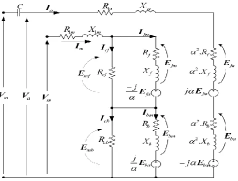
Mechanical angular speed [image:2.595.52.290.459.640.2]Single phase capacitor start and run equivalent circuit is given by Fig. 1 [4].
Fig. 1. Equivalent circuit of capacitor start and run SPIM
Motor voltage equation according to the equivalent circuit is given by
2
( ( )) )
a c a f b a fm f bm b
VI Z Z Z Z j I Z j I Z (1)
( )
m m fm f bm b a f b
VI Z I Z I Z j I Z Z (2)
where
in m
V
V
V
(3) Current through the forward and backward component can be written asfm cf ( m a)
cf f R
I I j I
R Z
(4)
bm cb ( m a)
cb b R
I I j I
R Z
(5) Using (4) and (5) in (1) and (2) and simplifying, a ratio between winding currents is obtained as
2
( )
( ) ( )
m tf tb tf tb a
m c a f b tf tb tf tb
Z Z Z j Z Z I
I Z Z Z Z Z Z j Z Z
(6)
where
Z
tf
Z
f||
R
cfandZ
tb
Z
b||
R
cb.From (6) we can conclude that the ratio of winding currents is a function of frequency and slip.
a ( , ) m
I
r f s
I (7)
From (4) and (5), the current ratios Ifm/Im and Ibm/Im are function of frequency and slip
( , )
fm f mI
r
f s
I
(8)( , )
bm b m
I
r f s
I
(9) Electromagnetic torque of an SPIM is represented by
2 2
R
fm a e f bm a e b
e
e e
I j I Z I j I R Z
T
(10)
From (10), it can be inferred that the electromagnetic torque is also a function of slip and frequency.
2 ( , ) in e I T
Func f s
(11) and electrical power loss is obtained as
2
cos
el in m in in e m
P
P
P
I Z
T
(12) where((
)
(
))
(1
)
m f f b b f b
in in
Z
r Z
r Z
j r Z
Z
V
Z
I
r
(13)
(
cos
( , )
)
el e in m
P
T Z
Func f s
(14)( , )
el e
|
0
e e el
T
P
s
(16)( , )
|
|
0
e e
e el
T opt
P
Func f s
s
s
s
s
(17)From (17), the optimum slip is a function of frequency under a specific load.
III. SIMULATION RESULTS USING MATLAB/SIMULINK
Simulation results of capacitor start and run motor in open loop is shown in figure [2]. Here the SPIM is made to operate at different slip by varying voltage for a given load and frequency and the losses at each case have been tabulated. The same experiment has been carried out for different load keeping the frequency same as that of fundamental as we are not interested in variable frequency control due to reasons mentioned earlier. The simulation parameters used are given in TABLE I.
TABLEI
MOTOR PARAMETERSUSEDINSIMULATION
Parameters Values Parameters Values
R1m 4 Ω L1m 0.0203 H
R1a 6.5 Ω L1a 0.0210 H
R2
’ 3.61 Ω
L2 ’
0.0304 H α 1.1293 Lm 0.1954 H
C 40 µF Jm 0.001424 Kgm2
f 50 Hz Vrated 220 V
P 4 Irated 5.8 A
[image:3.595.302.551.49.220.2]The results obtained using MATLAB are plotted in MS Excel and given in figure [2].
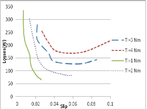
Fig. 2. Variation of machine losses (in watts) with slip
Figure [2] gives the variation of losses(in watts) with different slips for loads of 1Nm, 2Nm, 3Nm and 4Nm. The slip at which losses are minimum varies with load. It is observed from the plot that the variation of optimum slip do not vary considerably with small variations in load.
Fig. 3. Variation of efficiency (in %) with slip
Figure [3] gives an estimation of efficiency improvement when different loads are applied to the machine. Maximum improvement in efficiency is observed at light loads. Also it can be validated that the induction motors can be operated at full load efficiency even in light load conditions. In the case of 1 Nm load applied to the machine the improvement in efficiency is 28% which is quiet large. There can be considerable saving of power in industries especially during light load conditions by employing this technique than the traditional delta to star change over.
IV. LABVIEW BASED EFFICIENCY MONITORING
For experimental verification, a fan motor has been used. The name plate details are presented in TABLE II. Unlike the case in simulation, fan motor’s load is proportional to the square of the speed. It is expected and experimentally verified that the concept of optimum slip with fixed frequency cannot be applied for fan type motors. Hence for fan type motors, variable voltage and variable frequency control is applied. Even though the use of inverters for a fan motor is not economical, but for higher rating machines (both single/three phase) with similar characteristics it can be applied. Hence for hardware implementation fan motor is connected to an inverter and the control signals are given using LabVIEW.
Fig. 4. Graph showing variation of input power(Pi) and ω3normalised
[image:3.595.46.294.317.398.2] [image:3.595.47.291.456.636.2] [image:3.595.305.550.568.752.2]Figure [4] shows the variation of input power with ω3norn
for a fan motor for different frequencies. As described earlier, load is proportional to the square of the speed and hence output power is proportional to the cube of the speed. The slope of the curve given in figure [4] gives the efficiency. It is observed from the graph that there is an optimum V/f for the machine at which it gives maximum efficiency. For lower speed range, it is better to operate the machine at lower frequency to get maximum efficiency. Controller implementation is done from the values obtained from experimental results. A simple closed loop control is implemented using LabVIEW. An inverter is used to obtain variable voltage and frequency. Pulses are generated from LabVIEW to vary the voltage and frequency in accordance with the maximum efficiency operation. In the actual implementation, the designed values may not be the optimum efficiency point. Hence, Perturb and Observe (P&O) algorithm to retune the voltage (with frequency kept constant at optimum point) is used to improve the efficiency.
TABLEII
NAME PLATE DETAILS OF FAN MOTOR USED
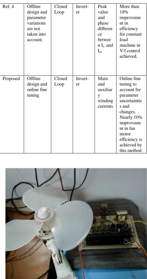
Hardware setup is shown in figure [5] and figure [6]. A comparison of the presented technique with the existing technique is presented in TABLE III.
TABLEIII
COMPARISON OF EXISTING TECHNIQUES WITH THE PRESENTED
Referen ce No
Design Contro
l
Conve rter
Measu red Variab les
Advantage s
Ref. 2 Offline without considerin g parameter variations
Open loop
Triac Im Reduced
harmonics in auxiliary current.6% improveme nt in efficiency for fan motor achieved by this technique. Ref. 3 Offline
design and offline parameter variation
Closed loop
Triac Ratio of currents Ia and
Im
Nearly 28% improveme nt in efficiency is achieved for constant load.
Ref. 4 Offline design and parameter variations are not taken into account.
Closed Loop
Invert-er
Peak value and phase differen ce betwee n Ia and
Im
More than 18% improveme nt in efficiency for constant load machine in V/f control achieved.
Proposed Offline design and online fine tuning
Closed Loop
Invert-er
Main and auxiliar y winding currents
[image:4.595.306.549.45.505.2]Online fine tuning to account for parameter uncertaintie s and changes. Nearly 10% improveme nt in fan motor efficiency is achieved by this method.
[image:4.595.46.289.349.399.2]Fig. 5. Hardware setup with fan and inverter
Fig. 6. Hardware setup interfaced using LabVIEW
Variables Values Variables Values
C 1.5µF Nrated 1300 RPM
frated 50 Hz Vrated 220 V
Poles 4 Irated 0.239 A
[image:4.595.43.550.531.746.2] [image:4.595.255.541.555.744.2]V. CONCLUSION
In this paper, single phase induction motor efficiency improvement is done by operating the machine at optimum slip. Simulation results are included for different loads and variations of losses with slip in each case are plotted. Result shows a considerable improvement in the efficiency of motor especially at light loads. Fan motor is used for hardware implementation using LabVIEW. Perturb and Observe (P&O) algorithm is used for online efficiency optimization.
REFERENCES
[1] T. A. Lipo and D. W. Novotny, “Induction machine efficiency improvement by voltage control”,1982
[2] K Sundareswaran, “An improved energy saving scheme for capacitor-run induction motors,” IEEE Transactions on Industrial Electronics, Feb. 2001.
[3] C. Mademlis, I. Kioskeridis, and T. Theodoulidis, “Optimization of single-phase induction motors –Part I:Maximum energy efficiency control, IEEE Transactions on Energy Conversions
[4] S. Vaez-Zadeh and B. Zahedi, “Efficiency optimization control of single phase induction motor drives,” IEEE Transactions on power electronics, April 2009.
[5] F. Blaabjerg, F. Lungeanu, K. Skaug, and A. Aupke, “Comparison of variable speed drives for single-phase induction motors ,” Power Convers.
Conf., 2002
[6] W. H. Yeadon and A. W. Yeadon,” Handbook of Small Electric Motors” New York: McGraw-Hill, 2001.
[7] I. Boldea and S. A. Nasar, “The Induction Machine Handbook”. New York: CRC Press, 2001.