Abstract— In an attempt to increase distillation yield per unit evaporation area by decreasing the thermal inertia of the water mass, a new type of multi-stage solar still of low inertia was designed, fabricated and tested. The energy balance equations for various parts of the still were solved by Gauss-seidel iteration method. Computer model was made to predict the performance of the still and experimentally validated. The computer model was used to estimate the annual performance and pay back period of the still for Indian city of Ludhiana. At optimum combination of absorption area of solar water heater and evaporation area, the annual distillate yield and annual average performance ratio for the still were 2223.0 litres/m2 aperture area and 0.73 respectively assuming 300 clear days. Annual average performance ratio of distillation unit alone is 2.73. The pay back period of the still was estimated to be three years.
Index Terms— low inertia solar still, multi-stage solar still, solar still
I. INTRODUCTION
ATER is a basic necessity for all living beings along with food and air. Man has been dependent on rivers, lakes and underground water reservoirs for fresh water requirements in domestic life, agriculture and industry. However, use of water from such sources is not always possible or desirable on account of the presence of large amount of salts and harmful organisms. The impact of many diseases affecting mankind can be drastically reduced if fresh hygienic water is provided for drinking. Diversity of approaches are used for separation of salts from saline water such as reverse osmosis, electro dialysis, solvent extraction, flash distillation etc. However, these methods are expensive for the production of small amount of fresh water. Solar energy can be used for distillation purpose where weather conditions are favorable and demand is not too large.
Fernandez and Chargoy [1] built a solar still consisting of array of solar water heaters of 50 m2 aperture area and a multi-stage distillation unit with eight trays including the
Manuscript received Oct. 12, 2011;
Prem Singh is with the Guru Nanak Dev Engineering College, Ludhiana, Punjab, India (phone: +91-9464190665; e-mail: [email protected]). Parmpal Singh was with the Punjab Agricultural University, Ludhiana, Punjab, India. He is now with the Ludhiana Group of Colleges Vill. Mann, Ludhiana, Punjab, India (e-mail: [email protected]).
Jagdeep Singh is with the Guru Nanak Dev Engineering College, Ludhiana, Punjab, India (e-mail: [email protected])
Ravi Inder Singh is with the Guru Nanak Dev Engineering College, Ludhiana, Punjab, India (e-mail: [email protected])
Krishnendu Kundu is with the Mechanical Engineering Research and Development Organization , Ludhiana, Punjab, India (e-mail: [email protected] )
bottom tray. On a typical day, total experimental yield was 41.1 litres while theoretically it was found to be 44.7 litres. Adhikari et. al. [2] prepared a computer simulation model for the steady-state performance of a multi-stage stacked solar still. The experimental and theoretical distillate yields were 0.64, 2.0 and 0.646, 2.207 l/hr at 358 and 890 watts of heat supplied, respectively. Sangeeta Suneja [3] used a computer simulation model to solve the energy balance equations for a multi-basin inverted absorber distiller unit. The effect of reuse of latent heat from vaporization from respective lower basins on daily yield was studied for optimization of number of effects. It was observed that when the number of basins is increased beyond seven, there is only a marginal increase in the yield. Jubran [4] developed a mathematical model to predict the productivity and thermal characteristics of a multi-stage solar still with an expansion nozzle and recovery in each stage of the still. This model was used to conduct a parametric investigation on the proposed solar still. The results were obtained with heat input in the range of 100-1000 watt, which is equivalent to solar insolation of 120-1200 W/m2 when a 1.2m2 solar collector is used. Pierre Le Goff [5] reported a distillation unit which is stack of six rectangular cells in thermal series. In each cell, which is a 4 cm thick film of salty water is partially evaporated as it trickles over a heated vertical wall. The vapor produced is condensed on the opposite wall of the cell. The heat evolved by this condensation is used to evaporate the film trickling on the other side of the same plate, in the next cell. The unit produces about 20 liters of distilled water per m2, per standard day, under the same conditions of sunshine that would give a production of 2.5 to 3 liters/m2 day in a conventional, "single basin" solar still.
In the present study, effort has been made to increase the distillation yield of multi-stage solar still by decreasing thermal capacity of water mass in the trays. This was achieved by modifying the geometry of trays. A computer model was developed for prediction of distillation yield as a function of solar radiation and ambient temperature for any place. The model was experimentally validated by conducting experiments on the still under environment conditions of Ludhiana.
II. DESCRIPTIONOFTHESYSTEM
The schematic diagram of the low inertia multi-stage solar still is shown in Fig. 1. It consists of a heating unit (flat plate collector) and a distillation unit. The heating unit
Performance Evaluation of Low Inertia
Multi-Stage Solar Still
Prem Singh, Parmpal Singh, Jagdeep Singh, Ravi Inder Singh and Krishnendu Kundu
W
of the experimental low inertia multi-stage solar still is a flat plat collector of a fin and tube type with single glass cover. The collector of size 229 × 125 × 14 cm (aperture 216 × 107 cm) is made of galvanized iron sheet. Its absorber is blackened with black board paint. The total number of riser tubes is 15, each of diameter 15 mm. Each riser tube is connected to two header tubes one at the top
and other at bottom, each of 35 mm diameter. Flat plate collector is insulated at bottom with glass wool of thickness 10 cm. The insulation of glass wool on sides is represented by the difference in dimensions of the outer frame and aperture. The lower and upper header pipes extend out of collector to act as inlet and outlet of the collector respectively.
Distillation unit of low inertia multi-stage solar still (Fig. 2) consists of three main parts namely: bottom tray, upper trays and collecting channels made from galvanized iron
sheet. The size of bottom tray is 70×70×10 cm. It has two pipes in its opposite sides for the circulation of hot water of collector though it. These pipes are diagonally opposite. The depth of water in the bottom tray is kept 3 cm with the help of waste water pipe. The total mass of water in the bottom tray is 14.7 kg. One of the five upper trays each of size 70×70×5 cm is shown in Fig. 3(a). The bottom surface of each tray is bent at four places along one of its sides. So the bottom surface of each tray is sub divided into eight inclined surfaces, each inclined at an angle of 15° with horizontal. This was done to ensure that trays hold small amount of water in them and it also facilitates collection of condensate from the down facing surface. Water is fed to all
the trays though top most tray. The quantity of water filled in each tray except bottom tray is such that it is just sufficient to cover the bottom surface. There is provision in each tray so that when it is filled to the desired level, water starts flowing to the tray immediately below this tray. This way, all the trays get filled with water. Waste water is discharged out from the bottom tray through an overflow provided for this purpose. The mass of water in each upper tray is 6.125 kg. Five collecting channels (one such channel is shown in Fig. 3(b)) are provided to collect distilled water from the down facing surface of each tray excluding the bottom tray.
Collecting channel having a slope of 1:50 is placed on the bottom tray, the upper tray is fitted on bottom tray with nuts and bolts by providing rubber seal in between them to make leak proof unit. In the similar way remaining four upper trays and channels are assembled one upon other. This assembled unit is placed in another tank of size 80×80×40 cm, which provides insulation of 5 cm of glass wool on all vertical sides and 10 cm bottom side. The top tray is exposed to atmosphere.
III. EXPERIMENTATION
The still was tested in the month of December at Indian city of Ludhiana (latitude 31oN). Collector of the still was kept inclined at 45o facing south. Hot water of collector circulates through the bottom tray of the still due to thermosyphon effect. Ambient temperature, solar radiation on glass cover and horizontal surface, evaporating and condensing surface temperatures and distillation yield of each stage were recorded after every hour.
IV. COMPUTER MODEL
The following assumptions were made while making computer model for the still. (i) Mean water temperature in the bottom tray of the low inertia multi-stage solar still and in flat plate collector is same. (ii) Water is at uniform temperature in each tray. (iii) Heat capacity of glass cover of solar water heater is negligible. (iv)The system is air and vapour tight. (v) Evaporating and condensing surfaces are infinite parallel plates. (vi) The temperature of top most
Fig.2: Cross-section of distillation of low inertia multi stage solar still
Fig.1: Low inertia multi stage solar still
Fig.3 (a): Tray of distillation unit of low inertia multi-stage solar still
Fig.3 (b): Collecting channel under each tray of distillation unit of low inertia multi-stage solar still
tray is almost equal to the ambient temperature. Hence heat stored in the water mass of this tray, heat lost from sides and heats lost to ambient through evaporation have been neglected. The energy balance equations per unit area for the different elements are written as follows.
For bottom or 1st tray:
Heat supplied by collector to still =
Heat transfer from 1st to 2nd
tray by
convection, evaporation and radiation
+
Heat loss to
ambient from sides of 1st tray
+ Heat loss to ambient from bottom of 1st tray
+ Heat stored in water mass in 1st tray
Qcs = Q1,2 + Qs1 + Qb1 + Qw,1
--- (1)
For 2nd tray:
Heat transfer from 1st
to 2nd tray by
convection, evaporation and
radiation =
Heat loss to ambient from
sides of 2nd
tray +
Heat transfer from 2nd
to 3rd tray by
convection, evaporation and radiation + Heat stored in water mass in 2nd
tray
Q1,2 = Qs2 + Q2,3 + Qw,2
--- (2)
For 3rd tray:
Heat transfer from 2nd
to 3rd tray by
convection, evaporation and
radiation =
Heat loss to ambient from
sides of 3rd
tray +
Heat transfer from 3rd
to 4th tray by
convection, evaporation and radiation + Heat stored in water mass in 3rd
tray
Q2,3 = Qs3 + Q3,4 + Qw,3
--- (3)
For 4th tray:
Heat transfer from 3rd
to 4th tray by
convection, evaporation and
radiation =
Heat loss to ambient from
sides of 4th
tray +
Heat transfer from 4th
to 5th tray by
convection, evaporation and radiation + Heat stored in water mass in 4th
tray
Q3,4 = Qs4 + Q4,5 + Qw,4
--- (4)
For 5th tray:
Heat transfer from 4th
to 5th tray by
convection, evaporation and
radiation =
Heat loss to ambient from sides of 5th
tray +
Heat transfer from 5th
to 6th tray by
convection, evaporation and radiation + Heat stored in water mass in 5th
tray
Q4,5 = Qs5 + Q5,6 + Qw,5
--- (5)
For 6th tray:
Heat transfer from 5th to 6th tray by
convection, evaporation and radiation =
Heat transfer from 6th to ambient by convection
and radiation
Q5,6 = Q6,a
--- (6)
Heat transfer from evaporating surface to condensing surface:
Qi,i+1 = (hr(i,i+1) + hc(i,i+1) + he(i,i+1)) × Abi × (Ti - Ti+1)
i = 1 to 5 ---7) Heat loss to ambient from sides of trays:
Qsi = Usi × Asi × (Ti - Ta) i = 1 to 5 --- (8)
Heat loss to ambient from bottom of 1st tray:
Qb1 = Ub1 × Ab1 × (T1 - Ta) --- (9)
Heat loss to ambient from top tray:
Q6,a = (hc(6,a) + hr(6,a) ) × Ab6 × (T6 - Ta) ---(10)
Putting the values of Qi,i+1, Qsi, Qb1 and Q6,a from
equations (7) to (10) in equations (2) to (6), we get the following simultaneous linear equations:
h1,2×Ab1×T1–(h1,2×Ab1 + h2,3×Ab2 + hs2×As2 + mw×cw / dt)×T2 +
h2,3×Ab2×T3 + mw×cw×T′1/dt + hs2×As2×Ta = 0 ----(11)
h2,3×Ab2×T2–(h2,3×Ab2 + h3,4×Ab3 + hs3×As3 + mw×cw / dt)×T3 +
h3,4×Ab3×T4 + mw×cw×T′2/dt + hs3×As3×Ta = 0 ----(12)
h3,4×Ab3×T3–(h3,4×Ab3 + h4,5×Ab4 + hs4×As4 + mw×cw / dt)×T4 +
h4,5×Ab4×T5 + mw×cw×T′3/dt + hs4×As4×Ta = 0 ----(13)
h4,5×Ab4×T4 – (h4,5×Ab4 + h5,6×Ab5 + hs5×As5 + mw×cw / dt)×
T5 + h5,6×Ab5×T6 + mw×cw×T′4/dt + hs5×As5×Ta = 0 ----(14)
h5,6 × Ab5×T5 – (h5,6 × Ab5 + h6,a × Ab6) × T6 + h6,a ×Ab6 ×
Ta = 0 --(15)
Heat supplied from still to collector (Qsc):
Qsc = Qac - Qlc - (mw×cw)c × ( Tc(t)-Tc(t-dt) ) / dt ---16)
Distillation yield:
Y(i) = he(i,i+1) × Abi × (T(i)-T(i+1)) × dt / Lw Kg (or litres) --(17)
To predict the distillation yield of the still theoretically, a computer program was written in quick basic language for the solution of the energy balance equations of the still elements. The flow chart is shown in Fig.4. The input parameters to the computer program include the climatic parameters (solar radiation, ambient temperature), thermo-physical parameters (properties of air & water, thermal conductivity etc.) and configurational parameters (dimensions of the still & solar water heater).
Initially, the temperatures of the different components of the still are assumed to be equal to the ambient air temperature at the sunrise time of the collector. Equations (2) to (6) are solved by Gauss-seidel iteration method for different tray temperatures. Then comparison is made between the heat supplied by collector from equation (1) and (16) respectively. If they are equal then this is the required condition. Then distillation yield of each tray of the still was determined from equation (17). This process is repeated for an additional time interval dt. For validation of computer model, measured solar radiation and ambient temperature data was used in the program. To predict yearly performance of the still, the validated computer model was run for the representative day of every month assuming 300 clear days in a year. The computer model was also run at different values of evaporation area of trays to find maximum distillate yield and hence to find optimum evaporation area of individual trays.
V. RESULTS AND DISCUSSION
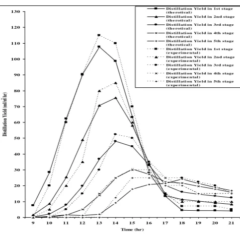
Solar radiation on aperture and ambient temperature for a given day are shown in Fig. 5. Theoretical and experimentally measured water temperatures in different trays of low inertia multi-stage solar still are shown in Fig. 6. Maximum water temperature achieved is 62, 54, 48, 41 and 35oC in 1st, 2nd, 3rd, 4th and 5th tray respectively. Distillation yield of different stages of low inertia multi-stage solar still is shown in Fig. 7 and 8. The distillation yield in lower trays is higher during daytime due to higher water temperature and large temperature different in these trays. During evening (after sunset) distillation in upper trays is higher than in lower trays. This is due to the fact that though lower trays are at higher temperature, there is
Fig. 8 Distillation yield (experiemental) in every stage of low interia multi-stage solar still as a function of time
0 20 40 60 80 100 120 140
9 10 11 12 13 14 15 16 17 18 19 20 21 Time (hr) D is ti ll a ti o n y ie ld ( m l/ m 2 h r )
Distillation yield in 1st stage Distillation yield in 2nd stage Distillation yield in 3rd stage Distillation yield in 4th stage Distillation yield in 5th stage
large temperature difference in the upper trays than in lower trays. The predicted distillation yield is about 10% higher than the experimental yield. This is due to higher theoretical temperatures of trays than experimentally measured temperatures.
Fig.5: Variation of solar radiation on aperature (inclined at angle of 45 degree) of low inertia multi-stage solar still and ambient
temperature as function of time
Performance ratio of the still defined as latent heat required to evaporate given quantity of water to the energy falling on the aperture of the collector, is 0.264. This low value is due to the fact that ratio of evaporation area to the aperture area for the still is low. Maximum yield was found at an optimum evaporation area of 1.5 m2 of each of five trays (ratio of evaporation area of individual tray to the collector area is 0.75). With this area, performance ratio of low inertia multi-stage solar still and distillation unit alone are 0.67 and 2.73 respectively. The performance ratio of the distillation unit is quite high. This is due to the lesser thermal inertia of the distillation unit due lesser quantity of water in the trays.
Monthly average distillation yield of low inertia multi-stage solar still is shown in Fig. 9. Annual yield was calculated for the still by computing yield for typical day of every month from the computer model. Yield of typical day of the year was calculated by averaging these values. Then annual yield at Ludhiana was calculated by assuming 300 clear days in a year. The annual distillation yield per square metre aperture area and annual performance ratio for low inertia multi-stage solar still, corresponding to optimum
Fig.6: Hourly variations of the theoretical and experimental water temperature in different trays of low inertia multi-stage solar still
evaporation area of 1.5 m2, are 2223 litres and 0.73 respectively. Performance ratio of distillation unit alone is 2.73 under these conditions. Pay back period of the still was estimated to be three years.
Fig.8: Distillation yield (experimental) in every stage of low inertia multi-stage solar still as function of time
VI. CONCLUSIONS
A multi-stage solar still with low inertia was designed and
Fig.7: Hourly variation of distillation yield (Experimental and Theoretical) in different stages of low inertia multi-stage solar
still as function of time
fabricated. Also a computer mode to predict the performance of multi-stage solar still has been developed. This model has been validated by comparison with the experimental results obtained at Ludhiana, hence can be
Fig. 6 Hourly variation of the ortical and e xpe rime ntal wate r te mpe rature in diffe re nt trays of low ine rtia multi-stage
solar still as function of time
10 20 30 40 50 60 70
9 10 11 12 13 14 15 16 17 18 19 20 21
Time (hr) T em p er at u re ( oC)
1st tray te mp. the orti cal 2nd tray te mp. the orti cal
3rd tray te mp. the orti cal 4th tray te mp. the orti cal
5th tray te mp. the orti cal 1st tray te mp. e xp.
2nd tray te mp. e xp. 3rd tray te mp. e xp.
4th tray te mp. e xp. 5th tray te mp. e xp.
Fig. 7 Hourly variation of dis tillation yield (Th. and Exp. ) of diffrrent s tages of low inertia multi-s tage s olar s till as a function of time
0 10 20 30 40 50 60 70 80 90 100 110 120 130
9 10 11 12 13 14 15 16 17 18 19 20 21
Time (hr) Di st ill at io n Yi el d (m l/m
2 h
r)
Di s ti l l ati on Yi e l d i n 1s t s tage (th e roti cal )
Di s ti l l ati on Yi e l d i n 2n d s tage (th e roti cal )
Di s ti l l ati on Yi e l d i n 3rd s tage (th e roti cal )
Di s ti l l ati on Yi e l d i n 4th s tage (th e roti cal )
Di s ti l l ati on Yi e l d i n 5th s tage (th e roti cal )
Di s ti l l ati on Yi e l d i n 1s t s tage (e xpe ri m e n tal )
Di s ti l l ati on Yi e l d i n 2n d s tage (e xpe ri m e n tal )
Di s ti l l ati on Yi e l d i n 3rd s tage (e xpe ri m e n tal ) Di s ti l l ati on Yi e l d i n 4th s tage (e xpe ri m e n tal ) Di s ti l l ati on Yi e l d i n 5th s tage (e xpe ri m e n tal )
Fig. 9 Theoretically predictied distillation yield for low interia multi-stage solar still for the clamitic condition of Ludhiana on typical day of each month 0 2000 4000 6000 8000 10000 12000
Jan Feb Mar Apr May Jun Jul Aug Sep Oct Nov Dec
Month D is ti ll a ti o n Y ie ld ( m l/ m 2-d a y )
Distillation yield of multi-stage solar still
Fig.9: Theoretically predicted distillation yield for low inertia multi-stage solar still for the climatic condition of Ludhiana on typical day of each month
Fig. 5 Variation of solar radiation on aperature ( inclined at an angle of 45o) of low inertia multi-stage solar still
and ambient temperature as a function of time
0 5 10 15 20 25 30
9 10 11 12 13 14 15 16 17 18 19 20 21
Time (hr) T em p er a tu re ( oC) 0 100 200 300 400 500 600 700 S o la r R a d ia ti o n ( W/ m 2)
Ambient Temperature Solar Radiation
[image:5.595.56.289.119.243.2] [image:5.595.308.550.306.542.2] [image:5.595.56.283.554.696.2] [image:5.595.317.544.635.751.2]used for predicting the system performance for any other place. The new design of low inertia multi-stage solar still shows great potential in terms of distillation yield.
NOMENCLATURE A Area (m2)
c Specific heat (J/kg°C)
dt Time interval (s)
dT Change in temperature (°C) h Heat transfer coefficient (W/m2°C)
I Solar radiation on aperture (W/m2) L Latent heat of Water (J/kg) / length (m)
m mass (kg)
n Day of the year (n = 1 for 1st January) P Water saturation pressure (N/m2) Q Heat loss / heat supplied / heat stored (W) R Reflectivity
r Tilt factor T Temperature (°C)
U Overall heat transfer coefficient (W/m2oC)
Y Distillation yield (litres) Greek symbols
α Absorptivity
Hour angle (deg)
Reflectivity of ground, density (kg/m3)
Transmitivity
Angle of incidence (deg)
Slope of collector with horizontal (deg)
Hour angle (deg) Latitude angle (deg)
Declination angle (deg) / thickness (m)
εeff Effective emissivity
ε Emissivity
σ Stefanboltzman constant (W/m2K4)
Subscripts
a ambient
ac absorbed by collector ag absorbed by glass b beam radiation
bi from / (corresponding to) bottom of ith tray
c collector
cs collector to still
c(i,i+1) convective from ith to (i+1)th tray
d diffuse radiation
e(i,i+1) evaporative from ith to (i+1)th tray
g glass
i a given tray being identified by a number / insulation i,i+1 from ith to (i+1)th tray
lc loss from collector r reflected radiation
r(i,i+1) radiative from ith to (i+1)th tray sc still to collector
t time
si from / (corresponding to) sides of ith tray
w water
6,a from sixth tray to ambient Superscript
after time interval dt
APPENDIX
The solar radiation falling on horizontal surface was converted to that falling on inclined surface (equations. a to g):
Iag = I × g ……….. (a)
(Degree)=23.45sin[360(284+n)/365]…… (b)
sin()sin() + cos()cos()cos() rb = --- .… (c)
sin()sin() + cos()cos()cos()
rd = ( 1 + cos () ) / 2 ……… (d)
rr = ( 1 - cos () ) / 2 ……… (e
I = ( Ig - Id ) rb + Id rd + Ig rr ……… (g)
Where, Ig = Global (total) radiation flux on horizontal surface
Id = Diffuse radiation flux on horizontal surface
g = 1 - g - Rg
= Cos-1 {Sin() × Sin(-) + Cos() × Cos() × Cos(-)}
hc(i,i+1) = 0.844×[ (Ti-Ti+1) + (Pi-Pi+1)×( Ti+273.15 ) / ( 268900-Pi ) 1/3
W/m2°C i = 1 to 5
Pi = exp25.317-5144 / (Ti + 273.15) N/m2
Pi+1 = exp25.317-5144 / (Ti+1 + 273.15) N/m2
he(i,i+1)=16.273×10 -3
×hc(i,i+1)×(Pi-Pi+1)/(Ti-Ti+1) W/m 2°
C
hr(i,i+1) = eff × × ( Ti + 273.15 ) 2
+ ( Ti+1 + 273.15 ) 2
×
( Ti + 273.15 ) + ( Ti+1 + 273.15 ) W/m 2°
C
eff = 1/ ( 1 / g + 1 / w – 1 )
h i,i+1 = hc(i,i+1) + he(i,i+1) +hr(i,i+1) W/m 2°
C
Usi or Ub1 = 1 / (1 / hs + i / Ki )
REFERENCES
[1] Fernadez Jose L. and Chargoy Norberto (1990) Multi-stage indirectly heated solar still. Solar Energy 44(4): 215-223.
[2] Adhikari R.S., Kumar Ashvini and Sootha G.D. (1995) Simulation studies on a multi-stage stacked tray solar still. Solar Energy 54(5): 317-325.
[3] Sangeeta Suneja and G. N. Tiwari (1998) Optimization of number of effects for higher yield from an inverted absorber solar still using the Runge-Kutta method. Desalination
[4] Jubran B.A., Ahmed M.I. Ismail A.F. and Abakar Y.A. (2000) Numerical modeling of a multi-stage solar still. Energy Conversion and Management 41: 1107-1121.
[5] Pierre Le Goff, Jacqueline Le Goff and M. Razak Jeday (2001) Development of a rugged design of a high efficiency multi-stage solar still. Desalination
[6] Sukhatme S.P. (1997) Solar energy principles of thermal collection and storage. Tata McGraw-Hill Publishing Company Limited, New Delhi.
[7] Duffie J.A. and Beckman W.A. (1980) Solar engineering of thermal process. John Wiley & Sons, New York.
[8] Incropera Frank P. and Dewitt David P. (1981) Fundamentals of heat transfer. John Wiley and Sons, New York:
[9] Malik M.A.S., Tiwari G.N., Kumar A. and Sodha M.S. (1982) Solar Distillation, A practical study of a wide range of stills and their optimum design, construction and performance. Pergamon Press, Oxford.
[10]Tiwari G.N. and Suneja Sangeeta (1997) Solar thermal engineering systems. Narosa Publishing House, New Delhi.