928
©IJRASET: All Rights are Reserved
A New Control Method for DSTATCOM
Considering Transmission Reactive Power Flow
G Srinivasarao1 1
M.TECH
Abstract: This paper exhibits a new control method for a distributed static compensator (also called as distributed STATCOM or DSTATCOM), configured to control the reactive power flow at a point in a transmission system. This new control method takes Into account the operating VAr limits to finding the steady-state output of the DSTATCOM. The new control method applies a slow reset regulator (SRR) to slowly bias the VAr set point of the DSTATCOM master controller to maintain its steady-state output within a target bandwidth. The operating result maintains an approximate VAr reserve point from the DSTATCOM for dynamic events in the system. This paper also proposed a new algorithm to calculate the operating constraints of the SRR that reflect the VAr flow at the local or remote point in the transmission system and the allowable VAr thresholds for that flow. These considering thresholds can be utilized to the full extent to lower the steady-state output of the DSTATCOM, maximize its VAr reserve for dynamic events and reduce equipment and associated system operating losses. The topology and control algorithm are validated through extensive simulation and experimental results.
Index Terms: Distributed STATCOMs or DSTATCOMs, FACTS, Proportional-plus-integral (PI) controller, Reactive power regulator, Slow reset regulator (SRR), Slow susceptance regulator, STATCOM, SVC, VAr reserve regulator, ANN.
I. INTRODUCTION
The slow reset regulator (SRR) (also called as a slow susceptance regulator, reactive power regulator, or VAr reserve regulator) has been presented or used for some flexible ac transmission systems devices, such as static VAr compensators (SVC) or static compensators (STATCOM) for system voltage-control applications [1]–[3].
Many SVC or STATCOM applications for an appropriate reactive power (VAr) reserve capacity to overcome dynamic events to increase system voltage stability. The SRR in the SVC or STATCOM control method is used to slowly return the SVC or STATCOM to a predefined value (which is usually a low output level reactive power rating) of reactive power output following a contingency, so that it has maximum reactive reserve for dynamic events. These applications are based on a voltage regulation (V-control) technique, that is, the voltage reference set point of the SVC or STATCOM is slowly being adjusted by the SRR as necessary.
References [2]–[7] indicate the breadth of research, de-signs, and development of various STATCOM controls and applications. The SRR concept used in the reactive ( ) control mode for either the SVC or STATCOM system either in the published literature or real transmission system applications. This resulted in an engineering development project to examine the SRR strategy with the -control system.
For transmission applications or renewable energy integrations where the -control mode is exhibited to control the VAr flow at a local or remote point in the transmission system, a distributed reach to reactive power control and voltage support applies STATCOM systems in number of locations where voltage problems and reactive power shortage exist. This type of STATCOM system design is referred to as the distributed STATCOM system or the DSTATCOM system in this paper. This distributed approach achieves redundancy to eliminate the total loss of reactive power support in the area in the event of a single unit being taken out of service. In these applications, multiple devices in one DSTATCOM system or multiple DSTATCOM systems in one area are usually coordinated to share the required compensation level through droop controls.
This tolerance can be used to lower the steady-state output of the DSTATCOM which is controlling that VAr flow and, hence, relieve the VAr burden on the equipment in the steady-state condition and maximize the VAr reserve for dynamic events. For instance, some engineering projects were designed to run at a low steady-state output of the DSTATCOM to maintain the dynamic VAr reserve to be 92% or more of the equipment MVAr rating to support voltage stability during contingency events. In addition, lowering the
929
[image:2.612.54.555.88.240.2]©IJRASET: All Rights are Reserved
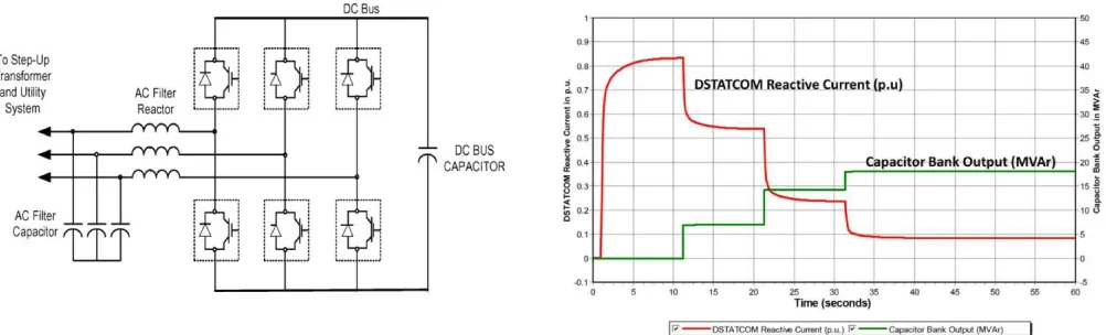
Fig:1: Schematic diagram of one device in a DSTATCOM system. Fig:2: Simulation plot of the DSTATCOM control and coordination with switchable capacitor banks (red DSTATCOM output; green capacitor bank output).
Steady state output of the DSTATCOM can reduce the operating losses of the DSTATCOM and associated equipment, such as transformers, and, hence, prolong the life of the equipment. All of these potential benefits can be realized in the application of the SRR when operating in the -control mode. The combined control system slowly drives the DSTATCOM output toward a low target value within several minutes after a system change (that results in high VAr output of the DSTATCOM), while still observing required operating parameters.
The following sections focus on modeling the DSTATCOM master controller with the -control mode, the new control strategy, and algorithm for calculating the SRR operation constraints, implementation and simulations, and case studies.
II. MODELING OF NEW CONTROL STRATEGY AND ALGORITHM FOR THE CALCULATION OF OPERATION
CONSTRAINTS A. Explanation of the DSTATCOM
Fig. 1 shows a schematic diagram of one device in a DSTATCOM system which uses IGBT-based dc-to-ac in-verters. The inverter creates an output ac voltage that is controlled using pulse width modulation technologies to pro-duce either leading (capacitive) or lagging (inductive) variable
Reactive current (or ) into the utility system. The inverter-based DSTATCOM can maintain a constant current in or out of
the system during low or high voltages and thus, its reactive power is directly proportional to the system voltage This short-time capacitive or inductive rating provides significant dynamic reactive compensation to maintain system voltage stability during dynamic events [8].
The DSTATCOM can be configured to control and coordi-nate its output with slower reactive support elements, such as switchable capacitors or reactors for system voltage support. Such control and coordination for an engineering project have been discussed in [9]. For illustrative purposes, a sample sim-ulation is plotted in Fig. 2 to show the DSTATCOM reactive output (red line) versus time that starts with a small value and then increases very fast following a contingency event at 1 s, and then decreases to a new lower set point when three capacitor banks (green line) are switched in with a delay time of 10 s.
B. DSTATCOM Master Controller with the -Control Mode
Fig. 3 shows a modeling block diagram of the DSTATCOM master controller in the -control mode with the SRR (red lines) and interface to a transmission system where multiple renewable power plants are also connected. This figure represents an engineering application at a wind generation hub where the transmission operator usually requires a minimum impact on voltage and VAr flow caused by the variable wind generation. In the diagram, the DSTATCOM is configured to control the VAr flow at the point of interconnection (POI) of the renewable plants, which is a 230-kV bus in the transmission system miles away from the plant location. In this case, the VAr flows on the transfer paths of the transmission system may be controlled by substation-based DSTATCOM systems with similar control configurations.
930
©IJRASET: All Rights are Reserved
utilities require this target to be a very small value, that is, the VAr flow interchange with the system at the POI is controlled to be close to zero. Other utilities allow this target to be controlled within the VAr flow thresholds which are also settable and adjustable via SCADA by the system operator. In the implementation of this type of control method, the DSTATCOM master control system requires as input:
1) local measurements such as P, Q, V, and I, etc.;
2) remote measurements of P, Q, V, and I through communication systems;
Fig: 3: DSTATCOM master controller, slow reset regulator, and interface with a transmission system.
3) The calculation of remote parameters using local measurements in a technique that is called line drop compensation (LDC), when the remote measurements are unavailable.
The DSTATCOM master controller is based on a proportional-plus-integral (PI) controller with the operating limits. This DSTATCOM master controller is also configured to control and coordinate the inverter output with switched shunt de-vices (SSDs). These devices include mechanically switched re-actors (MSRs) located in the same plant location or mechanically controlled capacitors in a remote location (e.g., 230-kV MSC in Fig. 3) for system reactive power and voltage support.
C. New Control Method and Modeling
The new control strategy applies the SRR to slowly bias the VAr set point of the DSTATCOM operating in the -control mode to maintain the steady-state output of the DSTATCOM
Within a predefined target bandwidth (i.e., in Fig. 3) This new feature is different when compared to standard V-control-based SRR [1]–[3] that forces the output to zero independent of other observations. This new control strategy only allows the output to move toward zero within the operating range of the VAr flow target level at the local or remote point. Other transmission system constraints or generation sources may also require the limitation of that VAr flow. The SRR addition allows the DSTATCOM to work within the allowable range by moving the operating output point toward a low target value. This can minimize the steady-state output of the equipment and associated operating losses and maximize the VAr reserve for dynamic events in the transmission system.
The -control-based SRR, as used in the new control strategy, is essentially a proportional-integral (PI) controller with varying
control or operation constraints ( , in Fig. 3) as determined or calculated by the allowable VAr
flow thresholds and the actual VAr flow at the remote point in the transmission system (e.g., the POI for a renewable resource hub). The output of this PI controller is added to the VAr set point of the DSTATCOM. From Fig. 3, the input to the DSTATCOM master controller is
Other Signals (1)
931
©IJRASET: All Rights are Reserved
is the actual VAr flow at the remote point in the transmission system (e.g., at the POI), is the output of the
SRR for biasing the VAr setpoint of the DSTATCOM, and other signals (which may include the system voltage and real power at the local or remote point or the status of the remote 230-kV MSC, etc.).
The tuning of this PI controller and calculation of its opera-tion constraints are important for SRR operation. In general, the PI controller parameters are tuned such that the SRR begins to regulate over a relatively long period of time after system dynamics (caused by faults, line trips, loss of renewable or conventional generation, etc.) have passed and the system has almost settled down to a new operating point. The operating constraints are determined and calculated based on the allowable VAr flow thresholds and the actual VAr flow at the remote point in the system.
D. New Algorithm for the Calculation of SRR Operation
The -control-based SRR operating constraints and in Fig. 3 are varying with, and calculated based on the
measurement of the actual VAr flow and the allowable VAr flow range at the selected target system location. In Fig. 3, the selected target system location is assumed to be the POI for the renewable power plants, which is a 230-kV bus in the transmission system miles away from the plant location. The calculation of the SRR operation constraints is as follows:
(2)
(3)
(4)
(5) IF
(6)
Where
1) and are upper and lower VAr flow limiting values at the POI;
2) is the actual VAr flow at the POI;
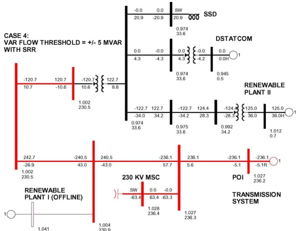
Fig: 4: Simulation system with the DSTATCOM-based RCS on the -control with SRR and renewable power plants. (The numbers in the figure represent bus voltages in per unit and kilovolts and branch power flows in megawatts and megavolt-amperes.) Fig: 5: DSTATCOM output response without with the slow reset regulator after a step change (Increase) in the setpoint (red
without the SRR; green with the SRR).
3) and are the differences between the upper or lower VAr flow tolerance and the actual VAr flow at
the POI;
932
©IJRASET: All Rights are Reserved
III. IMPLEMENTATION, SIMULATIONS, AND CASE STUDIES
A. Description of the Simulation System
Fig. 4 is a one-line diagram from the aforementioned simulator to show part of a real transmission system where an engineering project was installed including a DSTATCOM-based reactive compensation system (RCS) with SRR and two renew-able power plants which have a total capacity of approximately 550 MW. The RCS consists of the following major equipment:
1)one 15-MVAr DSTATCOM.
2)four 34.5-kV, 11-MVAr mechanically switched reactors [MSRs, collectively referred to as switched shunt devices (SSDs)].
3)two 230-kV, 60-MVAr mechanically switched capacitors (MSC).
The RCS is required to control the VAr flow at the POI (230-kV bus in the transmission system miles away from the plant location) within the thresholds set by the system operator via SCADA with varying output of renewable energy production or other changing system conditions. At the same time, the DSTATCOM operates at a low output (as possible in the steady-state condition) to maximize the VAr reserve for contingency events and to reduce equipment and associated operating losses. The SSD is controlled and switched by the DSTATCOM master controller as part of steady-state and dy-namic voltage and reactive support. The 230-kV MSC may be controlled by the DSTATCOM master control system or with an independent controller. The renewable power plants operate on an approximate unity power factor.
B. Response to a Step Change in VAr Set Point
The step change (increase or decrease) was applied in the set point of the DSTATCOM master controller, and the output of the DSTATCOM following the disturbance was monitored. The pre disturbance condition of the system is shown in Fig. 4 where the VAr flow at the POI is about 2.5 MVAr, and the DSTATCOM has a zero output.
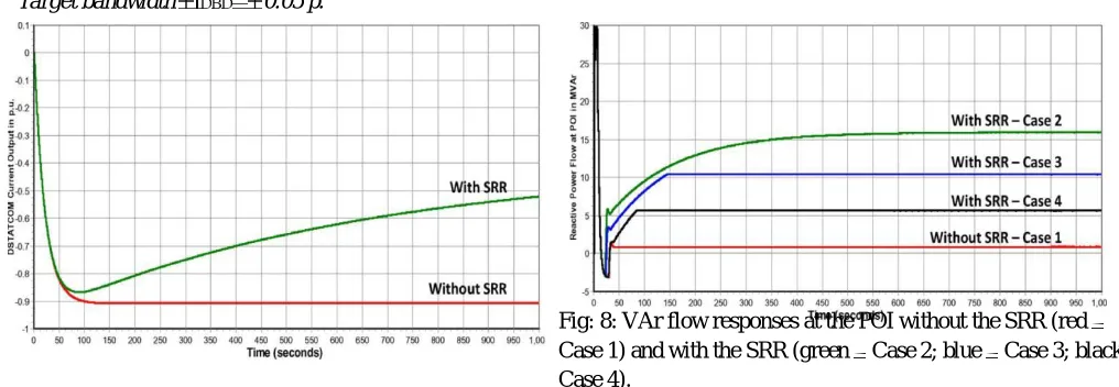
Figs. 5 and 6 show the simulation plots following the set-point step change. It is shown from the figures that the SRR is controlling the DSTATCOM output (green lines) to be within the target bandwidth 0.5 p.u. after the disturbance. This indicates that the SRR is functioning and slowly biasing the set point to meet the target bandwidth. Without the SRR, the DSTATCOM output (red lines) settles at approximately 0.9p.u. after the step change as expected. The change in the DSTATCOM output following the disturbance is being offset or balanced by other system VAr sources, since the SSD and the 230-kV MSC do not switch in this simulation.
C. Case Studies
In these studies, the allowable VAr flow thresholds at the POI were set to different values and the target bandwidth (i.e., in
Fig. 3) of the DSTATCOM was set to a small value so that the steady-state output of the DSTATCOM is controlled by the SRR to be close to the target value within the VAr flow thresholds and to maximize the dynamic VAr reserve for contingency events. The following cases, parameters, and disturbances were simulated.
[image:5.612.51.559.503.679.2]1) Target bandwidth 0.05 p.
Fig: 8: VAr flow responses at the POI without the SRR (red Case 1) and with the SRR (green Case 2; blue Case 3; black Case 4).
933
©IJRASET: All Rights are Reserved
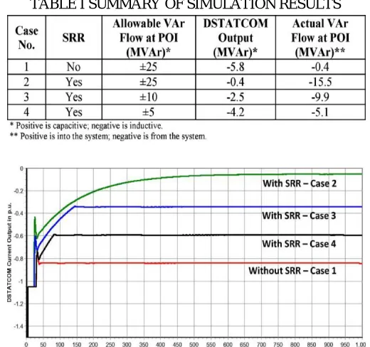
[image:6.612.176.436.80.324.2]TABLE I SUMMARY OF SIMULATION RESULTS
Fig: 7: DSTATCOM output responses without the SRR (red Case 1) and with the SRR (green Case 2; blue Case 3; black Case 4)
Allowable VAr flow thresholds at the POI:
a) 25 MVAr (without the SRR);
b) 25 MVAr (with the SRR);
c) 10 MVAr (with the SRR);
d) 5 MVAr (with the SRR).
2) Contingency: Loss of the Renewable Power Plant I and one 230-kV capacitor bank to simulate variable renewable gen-eration production.
3) SRR operation constraints ( and in Fig. 3) are calculated according to (2)–(7) in Section II-D.
[image:6.612.168.435.518.705.2]In all of these cases, the SSD was set to operate as necessary during dynamics following the contingency. The remaining 230-kV capacitor bank does not switch following the contingency.
Table I summarizes the results of the case studies. The higher the allowable VAr flow thresholds at the POI, the lower the
Fig: 9: Post contingency power flow without the slow reset regulator (Case 1. allowable VAr flow thresholds at the 25
934
©IJRASET: All Rights are Reserved
Fig: 10: Post contingency power flow with the slow reset regulator (Case 2, allowable VAr flow thresholds at the 25 MVAr).
DSTATCOM output is adjusted by the SRR, which is func-tioning as expected. The details of post contingency power flows are shown in Figs. 7–12 and will be
935
[image:8.612.134.437.87.321.2]©IJRASET: All Rights are Reserved
Fig: 12: Post contingency power flow with the slow reset regulator (Case 4, allowable VAr flow thresholds at the 5 MVAr).
POI is 15.5 MVAr (Fig. 10). Thus, the benefit of using the allowable VAr flow thresholds is that the steady-state output of the DSTATCOM and its associated operating losses can be minimized, and the VAr reserve from the equipment can be maximized for dynamic events in the system.
When the actual VAr flow is at the threshold, the operation constraints of the SRR would be zero according to (2)–(7) in Section II-D. Thus, there is no regulation room for the SRR and it stops regulation, and the DSTATCOM output settles at the value corresponding to the VAr flow threshold at the POI. This is shown in Cases 3 and 4 where the DSTATCOM settles at 2.5 MVAr and 4.2 MVAr, respectively, and the VAr flow at the POI 9.9 MVAr and 5.1 MVAr, respectively (Figs. 11 and 12). As long as the VAR flow thresholds are nonzero, the benefit of the SRR regulation can be seen because the DSTATCOM does not need to operate at the full capacitive or inductive output, a condition with little dynamic VAr reserve that usually causes the highest operating losses.
These case studies further show that the -control-based SRR is functioning properly as expected under either the nonlimiting or limiting VAr flow condition at the POI.
Fig. 7 shows the DSTATCOM outputs without the SRR (red Case 1) and with the SRR (green Case 2); (blue Case 3); (black Case 4). Fig. 8 shows the VAr flow responses at the POI without the SRR (red Case 1) and with the SRR (green Case 2); (blue Case 3); (black Case 4), which are following the changes in the DSTATCOM output in each case while honoring the VAr flow thresholds at the POI
Without the SRR, the DSTATCOM output settles at approx-imately 0.77 p.u. (Fig. 7) or absorbs 5.8 MVAr and the VAr flow at the POI settles at 0.4 MVAr (Fig. 9).
With the SRR in operation, the DSTATCOM output is brought within a 0.05-p.u. bandwidth or 0.4 MVAr (Fig. 10) when the actual VAr flow at the POI is within the VAr flow thresholds. This is shown in Case 2 where the VAr flow thresh-olds are set to 25 MVAr and the actual VAr flow at the
IV. ARTIFICIAL NEURAL NETWORK
936
[image:9.612.169.427.89.245.2]©IJRASET: All Rights are Reserved
Fig 13. Neural network as a black-box featuring the nonlinear
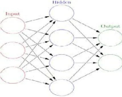
Relationship between the multivariate input variables and multi-variants responses Neural networks (also referred to as connectionist systems) are a computational approach, which is based on a large collection of neural units (AKA artificial neurons), loosely modeling the way a biological brain solves
problems with large clusters of biological neurons connected by axons. Each neural unit is connected with many others, and links can be enforcing or inhibitory in their effect on the activation state of connected neural units. Each individual neural unit may have a summation function which combines the values of all its inputs together
Fig:14: An artificial neural network is an interconnected group of nodes.
The goal of the neural network is to solve problems in the same way that the human brain would, although several neural networks are more abstract. Modern neural network projects typically work with a few thousand to a few million neural units and millions of connections, which is still several orders of magnitude less complex than the human brain and closer to the computing power of a worm.
Applications
1) Multi level inverters are applied to transmission & Distribution systems.
2) Multi level inverters are applied to STATCOM to Improve stability.
V. CONCLUSION
[image:9.612.179.393.344.514.2]937
©IJRASET: All Rights are Reserved
detect complex nonlinear relationships between dependent and independent variables; it has ability to detect all possible interactions between predictor variables; etc. The proposed state-space model is validated by comparing with simulation results for a comprehensive switched model.
An engineering project which includes a DSTATCOM-based reactive compensation system and multiple renewable power plants where the -control mode was used to regulate the transmission VAr flow at a remote point in the transmission system. The model testing and case studies showed that the new control strategy and algorithm are functioning properly as expected. The SRR slowly drives the output of the DSTATCOM with the -control mode toward a low target value within several minutes after a system change that results in high VAr output of the equipment. The DSTATCOM has been applied to several engineering projects that required 92% to 100% of the equipment MVAr rating for such dynamic VAr reserve.
REFERENCES
[1] Rajiv K. Varma, Senior Member, IEEE, Shah Arifur Rahman, Member, IEEE, and Tim Vanderheide, Member, IEEE,"New Control of PV Solar Farm as STATCOM (PV-STATCOM) for Increasing Grid PowerTransmission Limits During Night and Day",IEEE TRANSACTIONS ON POWER DELIVERY, VOL. 30, NO. 2, APRIL 2015.
[2] N. G. Hingorani and L. Gyugyi, Understanding FACTS: Concepts and Technology of Flexible AC Transmission Systems. Piscataway, NJ, USA: IEEE, 2000. [3] WECC Static VAr Compensator Task Force, “Generic static VAr system models for the Western Electricity Coordinating Council,” Rep. no. 4/18/11, Apr. 18,
2011.
[4] Y. Xu and F. Li, “Adaptive PI control of STATCOM for voltage reg-ulation,” IEEE Trans. Power Del., vol. 29, no. 3, pp. 1002–1011, Jun. 2014.
[5] S. Kincic, X. (G.) T. Wan, D. T. McGillis, A. Chandra, B.-T. Ooi, F. D. Galiana, and G. Joos, “Voltage support by distributed Static VAr Systems (SVS),” IEEE Trans. Power Del., vol. 20, no. 2, pt. 2, pp. 1541–1549, Apr. 2005
[6] Jain, K. Joshi, A. Behal, and N. Mohan, “Voltage regulation with STATCOMs: Modeling, control and results,” IEEE Trans. Power Del., vol. 21, no. 2, pp. 726–735, Apr. 2006.
[7] D. Soto and R. Pena, “Nonlinear control strategies for cascaded multilevel STATCOMs,” IEEE Trans. Power Del., vol. 19, no. 4, pp. 1919–1927, Oct. 2004. [8] C. Hochgraf and R. H. Lasseter, “STATCOM controls for operation with unbalanced voltage,” IEEE Trans. Power Del., vol. 13, no. 2, pp. 538–544, Apr. 1998. [9] A. H. Norouzi and A. M. Sharaf, “Two control schemes to enhance the dynamic performance of the STATCOM and SSSC,” IEEE Trans. Power Del., vol. 20,
no. 1, pp. 435–442, Jan. 2005.
[10] V. Spitsa, A. Alexandrovitz, and E. Zeheb, “Design of a robust state feedback controller for a STATCOM using a zero set concept,” IEEE Trans. Power Del. , vol. 25, no. 1, pp. 456–467, Jan. 2010.
[11] W. Chen, A.Q. Huang, C. Li, G. Wang, and W. Gu, Analysis and comparison of medium voltage high power DC/DC converters for offshore wind energy systems,‖ IEEE Trans. Power Electron., vol. 28, no. 4, pp. 2014– 2023, Apr. 2013.
Author Details
G. Srinivasarao Associate Professor
Department of Electrical and Electronics Engineering, MITK, Khammam, T.S - 507163, India.