Optimal Real-Time Predictive Control for
Maximising the Power-Take-Off Efficiency of
the WaveRAM Wave Energy Converter
Author:
Christopher Daniel SIGNORELLI
Supervisor:
Prof. Biswajit BASU
Thesis submitted to the University of Dublin, Trinity College for the degree of
Doctor of Philosophy
iii
Declaration of Authorship
I, Christopher Daniel SIGNORELLI, declare that this thesis titled, “Optimal Real-Time Predic-tive Control for Maximising the Power-Take-Off Efficiency of the WaveRAM Wave Energy Converter” has not been submitted as an exercise for a degree at this or any other university and it is entirely my own work.
I agree to deposit this thesis in the University’s open access institutional repository or allow the library to do so on my behalf, subject to Irish Copyright Legislation and Trinity College Library conditions of use and acknowledgement.
Signed:
v
Abstract
The aim of this thesis is to develop a control strategy for optimising the power-take-off (PTO) efficiency of the newly developed WaveRAM (WRAM) wave energy converter. The three main research streams established to satisfy these requirements have been: 1) the de-velopment of a wave-to-wire numerical model of the WRAM and its PTO system; 2) the implementation of a real-time model predictive control (RT MPC) algorithm; and 3) the con-struction of a laboratory test rig, capable of emulating the behaviour of a sea-going device. Given that the WRAM is intended for deployment at sea in the near future, the control al-gorithm must be capable of operating in real-time. This has been the primary motivation of the second research stream, where portions of the model created in the first stream were used as the controlled plant. In order to verify the algorithm’s performance prior to sea-deployment, the laboratory test facility from the third stream ensures that the algorithm can operate successfully within practical constraints.
With regards to the first research stream, many parts of the numerical model for WRAM were derived based on well-accepted fundamental physics in the literature. For the subsys-tems where the fundamental physics were not well-known, or parameters were captured more accurately with physical equipment, new models were derived. The well-accepted components include the WRAM’s hydrodynamics, air chamber pneumatics and the tur-bine’s characteristics. The unknown components were within the turbo-generator system, where not all parameter values were available at design. As such, system identification was adopted to identify the unknown values from laboratory experiments. Results of the system identification process showed a closeness-of-fit of 96% between the experimental re-sults and theoretical model. The WRAM’s wave-to-wire model was then completed, with the turbine-to-wire portion being controlled by the RT MPC algorithm.
faster than what has been reported in the literature for wave energy applications. The high speed of the algorithm makes it possible for real-time implementation on standard industrial control systems. Another component of the research was to investigate the performance of alternative cost functions in the optimal control problem. Results showed that care is needed in choosing an appropriate cost function, depending on the type of wave energy converter being controlled. Further questions were raised as to whether the closed-form method of RT MPC is appropriate for both cost functions used.
Lastly, in the third stream, an emulation platform has been produced, allowing for ad-vanced control algorithms to be tested on realistic hardware, prior to implementation at sea. The platform has been integrated into an existing real-time hybrid test (RTHT) facility, such that aspects of the WRAM model, not implemented on the emulator platform, can be simu-lated within a real-time feedback loop. The RTHT approach helps bridge the gap between academic and industrial partners, where advanced theoretical algorithms can be tested in a safe laboratory environment. Industrial partners can then draw confidence in the technol-ogy before bearing the financial risk of failure at sea. The emulation platform developed in this research is the first of its kind, as it is capable of emulating the bidirectional, irregular flow conditions typical of oscillating water columns. Furthermore, it can do so within a RTHT framework. Other similar test facilities offer only a subset of these features.
vii
Acknowledgements
Prof. Biswajit Basu. I would like to sincerely thank my supervisor, Professor Biswajit Basu, both on a personal and professional level for granting me the opportunity to under-take this Ph.D. In addition to his mathematical expertise, I’m grateful for his flexibility in allowing me to work at my own pace, which during some periods would have appeared much more industrial than academic when developing the elaborate test rig. This has al-lowed a very well developed test rig to be built with the potential for significant future re-search that links academic rere-search and off-the-shelf industrial technology. Finally I would like to acknowledge his financial support in the early stages of the Ph.D.
William Dick. Special thanks also to William Dick, founder of Swirl Generators Limited (SGL), who was the key inspiration for taking on the Ph.D. As with most opportunities the timing was perfect, given that at the time I was eager to take on work that was more aca-demically stimulating. William has also been very flexible and generous in granting me the time to focus on my research when needed. Since late 2015, his contribution through En-terprise Ireland’s Innovation Partnership Programme (IPP) and subsequently directly from SGL, has provided the financial support to sustain myself and my family while completing the Ph.D. I look forward to further applying what I have learned throughout the Ph.D. to William’s WaveRAM invention.
University College Cork, Electrical & Electronic Engineering. Thanks to Prof. William Wright and his team at the Electrical & Electronic Engineering department in UCC for loan-ing their replica turbine for use on the test rig. The help came when time was quickly run-ning out on the IPP project, however thanks to speedy refurbishment and delivery, project delays were avoided and significant value has been added to the research outcomes.
Civil Engineering Technical Team. The outstanding efforts of Civil Engineering’s tech-nicians deserve special mention, especially Dr. Kevin Ryan and Dave McAulay. In addition to their willingness to assist under constantly strained resources, and needless to say their technical expertise, their openness in bouncing implementation ideas back and forth was greatly welcomed. This particularly helped the creative process in the early design stages and some retrofitting towards the end.
ix
Contents
Declaration of Authorship iii
Abstract v
Acknowledgements vii
List of Figures xiii
List of Tables xvii
1 Introduction 1
1.1 Motivation . . . 1
1.2 Research Aims . . . 3
1.3 Research Questions . . . 3
1.4 Research Objectives . . . 3
1.5 Research Streams . . . 4
1.6 Chapter Outline . . . 6
1.7 Novelty of the Research . . . 8
2 Literature Review 9 2.1 WEC Control Strategies . . . 9
2.1.1 Optimal Control . . . 10
2.1.2 Non-Causal Discrete Control . . . 10
2.1.3 Causal Reactive Control . . . 12
2.1.4 Causal Discrete Control . . . 13
2.1.5 Other Control Strategies . . . 14
2.2 Control Challenges for Sea-Going WECs . . . 19
2.2.1 Model Sensitivity . . . 19
2.2.2 PTO Constraints and Efficiencies . . . 20
2.2.3 Real-Time Capability . . . 20
2.2.4 Suitability for OWCs . . . 21
2.2.5 Multiple Bodies . . . 21
2.2.6 Algorithm Complexity . . . 21
3 Real-Time MPC Background 23 3.1 Traditional MPC . . . 24
3.1.1 Plant Model . . . 24
3.1.2 Prediction Window . . . 25
3.1.3 Unconstrained Optimal Control . . . 27
3.1.4 Closed-Loop Feedback . . . 27
3.1.5 State Estimation . . . 28
3.1.6 Constrained Control . . . 29
3.2 MPC using Laguerre Functions . . . 31
3.2.1 Main Concept . . . 31
3.2.2 State and Output Prediction . . . 33
3.2.3 Minimising the Cost Function . . . 33
3.2.4 Receding Horizon Control and Closed-Loop Stability . . . 35
3.2.5 Laguerre Tuning Parameters . . . 35
3.2.6 Closed-Form Constrained Control . . . 36
3.2.7 Justification of Laguerre Functions in the Current Research . . . 39
4 Modelling of the WRAM 41 4.1 WRAM Concept . . . 41
4.2 Broad Description of the Numerical Model . . . 42
4.3 Wave-to-Turbine Model . . . 43
4.3.1 Mechanical Oscillator . . . 43
xi
4.3.3 Water Column Representation . . . 45
4.3.4 Hydrodynamic Coefficients . . . 46
4.3.5 Boundary Element Method . . . 46
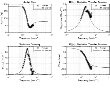
4.3.6 Approximation of the Radiation Damping . . . 46
4.3.7 Excitation Forces . . . 48
4.3.8 Wave-to-Relative Motion . . . 49
4.3.9 Air Chamber Pneumatics . . . 51
4.3.10 Turbine Torque and PTO Force . . . 53
4.4 Sea States . . . 58
4.5 Turbine-to-Wire Model . . . 61
4.5.1 Generator . . . 61
4.5.2 Fundamental Generator Model . . . 62
4.5.3 Drive Loops . . . 65
4.5.4 Current Loop . . . 66
4.5.5 Velocity Loop . . . 69
4.6 System Identification . . . 71
4.6.1 Model Parametrisation . . . 71
4.6.2 System Identification Experiments . . . 73
4.6.3 Grey-Box System Identification . . . 74
4.6.4 Reduced Order Discrete Model . . . 74
4.7 NMSS Plant Formulation . . . 75
4.7.1 MIMO Plant Model . . . 75
4.7.2 Matrix Fraction Description . . . 75
4.7.3 NMSS Formulation . . . 78
5 WRAM Emulator 81 5.1 Concept . . . 81
5.2 Architecture . . . 81
5.3 Emulator Subsystems . . . 83
5.3.1 Emulated OWC Air Flow . . . 83
5.3.3 PTO Assembly . . . 86
5.3.4 Instrumentation . . . 87
5.3.5 Communication . . . 89
5.3.6 Data Logging and Synchronisation . . . 89
5.3.7 Power Dissipation . . . 89
5.4 Calibration . . . 89
5.4.1 Pneumatic Sensors . . . 90
5.4.2 Paddle Rotation to Actuator Stroke . . . 92
5.4.3 Servo-Generator Tuning . . . 92
5.4.4 Data Synchronisation . . . 95
5.4.5 Open Loop Turbine Tests . . . 95
5.5 RT Hybrid Testing Background . . . 98
5.5.1 Concept . . . 98
5.5.2 Historical Development . . . 98
5.5.3 Applications . . . 99
5.6 RT Hybrid Test Rig . . . 99
5.6.1 Test Rig Architecture . . . 99
5.6.2 MTS Control System . . . 99
5.6.3 RT Hybrid Loop . . . 102
6 Control Implementation 105 6.1 Distinction between WRAM Absorber and PTO Control . . . 105
6.1.1 WRAM Absorber Control . . . 105
6.1.2 PTO Control . . . 107
6.2 RT MPC of the Generator . . . 107
6.2.1 Alternative Cost Functions . . . 108
6.2.2 Implementation of Closed-Form Constrained Control . . . 110
7 Results and Discussion 113 7.1 WRAM Uncontrolled Simulations . . . 113
xiii
7.3 Generator Model . . . 117
7.4 Real-Time MPC . . . 119
7.4.1 Identification of Laguerre Parameters . . . 119
7.4.2 Sensitivity Analysis of Tuning Parameters . . . 120
7.4.3 RT MPC Performance Assessment . . . 125
7.4.4 Real-Time Execution Speed . . . 129
7.4.5 Alternative Power Maximisation Cost Function . . . 129
8 Conclusions 137 8.1 Summary of the Research . . . 137
8.2 Main Findings . . . 139
8.3 Research Questions . . . 142
8.4 Recommendations for Further Work . . . 144
8.5 Concluding Remarks . . . 146
Appendix A WRAM Emulation Platform Mechanical Design 147
Appendix B WRAM Emulation Platform Electrical Design 163
xv
List of Figures
1.1 Research Streams . . . 5
4.1 WRAM Illustration . . . 42
4.2 WRAM Schematic and Free-Body Diagrams . . . 44
4.3 Nemoh Mesh for WRAM Body . . . 47
4.4 Nemoh Mesh for Water Column . . . 48
4.5 Flow vs Pressure Coefficient . . . 56
4.6 Power vs Flow Coefficient . . . 56
4.7 Bretschneider Spectrum . . . 61
4.8 Kollmorgen AKM23F Servo-Generator . . . 63
4.9 MIMO Generator Block . . . 64
4.10 Kollmorgen AKD Servo-Drive . . . 65
4.11 Actual PD-Control Loop for Servo-Drive . . . 65
4.12 Simplified Equivalent PI-Control Loop . . . 66
4.13 Current Loop with MIMO Generator . . . 66
4.14 Current Loop MIMO Block . . . 67
4.15 Classical Feedback Loop Model . . . 67
4.16 Velocity Loop Block Diagram . . . 69
4.17 System Identification of the Generator Parameters . . . 73
5.1 WRAM Emulation Platform . . . 82
5.2 WRAM Emulator Platform Architecture . . . 83
5.3 3D Solid Model of Blast Box . . . 84
5.4 Paddle Actuation Arrangement . . . 85
5.6 PTO Assembly Nacelle . . . 86
5.7 Instrumentation Network for the Emulation Platform . . . 87
5.8 Control and Instrumentation Panel . . . 88
5.9 Sensors Installed on the Emulation Platform . . . 90
5.10 Paddle Calibration Curves . . . 93
5.11 Generic PID Control Loop . . . 93
5.12 Cross Correlation of Synchronisation Signals . . . 95
5.13 Synchronised Pressure Signals . . . 96
5.14 Uncontrolled Turbine Velocity due to Air Flow . . . 97
5.15 Controlled Turbine Velocity with Air Flow . . . 97
5.16 Computing Nodes on the RTHT Network . . . 100
5.17 Test PC User Interface . . . 102
5.18 Real-Time Hybrid Loop Diagram . . . 103
7.1 WRAM Relative Velocity and Turbine Torque - Uncontrolled . . . 113
7.2 WRAM Turbine Torque and PTO Force - Zero Crossings . . . 114
7.3 Hydrodynamic Radiation Transfer Function Approximation 33 . . . 115
7.4 Hydrodynamic Radiation Transfer Function Approximation 39 . . . 115
7.5 Hydrodynamic Radiation Transfer Function Approximation 93 . . . 116
7.6 Hydrodynamic Radiation Transfer Function Approximation 99 . . . 116
7.7 Excitation Force Transfer Function Approximations . . . 117
7.8 MIMO Generator Velocity Responses . . . 118
7.9 MIMO Generator Torque Responses . . . 118
7.10 Orthonormality versusaandN . . . 121
7.11 Power versusaandN . . . 123
7.12 Power versusNandNp . . . 124
7.13 Variance of Closed-Loop Poles . . . 125
7.14 RT MPC Generator Performance - Case 1 . . . 126
7.15 RT MPC Control Performance - Case 1 . . . 128
7.16 RT MPC Control Saturation - Case 1 . . . 129
xvii
7.18 RT MPC Control Performance - Case 2 . . . 131
7.19 Closed-Loop Poles of Controller - Case 1 . . . 132
7.20 Closed-Loop Poles of Controller - Case 2 . . . 132
7.21 Real-Time Execution Speed - Case 1 . . . 133
7.22 Real-Time Execution Speed - Case 2 . . . 133
7.23 RT MPC Performance with ‘Power Maximisation’ - Case 3 . . . 134
7.24 RT MPC Performance with ‘Power Maximisation’ - Case 4 . . . 135
xix
List of Tables
4.1 Identified Parameters of the MIMO Generator . . . 74
6.1 Implementation Steps for Closed-Form Constrained Control . . . 111
7.1 Correlation Coefficients for Laguerre Network Tuning Parameters . . . 120 7.2 Correlation between Tuning Parameters and Performance withNp =30 . . . 122
7.3 Correlation between Tuning Parameters and Performance withrw=1 . . . . 124
xxi
List of Abbreviations
BEM BoundaryElementMethod BS BretSchneider
CCW CounterClockWise CW ClockWise
cRIO CompactReconfigurableInputOutput (controller) DAQ DataAcQuisition
DLQR DiscreteLinearQuadraticRegulator DoF DegreeofFreedom
FD FrequencyDomain
FDI FrequencyDomainIdentification FPGA FieldProgrammableGateArray FSS Full-ScaleSpan
FTC Fault-TolerantControl
GPC GeneralisedPredictiveControl HIL HardwareIn (the)Loop
HRCF Half-RangeChebyshevFourier IO InputOutput
IP IntellectualProperty LCOE LevelisedCostOfEnergy LMFD LeftMatrixFractionDescription LQR LinearQuadraticRregulator LTI LinearTime-Invariant LUT LookUpTable
MPC ModelPredictiveControl MTS MTS(Systems Corporation) NLP NonLinearProgram
NMSS Non-MinimalStateSpace
NRMSE NormalisedRoot-Mean-SquaredError OWC OscillatingWaterColumn
P2P Peer-2-Peer
PI Proportional-Integral
PID Proportional-Integral-Derivative PLC ProgrammableLogicController PMP Pontryagin’sMaximumPrinciple PTO Power-Take-Off
QP QuadraticProgramming
RHPSC RecedingHorizonPseudospectral (optimal)Control RL ReinforcementLearning
RMS Root-Mean-Squared
RT MPC Real-TimeModelPredictiveControl RTHT Real-TimeHybridTest
SCFM StandardCubicFeet (per)Minute
SCRAMNET SharedCommonRandomAccessMemoryNETwork SISO Single-InputSingle-Output
STS StructuralTestSystem
TD TimeDomain
TPMLG TubularPermanentMagnetLinearGenerator WEC WaveEnergyConverter
xxiii
List of Symbols
Symbol Unit Description
a Laguerre network pole
a∞33 kg Added mass at infinite frequency for 3-3 coupling
a∞39 kg Added mass at infinite frequency for 3-9 coupling
a∞93 kg Added mass at infinite frequency for 9-3 coupling
a∞99 kg Added mass at infinite frequency for 9-9 coupling A Augmented state matrix forAm
A33 State matrix for the state space approximation of frad33(t) A39 State matrix for the state space approximation of frad39(t) A93 State matrix for the state space approximation of frad93(t) A99 State matrix for the state space approximation of frad99(t) Ac State matrix for continuous wave-to-relative motion model
Ad State matrix for discrete wave-to-relative motion model
Ag State matrix for MIMO generator model
Am State matrix for a generic LTI model
AΩ State matrix for non-augmented NMSS MIMO generator model ˆ
AΩ State matrix for augmented NMSS MIMO generator model
bt N m s Generator viscous friction constant (rotor and turbine)
B(t) psi Barometric pressure
B Augmented input matrix forBm
Bc Input matrix for continuous wave-to-relative motion model
Bd Input matrix for discrete wave-to-relative motion model
Bg Input matrix for MIMO generator model
Bm Input matrix for a generic LTI model
BΩ Input matrix for non-augmented NMSS MIMO generator model ˆ
BΩ Input matrix for augmented NMSS MIMO generator model
c3 N m−1 Hydrostatic restoring coefficient of WRAM body
c9 N m−1 Hydrostatic restoring coefficient of water column
ci ithLaguerre coefficient
C Augmented output matrix forCm
C33 Output matrix for the state space approximation of frad33(t) C39 Output matrix for the state space approximation of frad39(t) C93 Output matrix for the state space approximation of frad93(t) C99 Output matrix for the state space approximation of frad99(t) CB N m−1 Hydrostatic restoring coefficient matrix
Cc Output matrix for continuous wave-to-relative motion model
Cd Output matrix for discrete wave-to-relative motion model
Cg Output matrix for MIMO generator model
Cm Output matrix for a generic LTI model
CΩ Output matrix for non-augmented NMSS MIMO generator model ˆ
CΩ Output matrix for augmented NMSS MIMO generator model
di inches Internal duct diameter
dP(t) inchesH2O Differential pressure
D(s) Generic feedback model disturbance signal
Dt m Turbine rotor diameter
Dc Feedthrough matrix for continuous wave-to-relative motion model
Dd Feedthrough matrix for discrete wave-to-relative motion model
Dm(z) Partial LMFD decomposition ofGm(z)
e∆(t) Error between displacement setpoint and output for generic loop
xxv
E(t) V Generator winding voltage Eλ Equality constraint matrix
f Hz Frequency of sea state spectra
fc(t) N m−1 Generic excitation force impulse response function
fe(t) N Excitation force on a general body
fe3(t) N Excitation force on WRAM body
fe9(t) N Excitation force on water column
fPTO(t) N PTO force
frad33(t) N Radiation damping force for 3-3 coupling
frad39(t) N Radiation damping force for 3-9 coupling
frad93(t) N Radiation damping force for 9-3 coupling
frad99(t) N Radiation damping force for 9-9 coupling
F State matrix block for MPC
Frad(t) N Radiation damping forces for the wave-to-relative motion model
Fc(ω) N m−1 FD excitation force coefficient
Fei(ω) i
thfrequency response function component of the excitation force ∠Fei(ω) rad Phase ofFei(ω)
|Fei(ω)| N m−1 MagnitudeFei(ω)
Fi Coefficients of like-orders fromDm(z)
Fλ Equality constraint vector
G(s) Generic feedback model open-loop transfer function
Gdrive(s) Servo-drive transfer function including generator
Gg(s) MIMO generator transfer function
Gg11(s) SISO transfer function relatingTtandΩt
Gg12(s) SISO transfer function relatingEandΩt
Gg21(s) SISO transfer function relatingTtandI
Gg22(s) SISO transfer function relatingEandI Gi(s) MIMO current loop transfer function
Gi12(s) SISO transfer function relating ISP andΩt
Gi22(s) SISO transfer function relatingISPandI Gm(z) Generic second order discrete model
Gpd(s) Displacement loop PD-gains
Gpi(s) Equivalent velocity loop PI-gains
GΩ(s) MIMO velocity loop transfer function ˆ
GΩ(s) Parametrised version ofGΩ(s)
ˆ
GΩd(z) Discretised version of ˆGΩ(s)
H(k) Generic discrete impulse response function
H(s) Generic feedback model feedback transfer function Hi Coefficients of like-orders fromNm(z)
Hp m Paddle height
Hs m Significant waveheight
I(t) A Generator current
ISP(t) A Setpoint current
J Cost function
Jc Cost function for use with equality constraints
JP Cost function for direct power maximisation
JSP Cost function for setpoint tracking
Jt kg m2 Generator moment of inertia (rotor and turbine)
k Discrete time iteration number
K Pitot tube coefficient
kd∆ D-gain for generic displacement loop
kdν D-gain for generic velocity loop
Kdac Digital to analog gain
ki∆ I-gain for generic displacement loop
kiν I-gain for generic velocity loop
KiΩ I-gain for the velocity loop
Kpi Current loop P-gain
kp∆ P-gain for generic displacement loop
xxvii
KpΩ P-gain for the velocity loop
Ka A V−1 Servo-drive input signal gain
Ke V s rad−1 Generator electromotive force constant
Kmpc State feedback control gain vector
Kob Observer gain matrix
Kt N m A−1 Generator torque constant
Ky Setpoint gain within∆U(k)
KΩ Angular velocity scaling factor
L H Generator electric inductance
L(k) Vector of discrete time Laguerre functions at time instantk L33(t) N m s−1 Radiation damping impulse response function for 3-3 coupling
L39(t) N m s−1 Radiation damping impulse response function for 3-9 coupling
L93(t) N m s−1 Radiation damping impulse response function for 9-3 coupling
L99(t) N m s−1 Radiation damping impulse response function for 9-9 coupling
m3 kg Mass of WRAM body
m9 kg Mass of water column
mn m2Hzn−1 nthspectral moment
˙
mt(t) kg s−1 Turbine mass flow rate
M kg Mass matrix for the continuous wave-to-relative motion model Mc Inequality constraint matrix
Mcact Inequality constraint matrix with active constraints only
N Number of Laguerre functions (network order)
Nc Control horizon length
Nf Number of frequencies in sea state spectra
Np Prediction window length
Nm(z) Partial LMFD decomposition ofGm(z)
p(t) Pa Absolute chamber pressure
p∗(t) Dimensionless chamber pressure
pat(t) Pa Atmospheric pressure
pmin Pa Pressure lower range limit
pout(t) Pa Measured pressure
P(t) psig Static line pressure
Pg(t) W Generator power
Pt(t) W Turbine power
PWEC(t) W WEC absorber power
Q Quadratic optimisation matrix in RT MPC cost function QP Quadratic optimisation matrix for direct power maximisation
Qpad m3s−1 Volumetric flow swept by paddle
Qrel m3s−1 Volumetric flow from WRAM model
Qsc f m SCFM Volumetric flow at Pitot tube
QSP Quadratic optimisation matrix for setpoint tracking
r m Paddle radial width
rs Setpoint amplitude at beginning of prediction window
rw Control action tuning parameter amplitude
R Ω Generator electric resistance
R(s) Generic feedback model setpoint signal
R Control action tuning matrix
RL Control action tuning matrix in RT MPC cost function
Rs Setpoint signal over prediction window
s Complex variable for FD transfer functions
S(f) m2Hz−1 Spectral density
S(ω) m2s rad−1 Spectral density
Ss Specific gravity at 60oF
T(t) oF Temperature
Te s Energy period
Tg(t) N m Generator torque
Tp s Peak period
Ts s Sample period for discretising the wave-to-relative motion model
xxix
Tz s Zero-crossing period
u(k) Discrete control signal for a generic SISO LTI model
u∆(t) Control output variable for generic displacement loop
uν(t) Control output variable for generic velocity loop
Umax Upper constraint limits on the control signal Umin Lower constraint limits on the control signal Uc(t) N Wave-to-relative motion continuous model input
Ud(k) N Wave-to-relative motion discrete model input
Ug(t) MIMO generator inputs
Ui(t) Current loop inputs
Um(k) Inputs forGm(z)
UΩ(k) Inputs for non-augmented NMSS MIMO generator model UΩ(s) Velocity loop inputs toGg(s)
∆Uˆ
Ω Input for augmented NMSS MIMO generator model
∆U(k) Differential control signal vector over control horizon
∆Umax Upper constraint limits on the differential control signal
∆Umin Lower constraint limits on the differential control signal
∆Uopt(k) Optimal differential control vector over the control horizon ∆u(k) Differential control signal foru(k)
V0 m3 Chamber volume at rest
Vc(t) m3 Chamber volume
Vout(t) V Measured pressure sensor voltage
Vpad(t) m3 Volume of a cylindrical sector swept by the paddle
Vs V Supply voltage for pressure sensors
xri ithstate of the radiation damping approximations
X(k) Augmented state variable forXm
Xc(t) State variable for continuous wave-to-relative motion model
Xd(k) State variable for discrete wave-to-relative motion model
Xg(t) MIMO generator state variable
ˆ
Xm(k) Estimated state variable forXm(k)
XP(k) Augmented state variable for direct power maximisation
XSP(k) Augmented state variable for setpoint tracking
XΩ(k) State variable for non-augmented NMSS MIMO generator model
∆Xm(k) Differential state variable forXm(k)
∆Xˆ
Ω(k) Differential state variable for ˆXΩ(k)
y(k) Discrete output signal for a generic SISO LTI model
y33(t) State space approximation of frad33(t)
y39(t) State space approximation of frad39(t)
y93(t) State space approximation of frad93(t)
y99(t) State space approximation of frad99(t)
Y(s) Generic feedback model output signal Y(k) Outputs over prediction window
Yc(t) Outputs for continuous wave-to-relative motion model
Yd(k) Outputs for discrete wave-to-relative motion model
Yg(t) MIMO generator outputs
Yi(s) Current loop outputs fromGi(s)
Ym(k) Output vector forGm(z)
Ymax Upper constraint limits on the output Ymin Lower constraint limits on the output
YΩ(k) Output vector for non-augmented NMSS MIMO generator model YΩ(s) Velocity loop outputs fromGΩ(s)
ˆ
YΩ(k) Output for augmented NMSS MIMO generator model
z3(t) m Heave displacement of WRAM body
z9(t) m Heave displacement of water column
˙
zY m s−1 Velocity input to state space approximation of fradXY(t)
γa Specific heat ratio for air
γ Inequality constraint vector
γact Inequality constraint vector with active constraints only
xxxi
ζ(t) m Wave elevation
ζi m Wave amplitude of theithsea state spectral component
ηt Turbine efficiency
η Laguerre coefficient vector
ηopt Optimal Laguerre coefficient vector
ηoptP Optimal Laguerre coefficient vector for direct power maximisation
ηopt
SP Optimal Laguerre coefficient vector for setpoint tracking
θ(t) rad Output shaft displacement θr(t) rad Paddle angle of rotation
θSP(t) rad Setpoint shaft displacement
λe Closed-loop system eigenvalues
ξ Turbine hub-to-tip ratio
Πt Turbine dimensionless power coefficient
ρ(t) kg m−3 Chamber air density ρat(t) kg m−3 Atmospheric air density
ρin(t) kg m−3 Inlet density at stagnation conditions
φi rad Random phase of theith sea state spectral component
φ Discrete convolution sum for RT MPC formulation
Φt Turbine dimensionless flow coefficient Φ Current prediction matrix for MPC
Ψt Turbine dimensionless pressure coefficient
Ψ Linear Laguerre cost matrix
ΨP Linear Laguerre cost matrix for direct power maximisation ΨSP Linear Laguerre cost matrix for setpoint tracking
ω rad s−1 Angular frequency of sea state spectra
ωi rad s−1 Angular frequency of theithsea state spectral component
ωp rad s−1 Peak angular frequency of sea state spectra Ωt(t) rad s−1 Turbine angular velocity
Ω Quadratic Laguerre cost matrix
Ωrev(t) rev s−1 Output velocity ΩrevSP(t) rev s−
1 Setpoint velocity
xxxiii
1
Chapter 1
Introduction
1.1
Motivation
Maximising the power capture of wave energy converters (WEC) is crucial for reducing their levelised cost of energy (LCOE), which in turn contributes to economic viability. The control of wave energy devices has been extensively studied over the last several decades, however there is still a lack of convergence to a proven strategy or subset of strategies, suitable for deployment at sea. This is partly due to the lack of convergence towards a single WEC type, and partly due to the hesitation of wave energy developers to implement advanced control strategies.
The WEC under consideration in this research is the WRAM, fully described in Chap-ter 4. The fundamental physics of the WRAM are very similar to those of a floating point absorber with an oscillating water column (OWC). As such the control related issues are directly relevant to the WRAM. All WECs have several stages of power conversion from the wave-to-wire. In the case of OWC-like devices, the first controllable stage is the air plenum in the OWC chamber, where the pressure or volumetric flow rate are controlled. The next controllable stage is the turbine-generator set, where the turbine velocity or torque are con-trolled through the generator. It is important to control both of these stages, since both of their efficiencies can significantly affect the WEC’s overall power output. Furthermore, each stage needs to be controlled within practical engineering constraints, such as maximum torques, velocity and power ratings.
be challenging for systems with fast dynamics, such as electrical generators, whose indus-trial control systems cannot execute commands at the rates required by demanding control algorithms. Therefore, real-time computation is a vital requirement for any control algo-rithm, if it is to be implementable on a sea-going WEC. Other control challenges that exist for sea-going WECs include: power capture sensitivity to hydrodynamic model assump-tions; PTO constraints and efficiencies; algorithm suitability for OWCs; and whether or not the WEC has multiple bodies.
Advanced control techniques can significantly contribute to the increase of power cap-ture through active control of the PTO force. This force reacts against the WEC’s motion, and when controlled optimally, leads to near resonant conditions where power capture is maximised. In order to achieve this the control tuning parameters need to be optimised, which are not always possible to determine analytically. Sensitivity analysis can be used to help identify the most important parameters, and subsequently their optimum values.
A reocurring theme with the advanced control of wave energy converters is the use of predictive control or wave climate prediction. While predictive techniques offer significant potential, not all of them are suitable for real-time implementation. Recent research has been conducted in wave energy regarding model predictive control (MPC), a constrained optimal control technique where PTO limits have typically been used as the constraints. A large barrier to achieving real-time computation with traditional MPC is the quadratic pro-gramming problem that can be very computationally intensive. This is especially true when controlling the PTO, which has much faster dynamics than that of the WEC absorber. This thesis investigates the fast MPC technique described in [1] by applying it to the WRAM’s PTO, thereby addressing the issue of real-time MPC computation.
1.2. Research Aims 3
algorithms at sea can be reduced.
1.2
Research Aims
The current research is ultimately focussed on optimising the PTO efficiency of the WRAM wave energy converter. Furthermore, it is intended that the control algorithms formulated in this research will be capable of real-time execution on a sea-going prototype. The high level research aims are therefore defined as follows:
1. Devise control strategies for the WRAM, suitable for implementation on a sea-going prototype.
2. Bridge the gap between theory and practice, ensuring that control algorithms can be tested in the laboratory in real-time, prior to implementation on the sea-going proto-type.
1.3
Research Questions
The following research questions were established at the outset as being key issues to ad-dress in the research: 1) What modelling approaches are best suited for each stage of the WRAM?; 2) Assuming the WRAM’s absorber and PTO have different control requirements, what are the main features that a control algorithm should have for the WRAM’s absorber?; 3) What are the sea-going challenges for controlling the WRAM’s PTO, and hence what control algorithm should be adopted in this research?; 4) During the development of WEC control algorithms at the design stage, how can the financial risk for technology developers be reduced?; 5) In regards to real-time hybrid testing, which of the WRAM’s conversion pro-cesses should be emulated on the emulation platform versus being numerically simulated on the RTHT system?
1.4
Research Objectives
test framework; 2) Derive a wave-to-turbine model of the WRAM that combines standard practices in the wave energy community; 3) Develop a controllable plant model that encap-sulates the generator-drive dynamics, installed on a WRAM emulation platform, that can be utilised to assess advanced control algorithms; 4) Formulate advanced control strategy(ies) based on existing approaches found in the literature; 5) Demonstrate the performance of a PTO control algorithm, with focus on real-time execution and sensitivity of the control tuning parameters for power capture.
1.5
Research Streams
1.5. Research Streams 5 T u rb in e-to -W ir e W av e-to -T u rb in e S y st em Id en tifi ca tio n W av e-to -W ir e M o d el M T S S y st em B la st B ox T u rb in e In st ru m en ta tio n C o n tr o l P a n el S er v o -G en er a to r S er v o -D riv e O p tim a l C o n tr o l C o m m a n d O p tim a l L a g u er re C o effi cie n ts C o n st ra in ts C o st F u n ct io n & C o effi cie n t M a tr ic es L a g u er re N et w o rk R T H y b rid L o o p P a ra m et er E st im a tio n C la ss ic a l C o n tr o l T h eo ry G en er a to r D y n a m ic s T u rb in e D y n a m ic s T u rb in e T o rq u e T u rb o m a ch in er y C h a ra ct er is tic s A ir C o m p re ss ib ilit y H y d ro d y n a m ic s L in ea r W av e T h eo ry S er v o -D riv e L o o p s R es ea rc h P a th s S y st em Id en tifi ca tio n E x p er im en ts M IM O G en er a to r M o d el R ea l-T im e M P C W R A M E m u la tio n P la tf o rm
1.6
Chapter Outline
Firstly, a review of the literature is provided in Chapter 2, aimed at identifying which of the widely studied optimal control strategies should be applied to the WRAM in the first instance. Historical context is established for the wave energy sector, highlighting the goals, challenges, and examples of some approaches. The chapter concludes with a discussion of key issues relating to the challenges faced when implementing control algorithms on sea-going WECs.
Chapter 3 provides the background into the fast MPC algorithm in [1], referred to as real-time MPC in this thesis. The chapter is split into two sections, where the first section presents the theory behind traditional MPC, and the second presents the theory behind the RT MPC algorithm. In contrast to traditional MPC, it is shown how Laguerre networks can be formulated into a closed-form MPC solution, thereby avoiding the necessity to solve the quadratic programming (QP) problem, the main bottleneck in traditional MPC problems.
An analytical model of the WRAM has been derived in Chapter 4, forming a core part of the thesis. The first part of the model includes the conversion process from the wave-to-turbine, where the model inputs are derived from an irregular sea state, assuming linear wave theory. The conversion stages include mechanical oscillation of the WEC absorber, hy-drodynamics, pneumatics, and turbomachinery. The second part of the model is the turbine-to-wire model that represents the controlled plant, composed of the electrical generator and servo-drive. The adoption of system identification for estimating some of the model pa-rameters is presented along with the resulting values. The model is then discretised and formulated into a non-minimal state space structure for subsequent use with the control algorithm.
1.6. Chapter Outline 7
Chapter 6 provides the details of how control has been applied to the WRAM, with a dis-tinction being made between control of the WRAM absorber and the PTO. This is followed by a high level control algorithm for the WRAM absorber being proposed for implementa-tion on the first sea-going WRAM prototype. The algorithm concept is presented without further simulation or analysis, since the primary focus of this research is control of the PTO. Traditional MPC is then discussed in the context of controlling the PTO, highlighting some of the salient implementation challenges. It is then explained how the real-time MPC prin-ciples, described in Chapter 3, are applied to the WRAM. Two alternative optimisation cost functions are formulated, and the real-time algorithm steps are listed.
1.7
Novelty of the Research
The novelty and contributions to the research community of this work can be summarised as follows:
• A new wave-to-wire model has been derived for an OWC-like wave energy converter, specifically the WRAM device. The various energy conversion stages are based on the fundamental physics associated with linear wave theory, oscillating systems, hydro-dynamics, pneumatics, turbomachinery, electrical generation and classical feedback control.
• A test rig, described as the WRAM emulator, has been designed and built to emulate the bidirectional and irregular air flow of an OWC. The rig has also been integrated into a real-time hybrid test loop for the purpose of combining the installed PTO equip-ment and the simulated hydrodynamic WRAM model. This test rig is the first of its kind in the sense that it can emulate both oscillating and irregular air flow within a real-time hybrid testing framework.
9
Chapter 2
Literature Review
2.1
WEC Control Strategies
The vast majority of research into control for wave energy conversion has taken place since the 1970’s. Initially, focus was placed on pure optimal control however it was soon realised that non-causality and practical constraints presented a problem for realisation. Suboptimal approaches then followed in the area of phase control, most of which still required predic-tion of the incident waves or excitapredic-tion forces. See [2] for an example of this. Further details on these early research methods can be seen in [3]. Optimal command theory has also been applied to phase control since the 1980’s [4] and continued to be used to the current day [5]–[8]. However these approaches are non-causal as they rely on future wave prediction, which is still an open research topic for realistic sea waves.
More recently there has been an increasing trend to develop causal strategies that can operate in real-time, or close to it. Some causal reactive control methods have been inves-tigated in [9]–[15] and examples of causal phase control can be seen in [16], [17]. Many of these causal approaches, directly or indirectly, replace the non-causality with a stochastic measure while also removing computational complexities.
2.1.1 Optimal Control
A logical starting point when searching for an optimal energy extraction approach is to consider the theoretical optimum. Unfortunately, strict optimal control is not possible for real sea states due to the need for prediction, which is imperfect [3]. On the other hand, optimal control for regular waves can be achieved provided the two following conditions can be met [3]:
1. Phase control: the oscillating WEC’s velocity is brought into phase with the excitation force. In the case of an OWC, this corresponds to the air pressure being in phase with the exciting volumetric flow.
2. Unconstrained amplitude control: the amplitude of oscillation is optimal when the power absorbed is equal to the power re-radiated away from the oscillating system with the most destructive interference.
Mathematically the above conditions can be represented by a complex mechanical ‘source’ impedance consisting of the oscillator’s mechanical impedance, radiation impedance and a resistive loss [3]. Optimal absorption occurs when the PTO’s ‘load’ impedance is equal to the complex-conjugate of the ‘source’ impedance [3]. It can be seen that non-causality comes from the non-causality of the optimum load impulse-response function [3].
Deviation from the above optimal conditions (towards more realistic sea states) necessarily results in suboptimal control. And while true optimal control is not realisable in practice it serves as a useful measuring stick against which we can assess the effectiveness of other suboptimal implementations.
2.1.2 Non-Causal Discrete Control
2.1. WEC Control Strategies 11
The first example presented here is a spherical OWC point absorber, described in [23]. The buoy is attached to the seabed via a mooring strut through which a latching mechanism operates. Submerged pressure measurements represent the excitation force, and a Kalman filter is used for wave prediction and determination of the unlatching instants.
In [5], latching control is applied to the SEAREV device [24] using optimal command the-ory based on Pontryagin’s Maximum Principle (PMP). It is reported that assuming accurate excitation force predictions can be obtained, this control method offers significant energy capture gains. The authors of [5] claim however that real-time implementation of the op-timal command method on a full scale device at sea is unrealistic, since approximately 100 seconds of predicted wave excitation are needed.
Declutching was subsequently applied to the SEAREV device in [6] using the same PMP control approach. Declutching is similar to latching in that it is a type of discrete bang-bang control, however instead of locking the device to prevent motion it allows the WEC to freewheel, during which times the energy transfer is bypassed around the PTO. The per-formance of declutching is compared to that of a pseudo-continuous scheme with positive results. While the control algorithm shows good theoretical performance the authors again reiterate that it is not suitable as implemented, for use in the real world due its need for excitation force prediction. Instead, it is proposed that future research efforts should focus more on causal algorithms.
Latching control is once again applied in the same manner to the SEAREV device in [8] however this time investigating how an actuation time constant, applied to the latching brake affects power performance. The sensitivity of latching performance to the timing of latching / unlatching instants was demonstrated to be significant.
2.1.3 Causal Reactive Control
In [11] it is investigated how control strategies and PTO constraints affect the power capture of a direct-drive spherical point absorber. The two control strategies considered are passive damping and causal reactive control for irregular waves. In the latter case a constant load impedance was used such that its reactance would be optimal for a regular wave with a fre-quency corresponding to the peak frefre-quency of a Bretschneider spectrum. Considered also, were the effects of the PTO power rating, power saturation and non-ideal PTO efficiencies. It was found that applying power saturation in the control command can facilitate derating the PTO without significant reduction in overall performance. It was also found that non-ideal PTO characteristics could make passive control perform better than optimal reactive control.
A causal reactive control method is devised in [12] for a bottom-referenced point ab-sorber, where the non-causal relationship between excitation force and velocity is replaced with a coefficient of proportionality. This is achieved through the process of model reduction of the WEC to a second order model based on the WEC’s dominant second order dynamics. Radiation damping then becomes frequency independent, leading to causal control. A low-level velocity following control loop for the WEC can then be constructed using standard proportional-integral-derivative (PID) control.
An optimal causal feedback controller is devised in [9] for a single degree-of-freedom (DoF) bottom-referenced point absorber, where the main idea is to force the absorber’s ve-locity into phase with the excitation force. The optimal control law works on the basis of creating a constant control gain to replace the non-causal integral in the optimal control force. The optimal gain factor is calculated as the integral of the excitation force’s auto-correlation coefficient multiplied by the impulse response function for the radiation force. Furthermore, it is assumed that the PTO can provide a control force without significant time delay or saturation problems. Hence it must operate in both generation and motoring modes. A closed-loop feedback controller for the control force relies on measurements of the present displacement, acceleration and all past velocities of the absorber.
2.1. WEC Control Strategies 13
absorber in [10] using a simple method for dealing with the non-causality and PTO con-straint problems. Once again the frequency dependent transfer function between excitation force and velocity is replaced with a constant gain and is based on the peak frequency of the excitation force. Hence the approach is similar to that in [11] and comes with the assumption that the irregular sea spectrum is narrow-banded. A velocity constraint is included in the algorithm such that the control gain becomes piecewise variable depending on whether the constraint is to be prioritised.
The effect of non-ideal PTOs on the performance of reactive control is also investigated in [15]. Partial reactive control is used, as in [11], on a single DoF bottom-referenced point absorber with two actuators linking it to the reference. The first is a passive linear damper and the second is for reactive control. An efficiency factor is applied to the control force representing the PTO efficiency.
2.1.4 Causal Discrete Control
Latching is applied to a fixed OWC in [17] where the unlatching instants are determined using an ‘unlatching threshold’ of the excitation force. This follows on from previous work by Falcão [25] which used the hydraulic piston pump pressure of the PTO rather than the excitation force. The latching mechanism was a shut-off valve at the top of the chamber. In [17] the control decision for latching / unlatching is as follows: the valve closes when the inner velocity goes through a zero-crossing; and opens when the excitation force crosses a threshold. The wave elevation just outside the chamber is used for determining when the threshold is crossed and assumes negligible phase difference with the excitation force.
Latching is applied to a bottom-referenced point absorber in [16], where rather than us-ing wave prediction to decide the latchus-ing duration, a statistical method is used to simplify its implementation. This causal control approach uses an irregular sea state’s characteris-tic period, for determining the latching duration defined to be either the peak period, Tp,
energy period, Te, or zero-crossing period, Tz. Results showed that energy maximisation
was best whenTewas used, and also that latching provided significant power gains. It was
that once the optimal value is found for one sea state, it is also found for several. Interest-ingly, optimal damping as calculated in regular waves led to sensitivity problems with the latching duration when applied to irregular waves. Further, optimal damping did not pro-vide maximum energy capture for irregular waves, with the examples showing that larger damping values were preferable.
2.1.5 Other Control Strategies
An optimal control method is devised in [19] for maximising the energy capture of a two-body self-reacting point absorber subject to amplitude restriction. The PTO is assumed to be continuously variable with typical excursion constraints similar to those of linear generators and hydraulic rams. The constrained optimisation problem is transformed into a Nonlin-ear Program (NLP) through the discretisation of the PTO force and motion of the bodies. Discretisation is approximated with linear combinations of basis functions that govern the properties of the cost function and constraint. An orthogonal basis was formed using a Fourier series, leading to a quadratic and concave cost function, guaranteeing convergence and quick execution. The method does however rely on excitation force prediction.
2.1. WEC Control Strategies 15
Adaptive impedance tuning control has been implemented and tested in a wave flume, on a simple bottom-referenced point absorber [13] with a tubular permanent magnet linear generator (TPMLG) PTO. It is controlled with the objective of maintaining a small phase shift between the estimated wave excitation and WEC velocity, thereby maximising power cap-ture. The mechanism through which the PTO is controlled is to continuously vary the elec-trical load impedance with a variable resistor-inductor-capacitor. The control method is re-ported to achieve acceptable power conversion and motion limitations, in addition to main-taining good performance of the position and electrical current tracking for the TPMLG.
Fault-tolerant control (FTC) is an area that has not received significant attention in wave energy, as it has in wind energy [26], and could prove to be quite beneficial for real sea-going technology. Potential benefits of FTC, presented in [21], include: the potential cost savings through preventative maintenance; analytical redundancy for excitation force esti-mation; fault estimation and compensation for improved power efficiency; and the ability of handling system faults on-line through active FTC.
Model predictive control has been applied in [18] to a bottom-referenced point absorber with idealised PTO. The MPC formulation is set up to reward energy maximisation while penalising reactive flow back into the WEC due to the control function. Observability of the system allows estimation of the wave-excitation force by soft sensing. The algorithm can also handle displacement and velocity constraints. It is intended that the approach remedies some shortcomings of other algorithms such as reactive control and latching. The issues highlighted for latching include the lack of assessment with electrical PTOs and potential inadequacy in large arrays.
state signals. It was concluded that the HRCF basis function set is well suited to the wave energy control problem, since the excitation forces and system variables can be modelled well with harmonic signals [27].
2.1.6 Model Predictive Control in Wave Energy
Model predictive control is a powerful tool that provides an optimal control framework, where solutions can be found within specified operational constraints. See [1], [28] for ex-planations of the fundamental principles. In traditional MPC a quadratic cost function is used for optimal setpoint tracking, where relative weighting is applied between the optimi-sation goal and control signal. Prediction and control horizons are built-in to the formula-tion, such that the plant’s behaviour is predicted over aprediction window, in response to the algorithm’s calculated control command over acontrol horizon. Within the receding horizon framework, only the control command at the next time step is actuated before the predic-tion is re-calculated, after which the algorithm advances to the next step. With constrained optimal control, the control command is calculated while attempting to ensure that the de-fined constraints are satisfied. Depending on how the constraints are dede-fined, it may not be possible to satisfy them all simultaneously. This can occur spuriously and unpredictably, at times when competing constraints are active.
MPC has been researched in the wave energy field only very recently, where initially traditional MPC was adopted. An example of this can be seen in [29], where the technique was applied to a point absorber to optimally track the WEC velocity, subject to velocity and displacement constraints. This preliminary study proposed MPC to be very attractive for wave energy applications, however it focussed simply on its benefits without real consider-ation of the challenges, including the difficulty with reliable excitconsider-ation force prediction, and the computational demands of the algorithm.
2.1. WEC Control Strategies 17
from real world physics. In this regard, MPC has been shown to be particularly sensitive to the quality of approximation of the WEC radiation damping [30], [31]. Also, early imple-mentations of MPC in wave energy were particularly hindered by the challenges associated with excitation force prediction. In part, this was due to the lack of reliability in the predic-tion technology. It was also due to uncertainties introduced by irregular waves, predicpredic-tion error and model inaccuracy, making the implementations susceptible to infeasibility and instability problems [32].
The results from physical tank tests of a 20th scale point absorber, reported in [33], cor-roborate the stipulations in [32], where the challenge of implementing MPC on real WECs was clearly demonstrated. It is reported that the MPC algorithm captured 10% less power than a simple PI control strategy. While there is uncertainty regarding the exact cause of the poor performance, attention is drawn in [33] towards imperfect modelling and excitation force prediction inaccuracies, when the control algorithm is used in real life environments. Concerns were also raised regarding the high amounts of unaccounted friction in the physi-cal model, and also the time delay associated with estimating the excitation force. It should be noted that the frictional forces are likely to be much higher as a percentage of the op-erational PTO forces on the 20th scale model, compared with the full scale WEC. Also, the dynamics of the 20th scale model are much faster than those of a full scale device. For both of these issues, it can be expected that the challenges experienced in the tank testing campaign would not be as prominent at full scale.
One of the main barriers for the real-time control of many systems is the computa-tional burden associated with calculating the optimal control command, while satisfying constraints in the solution. Quadratic programming is often utilised to solve these calcula-tions. Some early examples of WEC applications that use this approach can be seen in [29] and [18]. It should be noted that the MPC algorithm in [18] was reported in [31] to be ex-ecutable in real-time at full scale in a particular WEC case study. Another approach in [34] introduced nonlinear moorings into a previously linear WEC model, leading a to nonlinear MPC implementation. This resulted in computation times that were deemed unsuitable for real-time application.
which implemented a move-blocking technique that reduces the number of free variables in the control horizon. The resulting solve times in [30] were, on average, approximately 50 ms for unconstrained simulations, even for large control horizons. For constrained systems it was much higher, ranging from approximately 90 ms to 740 ms. Also, there was a steep trend between the lower and upper values, indicating a strong motivation to keep the length of the control horizon very low. A caveat was provided however, that care was needed with low control horizons. It was found that low horizons could affect the control signal damping to the point that the risk of constraint violation would be heightened, leading to potential damage. This was concluded to be an issue when considering the effects of mismatched systems, where ‘mismatched’ refers to a discrepancy between the actual WEC physics and the WEC model incorporated into the MPC formulation.
The well-known challenge of real-time computation with MPC was the main focus in [31], that compared the performance of MPC in [18] with the receding horizon pseudospec-tral optimal control (RHPSC) in [27]. In that study, both algorithms are applied to a heave-only WEC for both constrained and unconstrained cases. It was shown that the computation time for MPC was three times slower than that of RHPSC, where MPC computation times ranged from 15 ms to 100 ms depending on the wave period, and those for RHPSC ranged from 5 ms to 25 ms. It was concluded that both algorithms would be capable of executing in real-time on sea-going WECs, given the relatively slow dynamics. It was also found that the performance of both algorithms was very sensitive to the approximation quality of the radiation force, such as when state space approximations are used. Also, the robustness of highly tuned numerical optimal WEC controllers was reported to still be an open research area [31].
2.2. Control Challenges for Sea-Going WECs 19
25 ms.
From the literature we can see that the application of MPC is relatively new in wave energy, and is ideally suited to the slow dynamics of WEC absorbers. Key issues in the lit-erature include MPC’s computational burden, excitation force prediction, numerical mod-elling sensitivities for MPC when used in real life environments, numerical robustness, and comparisons with other optimal control techniques.
The vast majority of MPC research in wave energy has been associated with controlling the WEC absorber, rather than the PTO. Most of the literature implies that real-time MPC is only possible when controlling the absorber. The outcomes of [35] suggest that it could also be possible for the PTO, given the fast computational speeds achieved in that study. Another technique for implementing fast MPC, described in [1], is the main focus of PTO control in this thesis. Simulation results in this research have shown that computation times at fractions of a millisecond, executed in MATLABR, are achievable. Chapter 3 explains the
theory behind the approach.
2.2
Control Challenges for Sea-Going WECs
The following section provides a discussion of the pertinent issues for selecting a suitable control strategy for the WRAM. Given the wide variety of WEC-PTO combinations there is no one-strategy-fits-all approach and so the various issues need to be assessed in the context of the particular WEC being considered, in this case WRAM.
2.2.1 Model Sensitivity
control is to use adaptive approaches that update model parameters over time per sea state. Such strategies could use observer models that operate on measured quantities, thus lead-ing to more robust implementations for real sea applications. It is reasonable to expect that the real-time computational efforts would significantly decrease over time as the parameters become better adapted to the sea conditions [20].
2.2.2 PTO Constraints and Efficiencies
The effects of non-ideal system imperfections have shown also to have a significant effect on power production [8],[11],[15]. Not only do these imperfections further add to inaccuracies if not modelled correctly but they also increase the risk of device failure. Hence it is vital that sea-going WECs include these non-ideal properties in their optimisation algorithms.
2.2.3 Real-Time Capability
2.2. Control Challenges for Sea-Going WECs 21
2.2.4 Suitability for OWCs
Since the WRAM’s PTO is similar to other floating OWC point absorbers the choice of algo-rithm must obviously be suitable for OWCs. This rules out approaches designed for direct-drive PTOs while reactive control is also unsuitable [7]. Furthermore, air compressibility [7] and large air pressure fluctuations [16] where bang-bang control is used need to be dealt with.
2.2.5 Multiple Bodies
Multibody WECs can increase the control challenge for several reasons. The relative forces between each degree-of-freedom can become mutually restrictive, frictional energy can be wasted through the linkages, and the control algorithm can become less effective. For exam-ple, a two-body heaving point absorber will have mechanical bearings that align each body in relative heave. When the device simultaneously experiences heave and pitch motion, the frictional forces will be high, leading to the abovementioned inefficiencies. In contrast, the WRAM is somewhat immune to this problem, firstly because it is a single body WEC with-out large bearings, but also because the air chamber pressure is omnidirectional, and there-fore the air is not directionally inhibited from travelling through the PTO. Air compressibil-ity does however pose a control challenge due to the phase delay introduced between the absorber’s motion and air flow. It is important that this issue is addressed [7].
2.2.6 Algorithm Complexity
23
Chapter 3
Real-Time MPC Background
While MPC has been described above as having potential for the PTO control problem, the main obstacle is overcoming the computational burden. The current research applies the fast MPC framework in [1] to WRAM’s PTO control problem. The principles are explained in this chapter and its application for WRAM are presented in Chapter 6. The main features can be summarised as follows.
Firstly, discrete linear time-invariant (LTI) models of the plant are used in the optimisa-tion problem, which immediately provides a time cost saving since integraoptimisa-tion in real-time is avoided. For cases where the QP problem must be solved, Hildreth’s algorithm can be used to quickly eliminate inactive constraints, thus reducing the required number of calculations. The most significant time savings however are made through the use of discrete Laguerre functions in the MPC formulation [37] that drastically reduce the computational effort in the prediction calculations. Additional time savings can be made by using a non-minimal state space (NMSS) representation of the system where the inputs and outputs are used as the state variables. This eliminates the need for an observer since the states variables are mea-surable. Further time savings can be made from the avoidance of solving the QP problem altogether if the constraints can be reduced to a single control signal. This is made possible through the use of a form solution to the constrained control problem. The closed-form solution has another trade-off in that only one active constraint can be active at a time, where multiple active constraints need to be prioritised. This framework allows up to three constraints, namely, the control command, change of control or output.
presented. The motivation for deviating from the traditional approach is to be able to im-plement MPC on real-time microprocessors. In the context of the WRAM, RT MPC is being applied to the electrial generator, mechanically coupled to the turbine where the angular velocity is the controlled variable. Since constrained optimisation of the generated power is desired, MPC provides an ideal solution if it can be made to run in real-time. Most of the the-ory in this chapter comes from [1] which should be referred to for further detail, derivations and examples.
3.1
Traditional MPC
To begin with, traditional MPC is briefly discussed such that the deviation of the RT MPC approach can be seen. Also, the context is limited here to discrete-time models since they naturally execute faster.
3.1.1 Plant Model
Traditional MPC is typically concerned with controlling a plant such that the output tracks a given setpoint with minimal error. A SISO plant may be described by the following state space equations:
Xm(k+1) =AmXm(k) +Bmu(k)
y(k) =CmXm(k)
(3.1)
where:
k: Discrete time iteration number.
u(k): Current input.
y(k): Current output. Am: State matrix.
Bm: Input matrix.
Cm: Output matrix.
Xm(k): State variable for the current iteration.
3.1. Traditional MPC 25
It should be noted that the Dm term from the plant model has been set to zero. This is
based on the principle that with receding horizon control, the current plant information is required for prediction and control, and therefore the input cannot directly affect the out-put at the same time [1]. To achieve setpoint tracking an integrator is embedded into the plant where the states and input are modified to become state and input changes. The state variable is augmented with the output to become:
X(k) = [∆Xm(k)T y(k)]T (3.2)
X(k+1) = [∆Xm(k+1)T y(k+1)]T (3.3)
where:
∆Xm(k): Differential state variable forXm(k).
X(k): Augmented state variable forXm(k).
The augmented state space equations then become:
X(k+1) =AX(k) +B∆u(k)
y(k) =CX(k)
(3.4)
where:
∆u(k): Differential input signal foru(k). A: Augmented state matrix.
B: Augmented input matrix. C: Augmented output matrix.
A=
Am OTm
CmAm I
, B=
Bm
CmBm
, C=
Om I
, Om = [0 . . . 0] (3.5)
3.1.2 Prediction Window
At each time step MPC calculates the next control signal to apply for optimising the pre-dicted plant output over a specified time window. The output is prepre-dicted overNpsamples