Improvement of Mechanical Properties of 7475 Based Aluminum Alloy Sheets
by Controlled Warm Rolling
Hiroki Tanaka, Hiroki Esaki, Kenji Yamada, Kazuhisa Shibue and Hideo Yoshida
Research and Development Center, Sumitomo Light Metal Ind. LTD., Nagoya 455-8670, Japan
An attempt was made to refine the grain structure of 200 mm wide sheets of AA7475 based aluminum alloys containing zirconium by employing a new warm rolling method under the control of both roll temperature and material temperature. The warm rolled sheets as solution heat treated had subgrain structures through the thickness with a high proportion of low angle boundary less than 15. The average subgrain diameter was approximately 3mm. The strength of the warm rolled sheets in T6 condition was about 10% higher than that of conventional AA7475 alloy sheets produced by cold rolling. As the most remarkable point in the warm rolled sheets, the high Lankford (r) value of 3.5 was measured in the orientation of 45to rolling direction, with the average r-value of 2.2. The highr-value would be derived from well developed -fiber textures, especially with the strongf011gh211iBrass component. The warm rolled sheets also had high resistance to SCC. From Kikuchi lines analysis and TEM images, it was found that PFZs were hardly formed along the low angle boundaries of the warm rolled sheets in T6 condition. This would be a factor to lead to the improvement of resistance to SCC because of reducing the difference in electrochemical property between the grain boundary area and the grain interior.
(Received June 25, 2003; Accepted October 30, 2003)
Keywords: warm rolling, aluminum-zinc-magnesium-copper, super metal, stress corrosion cracking (SCC), Lankford value
1. Introduction
In order to use wrought aluminum alloys for structural components, it is important to improve their mechanical properties on resistance to corrosion and formability as well as strength for high reliability, good design and weight saving. It is well known in low-carbon steels that yield stress has a relationship with grain size,1,2)and the relationship can be applied to aluminum alloy sheets. Due to the fact, the grain refinement of aluminum alloy sheets is one useful method to achieve high strength. On the other hand, it was reported that the grain refinement of AA7075 alloy sheets has a
disad-vantage on resistance to stress corrosion cracking (SCC).3)It
would be difficult to establish a process that can achieve the improvement of all properties mentioned above at the same time. Therefore, in practical use, some of the mechanical properties should be improved moderately according to circumstances where materials are used.
In prior studies,4,5,7) it was revealed that control of roll temperature and addition of zirconium are important to refine microstructures of AA7475 based aluminum alloy sheets after a solution heat treatment. In the studies, a new type of roll embedded cylindrical heaters was used and prevented reduction of sample temperature in the warm rolling process. Hereafter, this type of rolling is called controlled warm rolling. By making use of the controlled warm rolling, the
average subgrain diameter less than 3mmcan maintain after a
solution heat treatment in AA7475 based aluminum alloy sheets containing zirconium. These warm rolled sheets had no large recrystallized grain and a very high proportion of
low angle boundary less than 15. Consequently, the
micro-structures of the warm rolled sheets can be called subgrain structure. It was also known that such subgrain structures can’t be formed in AA7475 aluminum alloy sheets by the
controlled warm rolling4)nor in the same kind of aluminum
alloys containing zirconium by a conventional cold rolling process.6)
The objective of the present work was to clarify
mechan-ical properties of the warm rolled sheets of AA7475 based aluminum alloys containing zirconium with the subgrain structure comparing with conventional AA7475 aluminum alloy sheets produced by cold rolling.
2. Experimental Procedures
Table 1 shows the chemical compositions of Al-Zn-Mg-Cu alloys used in this experiment. The mark M means an AA7475 based aluminum alloy containing zirconium instead of chromium. The mark S means a conventional AA7475 aluminum alloy. The alloy M was cast into slabs as shown in Table 2 by a standard semi-continuous direct chill technique.
The slab was homogenized at 470C for 10 h followed by
pre-heating at 350C for 10 h before forging at 350C. In the
[image:1.595.306.550.557.599.2]forging stage, a sample was compressed from 100 mm high to
Table 1 Chemical composition of specimens (mass%).
Alloy Si Fe Cu Mn Mg Cr Zn Ti Zr Al
M 0.02 0.03 1.64 <0:01 2.40 <0:01 5.55 0.03 0.17 Bal.
[image:1.595.307.549.634.786.2]S 0.04 0.03 1.51 <0:01 2.26 0.21 5.38 0.04 <0:01 Bal.
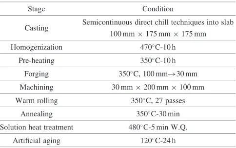
Table 2 Experimental procedure on Alloy M.
Stage Condition
Casting Semicontinuous direct chill techniques into slab 100 mm175 mm175 mm
Homogenization 470C-10 h
Pre-heating 350C-10 h
Forging 350C, 100 mm!30 mm
Machining 30 mm200 mm100 mm
Warm rolling 350C, 27 passes
Annealing 350C-30 min
Solution heat treatment 480C-5 min W.Q.
Artificial aging 120C-24 h
30 mm high. The forged sample was machined with dimensions of 30 mm high, 200 mm wide and 100 mm long.
This block was rolled at 350C with re-heating at 350C for
1800 s after every two passes up to 4 mm thick followed by every pass up to 1 mm thick. 27 rolling passes (one pass reduction; 2 mm per pass up to 10 mm thick, 1 mm per pass up to 9 mm thick and 0.5 mm per pass up to 1 mm thick) were carried out in total and the sheets were finally prepared with dimensions of 1 mm thick and 200 mm wide.
The surface temperatures of the rolls were controlled at
approximately 100C by cylindrical heaters. The roll was
160 mm in diameter and rotated 120 revolutions a minute. Commercial machine oil was used in the warm rolling process.
Regarding the alloy S, hot rolled plates used in this study were produced commercially by making use of a large slab by semi-continuous direct chill technique. The plates were
heated as an intermediate annealing at 480C for 2 h followed
by furnace cooling, then rolled to 1 mm thick at an ambient temperature.
Solution heat treatment was carried out at 480C for 300 s
followed by quenching into water immediately (T4 con-dition). After the quenching, artificial aging was carried out
at 120C for 24 h (T6 condition).
Microstructure was observed using an optical microscope and a transmission electron microscope (TEM). Misorienta-tion angles between grains were measured using electron backscattered diffraction (EBSD) equipment with a scanning electron microscope (SEM). X-ray diffraction method was used to describe incomplete pole figures, and orientation distribution functions (ODFs) were calculated from three incomplete pole figures of {111}, {110} and {100} by the
harmonic method.8)The ODFs were displayed using Bunge’s
system.8) The mechanical properties of the samples in T6
condition were investigated. Tensile test specimens were got
from the orientations of 0, 45 and 90 to the rolling
direction. The specimens for limiting draw ratio (LDR)
measurement were annealed at 360C for 2 h followed by
furnace cooling9) (O temper) to ensure deep drawing
property. LDR measurement was carried out with a punch of 33 mm in diameter in hold-down force of 3,900 N. The test method of resistance to stress corrosion cracking (SCC) in T6 condition was based on Japanese industrial standard, JIS H8711. The specimens for this test were got from the
orientation of 90to the rolling direction, and were immersed
in a solution containing 3.5 mass% sodium chloride for 10
minutes followed by drying at 25C for 50 minutes with
addition of stress controlled at 85% of yield strength. The above cycle was repeated until the specimens were failed. The resistance to SCC was estimated by a time to failure of the specimens. Exfoliation corrosion susceptibility was examined based on ASTM G34, EXCO test. Specimens in T6 condition were immersed for 9 h in a solution containing 4 M sodium chloride, 0.5 M potassium nitrate, and 0.1 M
nitric acid at 25C. The susceptibility to exfoliation was
determined by visual examination according to the standard photographs in the designation. Specimens of fatigue test were got from parallel to the rolling direction and machined with dimensions shown in Fig. 1. In this work, the axial loading fatigue test was conducted at a room temperature
with the stress ratio of 0.1 and the cyclic of 30 Hz.
3. Results
3.1 Microstructure in T4 condition
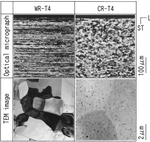
Figure 2 shows optical micrographs in L-ST section at the center and 30 mm position from the edge of the warm rolled sheet in T4 condition. Fibrous structure is maintained and no recrystallized grain is observed. Figure 3 compares micro-structures between the warm rolled and cold rolled sheets in T4 condition. In optical micrographs, it is found the cold
rolled sheet (CR) consists of equiaxed grains about 20mmin
Fig. 1 Shape and dimensions of fatigue specimen.
Fig. 2 Optical micrographs of warm rolled sheet in T4 condition.
[image:2.595.324.526.241.324.2] [image:2.595.307.547.368.498.2] [image:2.595.306.546.531.758.2]diameter, whereas the warm rolled sheet (WR) maintains fibrous structure as mentioned above. In TEM, it is revealed the warm rolled sheet consists of fine grains whose average
diameter is approximately 3mm. According to the previous
work,4)fine particles are judged as Al
3Zr in alloy M (warm
rolled sheet) and Al18Cr2Mg3 in alloy S (cold rolled sheet).
3.2 Distribution of misorientation angle in T4 condition
Figure 4 shows misorientation angle histograms taken from SEM-EBSD measurements. The measured area in this
work was 100mm200mm. The warm rolled sheets have a
high proportion of low angle boundary less than 15, whereas
the cold rolled sheet has a high proportion of high angle boundary. According to this measurement, it is clear the warm rolled sheet consists of subgrain structure.
3.3 Tensile properties and LDR measurements
Table 3 summarizes tensile test results in T6 condition. The tensile strength of the warm rolled sheet is about 10%
higher in orientations of 0 and 90to rolling direction than
that of the cold rolled sheet, and the tensile strength in 45
[image:3.595.63.280.70.336.2]direction is almost same level in the both sheets. The warm rolled sheet has an anisotropy on ductility, whereas the cold rolled sheet tends to be isotropic on it as well as tensile and yield strengths.
Figure 5 shows the plastic strain ratio of width to thickness (Lankford value: r-value) measured at 10% elongation. It is remarkable point that the warm rolled sheet has a quite high
value over 3.5 in the orientation of 45 to the rolling
direction. The warm rolled sheet also shows anisotropy on r-value. The average r-value of the warm rolled sheet is 2.2, meanwhile that of the cold rolled sheet is 0.6.
The results of LDR measurements are shown in Table 4. The warm rolled sheet tends to have a higher value than the cold rolled sheet, and it is found that the LDR values have correlation with the average r-values shown in Fig. 5.
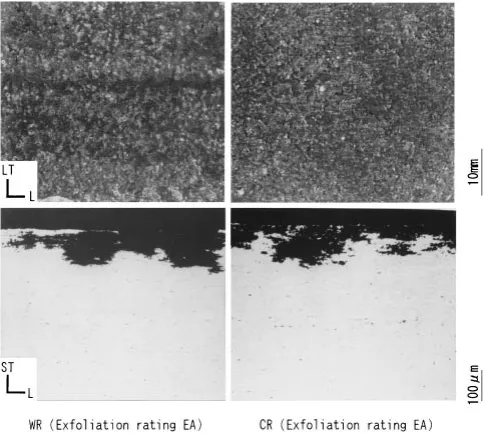
3.4 Corrosion resistance
Figure 6 shows the life of SCC in T6 condition. The warm rolled sheets have better resistance to SCC than the cold rolled sheets. Figure 7 shows the appearances and photo-0
10 20 30
0 5 10 15 20 25 30 35 40 45 50 55 60 Misorientation angle (Degrees)
Relativ
e n
umber (%)
0 10 20 30
0 5 10 15 20 25 30 35 40 45 50 55 60 Misorientation angle (Degrees)
Relativ
e n
umber (%)
(a) warm rolled sheet
(b) cold rolled sheet
Fig. 4 Misorientation angle histograms of (a) warm rolled sheet and (b) cold rolled sheet in T4 condition.
Table 3 Mechanical properties of warm rolled sheet and cold rolled sheet in T6 condition.
Condition Angle to RD Tensile strength Yield strength Elongation
(MPa) (MPa) (%)
Alloy M 0 592 496 13
WR-T6 45 522 461 19
90 601 455 13
Alloy S 0 522 461 16
CR-T6 45 521 457 17
90 526 468 16
[image:3.595.322.531.71.222.2]Fig. 5 Plastic strain ratio of width to thickness in T6 condition. WR: warm rolled sheet, CR: cold rolled sheet,rr: average r-value.
Table 4 Limiting drawing ratio of warm rolled sheet (WR) and cold rolled sheet (CR).
WR CR
LDR 2.06 2.00
0 200 400 600 800
WR-T6 CR-T6
Time (h)
[image:3.595.302.550.558.757.2] [image:3.595.46.291.679.786.2]micrographs of the L-ST section after EXCO test. The both sheets have the same classification and are estimated of EA.
3.5 Fatigue strength
Figure 8 gives S-N curves of the samples in T6 condition. The fatigue strength of the warm rolled sheets is about 10% higher than that of the cold rolled sheets. It is well known that fatigue strength increases with increasing tensile strength.10) Furthermore, the effect of the fibrous structure in the warm rolled sheets on the fatigue strength should be examined in future.
4. Discussions
One of remarkable properties on the warm rolled sheets is high r-value shown in Fig. 5. According to the previous work11)based on Taylor theory,12)it was predicted that the
r-value of 45orientation would be increased by af011gh211i
Brass component. Figure 9 shows the ODFs at the surface layer and center layer of the samples used in this work. The
f011gh211iBrass component is formed strongly through the
thickness of the warm rolled sheet. Regarding to the center
layer of the warm rolled sheet, other’2sections are shown in
Fig. 10. Another orientation near af123gh634iS component
is perceived but its orientation density is lower than the Brass
component. It is well known that-fiber orientations involve
Brass, S and C components. However, a f112gh111i C
component was not perceived through the thickness of the warm rolled sheet. According to the above texture analysis,
the highr-value of the orientation of 45in the warm rolled
sheet will be derived from the high orientation density of the Brass component. The present results are in agreement with
the previous work11)mentioned above. Regarding to the cold
rolled sheets, as shown in Fig. 9, ND- and RD-rotated Cube
components as well as a f011gh100i Goss component are
perceived. Their orientation densities are much lower than the Brass component in the warm rolled sheets. Besides of these quite well defined recrystallization texture components, the ODFs comprise the random component. Accordingly, the very weak recrystallization textures with the random com-ponent will lead to isotropic tensile properties of the cold
rolled sheets. The cold rolled sheets consisted of -fiber
components in as rolled condition, but the orientation density of the Brass component before solution heat treatment was
much lower than that of the warm rolled sheets.5)It would be
thought that the strong Brass component in the warm rolled sheets is due to the formation of fine subgrain structure that is quite stable thermally.
In the present work, specimens in O-temper were used for LDR measurements. This O-temper treatment was carried
out at 360C after the solution heat treatment at 480C, so
that it was confirmed the textures of specimens didn’t change by the O-temper treatment. Based on this confirmation, it
would be found that the average r-values have correlation
with the LDR values. It would be another subject that precipitation condition may affect drawing properties, but this consideration is beyond the scope of the present work. Fig. 7 Appearance and photomicrographs showing cross sections of warm
rolled sheet (WR) and cold rolled sheet (CR) exposed to the standard EXCO solution for 9 h.
0 50 100 150 200
4 6 8
Number of cycles to failure
Stress am
p
litude (MP
a)
10 10 10 10 10
Warm rolled sheet Cold rolled sheet
5 7
Fig. 8 Stress-number of cycle curves for the specimens in T6 condition.
ϕ1
: Brass{011}<211> : Goss{011}<100> : Cube{001}<100>
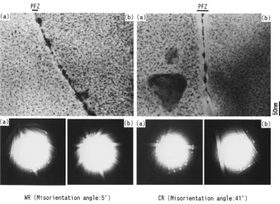
[image:4.595.306.548.72.317.2] [image:4.595.48.291.73.290.2] [image:4.595.72.266.350.479.2]In the previous work,6) influence of alloy elements in AA7075 was investigated. It was found in the work that addition of zirconium brought about reduction of SCC life in T6 condition. The reason why the warm rolled sheets containing zirconium have good resistance to SCC may be derived from its microstructure. In the previous study on
AA6061 alloy extrusions,13)it was suggested the formation of
a precipitate free zone (PFZ) is restrained at a low angle boundary, which leads to high resistance to intergranular corrosion. Figure 11 shows TEM images of the samples in T6 condition and Kikuchi patterns derived from two grains facing each other across a grain boundary. From Kikuchi pattern analysis, it was confirmed that a low angle boundary is observed in the warm rolled sheet and a high angle boundary is observed in the cold rolled sheet. It is clearly found that a PFZ is restrained at the low angle boundary, whereas a PFZ is formed distinctly at the high angle boundary. Other grain boundary areas of the both sheets showed the same characteristic on the PFZ formation. In the
case of narrow PFZ formation, the difference of electro-chemical property between the grain boundary area and the grain interior tends to reduce, which would prevent a partial anodic reaction and lead to the improvement of resistance to SCC.14,15)
5. Conclusions
The mechanical properties on the warm rolled sheets of AA7475 based aluminum alloy containing zirconium with fine subgrain structure were investigated comparing with conventional AA7475 aluminum alloy sheets produced by cold rolling. The following points can be made:
(1) The warm rolled sheets show the high r-value of 3.5 in the
orientation of 45to rolling direction due to well developed
-fiber components, especially with the strong f011gh211i
Brass component after solution heat treatment.
(2) The average r-value of the warm rolled sheets is higher than that of the cold rolled sheets, so that the warm rolled
ϕ2 ϕ2 ϕ2
[image:5.595.116.482.78.200.2]ϕ
Fig. 10 ODFs of the warm rolled sheet at the center layer in T4 condition.
[image:5.595.99.496.235.524.2]sheets have better deep drawing properties in O-temper. (3) PFZ is hardly formed along the low angle boundaries of the warm rolled sheets in T6 condition, which would lead to the improvement of resistance to SCC because of the uniformity of electrochemical property between the grain boundary area and the grain interior.
(4) The fatigue strength of the warm rolled sheets in the
orientation of 0to rolling direction is about 10% higher than
that of the cold rolled sheets.
Acknowledgements
This work was supported in part by a research fund of the Super Aluminum Project provided by the Japan Research and Development Center for Metals (JRCM) in the New Energy and Industrial Technology Development Organization (NE-DO). The authors thank JRCM and NEDO for the permission of publication of this report.
The authors also acknowledge Professor Z. Horita, Kyushu University in Japan, for the measurements of the grain boundary misorientations by Kikuchi lines of TEM images.
REFERENCES
1) E. O. Hall: Proc. Phys. Soc.64(1951) 747. 2) N. J. Petch: Iron Steel Inst.25(1953) 197.
3) The Society of Japan Aerospace Companies: Investigation for the promotion of aero parts and materials industries No. 807, (1994). 4) T. Minoda, H. Tanaka, K. Shibue and H. Yoshida: J. Japan Inst. Light
Metals51(2001) 651.
5) H. Tanaka, T. Minoda, H. Esaki, K. Shibue and H. Yoshida: J. Japan Inst. Light Metals52(2002) 29.
6) The Society of Japan Aerospace Companies: Investigation for the promotion of aero parts and materials industries No. 904, (1995). 7) H. Tanaka, T. Minoda, H. Esaki, K. Shibue and H. Yoshida:
Proceedings of 8th International Conference ICAA8, Cambridge, UK, (2002), 499.
8) H. J. Bunge: Texture analysis in materials science, (Butterworths, 1982).
9) S. Hirano and H. Yoshida: Sumitomo Light Metal Technical Reports38
(1997) 95.
10) K. Takeuchi: J. Light Metal Welding and Construction4(1966) 184. 11) H. Inoue and N. Inakazu: J. Japan Inst. Light Metals44(1994) 97. 12) G. I. Taylor: J. Inst. Metals62(1938) 307.
13) T. Minoda and H. Yoshida: Metall. Mater. Trans. A33A(2002) 2891. 14) E. N. Pough and W. R. D. Jones: Metallurgia63(1961) 3.