Memory Cell Simulation on the Nanometer Scale
Heinz-Olaf Müller and Hiroshi Mizuta, Member, IEEE
Abstract—We describe a toolset of simulation programs and
its use for the simulation of a memory cell based on Coulomb blockade. We present simulation results both for the main param-eters of the memory cell and the influence of parasitic effects. We point out that both setting up specific programs and providing data exchange between them is necessary in order to describe the memory cell to a realistic extent.
Index Terms—FET memory integrated circuits, intelligent
de-sign assistants, memory architecture.
I. INTRODUCTION
T
HE GAIN-CELL concept as devised in flash memory paved the way toward the use of less charge per bit ( , elementary charge) in electronic memory. In future this might lead to Coulomb blockade (CB) based memory cells using even less charge ( ) and direct tunneling instead of Fowler–Nordheim tunneling.In this paper we report on the simulation of a CB memory cell. This is a lateral single electron memory cell (LSEM cell) as shown in Figs. 1 and 2. It was proposed [2] recently and its operation was demonstrated [3]. The CB device of the demon-strated cell was a silicon multiple tunnel junction. However, a granular metallic film can be used instead, thus even simplifying the cell layout owing to the unnecessary trimming gate. The de-tails of the working principle are outlined in Section II. Making use of a variety of simulation tools (Section III) we assess the potential of the LSEM concept and evaluate its value in terms of reliability. The resultant data are shown in Section IV.
We concentrate on new, unpublished, material, which demon-strates the interconnection of our simulation tools. We kindly refer the reader to the references for specific aspects of the sim-ulation.
II. LSEM OPERATION
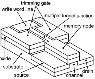
The LSEM cell as shown in Figs. 1 and 2 belongs to the gain-cell type of memories. Fig. 2 provides an oblique view of an implementation in silicon on insulator (SOI). The read word line is left out for clarity. Write/erase uses the displayed write word line. Through a silicon multiple tunnel junction [4] charge is transferred to or from the memory node when an appropriate write word line voltage is applied. A trimming gate is used to control the working point of the multiple tunnel junction, the Coulomb blockade of which confines the charge on the memory
Manuscript received April 26, 2000. This work was performed within the ESPRIT MEL-ARI project FASEM (Fabrication and Architecture of Single-Electron Memories). The review of this paper was arranged by Editor R. W. Dutton.
The authors are with the Cavendish Laboratory, Hitachi Cambridge Labora-tory, Cambridge CB3 0HE, U.K. (e-mail: [email protected]).
[image:1.612.329.525.143.259.2]Publisher Item Identifier S 0018-9383(00)07773-X.
Fig. 1. Schematics of the suggested LSEM cell: (a) Layout of the cell, the CB device connects write word line and memory node for the write/erase process. The read word line implements a built-in row select. The memory cell is read out via the transistor beneath read word line gates and memory node (gain-cell operation). Crucial dimensions are the memory node width (0:1 m) and the source drain separation (0:3 m). (b) LSEM cell array illustrating the incorporated row select by means of the read word line.
Fig. 2. Simplified layout of the LSEM cell without read word line as fabricated in SOI with extremely thin oxide (20 nm).
node. The read out process uses a MOSFET that is implanted into the bulk silicon of the SOI wafer underneath the memory node and the read word line gates. This enables gain-cell oper-ation, as the charge state of the memory node thus controls the current through the read out transistor. The read word line gates allow for an built-in row select.
III. SIMULATIONTOOLS
A comprehensive simulation package for the LSEM cell con-sists of at least three parts: 1) capacitance simulation, 2) de-vice level simulation, and 3) circuit level simulation. In order to model the fabrication of CB devices the simulation package has to be supplemented by corresponding process simulation soft-ware. Full-feature – characteristics of CB devices using an
[image:1.612.350.508.369.501.2]orthodox lumped-element model also require a tunneling resis-tance model.
A. CB Device Simulation
Capacitance simulation is central to the understanding of CB devices since their characteristic energy scale, the charging en-ergy , is directly correlated via , where is the capacitance of the electrode under consideration [5]. For metallic systems, where the problem is merely a computational one, the FastCap program1 enjoys the status of a quasi standard,
but new theoretical/numerical approaches [6] and commercial programs are emerging. For semiconducting systems, namely quantum dots, the computation is much more involved and a challenge in itself [7].
Our capacitance simulation is based upon an analytical formula for homogeneously charged rectangular electrodes. [8] Larger, irregular, inhomogeneously charged, but still planar electrodes can also be assembled. Accuracy problems arising from the use of very small cells can be addressed by a higher-order expansion of the original formula, [9] but similar problems persist for cells with large aspect ratio. The common plane of the electrodes is considered to be sandwiched between two semi-infinite dielectrics. Despite the limitation of the approximation as well as the computation time for large systems, the method yields realistic results for both metallic [10] and semiconducting [11] systems.
The output of the capacitance computation is the complete capacitance matrix for the structure including the self-capaci-tance of each electrode, which allows for an estimate of the cor-responding stray capacitance. The capacitance setup describes the electrostatic interaction of the macroscopic system.
Together with a model of the resistance, it is possible to com-pute a current through a CB device in an orthodox lumped-ele-ment scheme. The resistance is a tunneling resistance and thus depends strongly on the characteristics of the tunneling barrier. The values obtained were found to vary considerably with slight changes of the barrier parameters and are generally less reliable than the capacitance computation. Nevertheless, a number of re-sistance formulae for different systems exist [13]. For metallic systems we have used a recent approximation [14] to simulate the current through a granular film [15].
B. Device Level Simulation
An important point in the LSEM cell design is the coupling from the CB part of the cell to the more standard parts. For our specific example, the coupling is achieved by the memory node, which is charged and discharged via a lateral CB device and whose charge state is sensed by a MOSFET underneath. Device level simulation is employed to study this coupling as well as corresponding parasitic effects. Furthermore, estimates of the selectivity of the memory cell rely on device level simulation.
In the case of the LSEM cell, commercial device level sim-ulation (Atlas v4.0.3.R, © Silvaco International, Inc.) is suf-ficient due to the macroscopic, however still sub- m size of the memory node. Depending on the operation principle of the memory cell this might not hold for a different memory concept.
1ftp://rle-vlsi.mit.edu/pub/fastcap/fastcap-2.0-18Sep92.tar.Z
For CB memory structures, which probably will have to rely on gain-cell operation and—therefore—incorporated MOSFETs, the advantage of memory node coupling of the LSEM cell is evident. Therefore, the approach presented here is rather gen-eral.
C. Circuit Level Simulation
Conventional circuit level simulation is usually SPICE based. Therefore, it became very attractive to connect the simulation of CB devices [16]–[19] with a SPICE simulator as achieved re-cently [20], [21]. Whereas for simple CB devices, like the single electron transistor, the direct solution of the orthodox master equation [22] provides an efficient means for an accurate com-putation of the tunneling current as well as conductance, more complex setups have to rely on Monte Carlo techniques [17] which have an intrinsic difficulty in providing smooth differen-tial conductance data and thus complicate co-operation with the SPICE environment. However, these problems were addressed and—to some extent—solved recently [20], [21].
IV. RESULTS
For different reasons we select only a few results for discus-sion in this section. First, a fair amount of work on specific parts of the memory cell simulation has been published in recent years. Second, the emphasis of this paper is rather on the inter-connection of different simulation tools than specific aspects of the simulation.
Therefore, our main example uses CB simulation to extract the blockade voltage from the geometry of the CB device. This parameter is then used in a device level simulation to tune the outer voltage regime (read/write process) and dynamic behavior of the memory cell. In our case, the contents of the memory cell is read via the transistor current. This value enters, for instance, the sense amplifier simulation, where it determines the value of the input resistance or the corresponding voltage
(Fig. 6).
A. CB Device Simulation
The hysteresis of the employed CB device is a cardinal point of the LSEM operation. Therefore, simulation of the CB device has a significance in its own right.
The LSEM cell as presented in Section II contains a silicon multiple tunnel junction as CB device. First simulation results for this system were presented recently [23], [24]. For the layout using a granular metallic film—as mentioned above—exist cor-responding simulations [15].
In the latter case, which is still a topic of lively scientific dis-cussion, we find that multiple tunnel junctions provide some im-munity to background charge disorder. Only specific, partly co-herent, and therefore highly unlikely patterns of these charges result in a complete breakdown of CB. On the other hand, there are also patterns of background charges which cause actually an increase of ,i.e., if they alternate along the current direction.
Of course, a CB breakdown would prohibit the memory cell operation, but also too wide a distribution would hinder an application since , being the write word line voltage, influences the write time exponentially [26]. The design goal is therefore a sharp distribution. The average of this dis-tribution can be used to estimate the operation temperature via . Our results for 5 nm dot yield an operation tem-perature of about 30K and require size control of nm [12].
The consideration of the tunneling resistances and the related computation of full – characteristics is easier to achieve for metallic than for semiconducting systems since the free electron model can be used [13]. This was demonstrated recently [15] using a model closely linked to experimental data [14].
In the case of semiconducting CB devices the problem can be circumvented by the use of a priori resistance values which can be stepped through a reasonable range [26]. This allows for the evaluation of the write/erase process as outlined in Section II in terms of speed and stability. A complete set of timing diagrams for the different operations exists.
B. Device Level Simulation
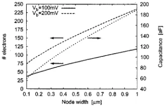
Mainly, device level simulation is useful for the optimization of the memory cell layout. In some cases a simple capacitance calculation already provides interesting data. In Fig. 3, we dis-play the number of electrons used for coding one bit of infor-mation as a function of the memory node geometry. This pa-rameter is important for the comparison with conventional dy-namic random access memory (DRAM) ) and flash memory ( ) since it is strongly related to the power consumption. The simulation uses the blockade voltage of the CB device as an input parameter, which in turn can be ob-tained from a CB device simulation similar to those in [12].
A standard example of device level simulation is the study of the read out process as a function of the read out transistor geometry as shown in Fig. 1 [2]. Some design parameters, like the gate oxide which is the oxide layer of an SOI wafer, are constrained by the technology. For others, there exist tradeoffs. One example is the memory node width. A wide memory node at the expense of the read word line gate width would cause slow charging and discharging. On the other hand, too small a memory node cannot shut off the transistor channel beneath and thus complicates the read out process. These questions are discussed in [2] extensively.
[image:3.612.346.510.62.168.2]Another instructive piece of device level simulation is pre-sented in Fig. 4, the (parasitic) coupling between read word line and memory node. The proximity of the “enable” gates of the read word line to the memory node causes a capacitive feedback. The task consists of two parts, the investigation of the charging process of the memory node and of the change of the obtained charge state as function of read word line voltage and write word line voltage .
Fig. 3. Capacitance of the memory node of the LSEM cell and number of electrons on the node as function of the blockade voltageV for different memory node widths.
Fig. 4. Feedback of the read word line voltage onto the memory node charge: (a) A 10-ns voltage pulse of variable voltage V is applied to the write word line. In the following 10 ns the charge relaxation of the memory node is observed. (b) Corresponding memory node charge ranging from 0 (white) to 180e (black). The blockade voltage is about 0.2 V and the memory node holds a maximum of about 80 charges. (c) After charging the memory node as shown in (a) and (b), both read word line and write word line are biased and the resultant memory node charge is plotted. Increasing read word line voltage depletes the charge state of the memory node. An increasing write word line voltage counteracts this process. The charge varies between0290 e (bottom right corner) and 190e (top left corner). (d) Same as (c) for the equilibrium memory node. The same charge scale applies.
[image:3.612.326.531.225.372.2]Charging of the memory node is shown in Fig. 4(a) and (b). For memory operation this corresponds to writing “1” into the memory cell. This is done by applying a voltage pulse of 10 ns to the write word line while keeping the read word line grounded [Fig. 4(a)]. Depending on the voltage of this pulse, , three different scenarios are observed [Fig. 4(b)]. If Coulomb blockade prevents charging of the node (in the displayed example: V). For , where is the number of charges the memory node can hold if the leads are grounded ( ) and is the node capacitance ( aF), charging of the memory node is propor-tional to . For even higher bias of the write word
line, the memory node becomes
over-charged during the voltage pulse, but its charge relaxes to as soon as the bias is switched off.
Fig. 5. Current through the read out transistor of the LSEM cell as function of the misalignment of memory node and read word line gate. (a) The current as function of the memory node voltageV . The read word line is enabled (V =0.2 V) and the memory node width and implant separation are 0.1
m and 0.9 m, respectively. The misalignment increases from 0 (bottom) to 1 m (top). (b) The parasitic current for different width of the memory node and
different implant separation (0.5m misalignment).
memory node charge. The difference is the wide CB region of the uncharged node in Fig. 4(d), which prevents from pushing charges back into the write word line and from overcharging the memory node, similar to Fig. 4(a). If Fig. 4(c) displays state “1” of the memory cell and Fig. 4(d) “0” than we can learn from Fig. 4(c) that is the condition for preserving “1.” is the similar condition for the “0” state. Therefore the read-out scheme [2] has to rely on suf-ficiently small values of [2].
In the fabrication of real LSEM, misalignment of the memory node and the read word line gates might occur. The estimate of the parasitic current due to this effect is another example of de-vice level simulation, this time using the 3-D features of the sim-ulation program. In Fig. 5(a) the transistor current is shown for an enabled read word line ( V) and different values of the misalignment ranging from 0–1 m in steps of 50 nm. Misalignment is the length difference between read word line gate and memory node. In principle there is also the case of negative , however the small width of the memory node compared to the read word line gates prohibits a reasonable tran-sistor current. Despite the case of very small misalignment, the effect is an additional parasitic current which cannot be con-trolled by the memory node. In Fig. 5(b) we plot this current in dependence of the memory node width and the implant separa-tion for 0.5 m misalignment. The parasitic current can be
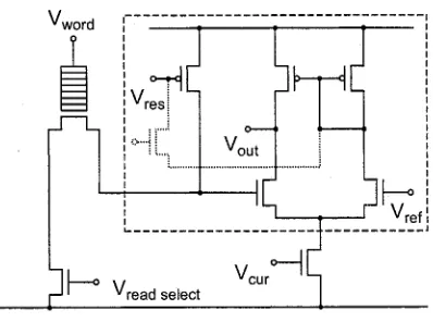
effec-Fig. 6. Possible refresh organization for the LSEM memory cell. The top left corner displays the (simplified) memory cell. The dashed box contains the sense amplifier. The dotted refresh transistor communicates the reverse sense amplifier output to its input current converter, thus pulling up or down the data line.
tively suppressed by a wider memory node, but at the expense of the cell performance. There is also an effect of the implant separation, especially for a very narrow memory node. This is probably the better way to suppress the parasitic current.
C. Circuit Level Simulation
The LSEM circuitry simulation is a conventional SPICE sim-ulation as far as the sense amplifier and other circuit elements are concerned. This part of the task is not presented in this paper. There are, however, cases where the combined simulation of the CB device and the read out transistor are important, and com-prehensive simulation software [20], [21] becomes necessary.
One example is the simulation of the hysteresis curve of a single LSEM cell as presented in [23], [24]. These hysteresis curves shows additional features,i.e., steps, [3] which can be un-derstood by use of comprehensive simulation and an appropriate model of the multiple tunnel junction. Not only the appearance of the steps is explained—replica of the integrated Coulomb os-cillations—but also some of their detailed features. More nega-tive voltage of the trimming gate (see Fig. 1) causes fewer, but larger steps. For fixed trimming gate voltage the step size in-creases with the write word line voltage.
Closer to current technology is the example of the memory cell refresh, which is one of the basic principles of DRAM op-eration. The operation is based on the fact that refresh is possible via the data line (refer to Fig. 1). For gain-cell based memory, like flash memory, the electrical separation between memory node and data line obstructs refresh which is usually no problem, since flash memory is a nonvolatile memory. The situation is dif-ferent for the LSEM cell which generally is assumed to be rel-atively volatile [2]. Capacitive coupling between memory node and data line might provide a possible route to refresh in this case. This coupling works similarly to the parasitic read word line coupling discussed above, but uses the implanted data line instead of the read word line.
[image:4.612.328.527.69.217.2]capac-itance of the cell’s read out transistor this might be sufficient to reestablish the original charge state of the memory node. A quantitative analysis of the operation has still to be performed.
V. CONCLUSION
The advent of Coulomb blockade (CB) based electronics re-quires new simulation tools and their cooperation with existing software. Using the example of a CB memory cell we illustrate this situation. In our discussion, we provide examples of cell design (memory node width), parameter extraction (number of electrons per bit), and error analysis (memory node misalign-ment). We show different cases of data exchange between pro-grams from a single extracted parameter (blockade voltage) up to complex program interaction.
ACKNOWLEDGMENT
The authors thank M. Wagner for help with the numerics and their discussion and D. A. Williams for helpful discussions.
REFERENCES
[1] See, [email protected].
[2] K. Katayama et al., “Design and analysis of high--speed random ac-cess memory with Coulomb blockade charge confinement,” IEEE Trans.
Electron Devices, vol. 46, Nov. 1999.
[3] Z. A. K. Durrani, A. C. Irvine, H. Ahmed, and K. Nakazato, “A memory cell with single-electron and metal-oxide-semiconductor transistor inte-gration,” Appl. Phys. Lett., vol. 74, p. 1293, 1999.
[4] K. Nakazato and H. Ahmed, “The multiple tunnel junction and its appli-cation to single-electron memories,” Adv. Mater., vol. 5, p. 668, 1993. [5] H. Grabert and M. H. Devoret, Single Charge Tunneling: Coulomb
Blockade Phenomena in Nanostructures, ser. NATO ASI Ser. B:
Phys.. New York: Plenum, 1992, vol. 294.
[6] H. H. Pham and A. Nathan, “A new approach for rapid evaluation of the potential field in three dimensions,” Proc. R. Soc. Lond. A, vol. 455, p. 637, 1999.
[7] M. Stopa, “Quantum dot self-consistent electronic structure and the Coulomb blockade,” Phys. Rev. B, vol. 54, p. 13 767, 1996.
[8] H. Pothier, “Blocage de Coulomb et transfert d’electrons un par un,” Ph.D. dissertation, Univ. Paris, Paris, France, 1991.
[9] M. Wagner and K. Nakazato, “Calculation of capacitance of planar elec-trodes,”.
[10] E. M. Ford and H. Ahmed, “Control of Coulomb blockade character-istics with dot size and density in planar metallic multiple junctions,”
Appl. Phys. Lett., vol. 75, p. 421, 1999.
[11] N. J. Stone and H. Ahmed, “Silicon single electron memory cell,” Appl.
Phys. Lett., vol. 73, p. 2134, 1998.
[12] H.-O. Müller, K. Katayama, and H. Mizuta, “Effects of disorder on the blockade voltage of two-dimensional quantum dot arrays,” J. Appl.
Phys., vol. 84, p. 5603, 1998.
[13] J. G. Simmons, “Generalized formula for the electric tunnel effect be-tween similar electrodes separated by a thin insulating film,” J. Appl.
Phys., vol. 34, p. 1793, 1963.
[14] A. S. Cordan et al., “Electron transport in metallic dot arrays: effect of a broad dispersion in the tunnel junction dimensions,” J. Appl. Phys., vol. 84, p. 3756, 1998.
[15] H.-O. Müller et al., “Origin of yield problems of single electron devices based on evaporated granular films,” Appl. Phys. Lett., vol. 75, p. 1634, 1999.
[16] L. R. C. Fonseca, A. N. Korotkov, K. K. Likharev, and A. A. Odintsov, “A numerical study of the dynamics and statistics of single electron sys-tems,” J. Appl. Phys., vol. 78, p. 3238, 1995.
[17] K. P. Hirvi, M. A. Paalanen, and J. P. Pekola, “Numerical investiga-tion of one-dimensional tunnel juncinvestiga-tion arrays at temperatures above the coulomb blockade regime,” J. Appl. Phys., vol. 80, p. 256, 1996. [18] R. H. Chen, A. N. Korotkov, and K. K. Likharev, “Single-electron
tran-sistor logic,” Appl. Phys. Lett., vol. 68, p. 1954, 1996.
[19] C. Wasshuber and H. Kosina, “A single-electron device and circuit sim-ulator,” Superlattices Microstruct., vol. 21, p. 37, 1997.
[20] S. Amakawa et al., “Single-electron circuit simulation,” IEICE Trans.
Electron., vol. E81–C, p. 21, 1998.
[21] M. Kirihara, K. Nakazato, and M. Wagner, “Hybrid circuit simulator including a model for single electron tunneling devices,” Jpn. J. Appl.
Phys., vol. 38/1, p. 2028, 1999.
[22] D. V. Averin and K. K. Likharev, Mesoscopic Phenomena in Solids,
Modern Problems in Condensed Matter Sciences (30), B. L. Altshuler,
P. A. Lee, and R. A. Webb, Eds. Amsterdam, The Netherlands: Else-vier, 1991, pp. 173–271.
[23] H.-O. Müller et al., “Simulation of silicon multiple tunnel junctions,”
Phys. B, vol. 272, p. 85, 1999.
[24] H.-O. Müller et al., “Simulating silicon multiple tunnel junctions from pinch-off to ohmic conductance,” Mater. Sci. Eng. B, vol. 74, p. 36, 2000. [25] J. A. Melsen, U. Hanke, H.-O. Müller, and K. A. Chao, “Coulomb blockade threshold in inhomogeneous one-dimensional arrays of tunnel junctions,” Phys. Rev. B, vol. 55, p. 10 638, 1997.
[26] H. Mizuta et al., “High-speed single-electron memory: Cell design and architecture,” in Proc. 2nd International Workshop on Physics and
Mod-eling of Devices Based on Low-Dimensional Structures. Los Alamitos,
CA, 1998, pp. 67–72.
Heinz-Olaf Müller received the Dipl. and Ph.D.
de-grees in physics from the Friedrich Schiller Univer-sity, Jena, Germany, in 1990 and 1994, respectively.
He was awarded a Post-Doctoral Fellowship with the Norwegian University of Science and Technology (NTNU), Trondheim, Norway, by the German Academic Exchange Council from 1995 to 1996. After a period with Lund University, Lund, Sweden, he joined Hitachi Cambridge Laboratory, Cambridge, U.K., in 1997. He is currently involved in the design and simulation of single-electron memory cells within the EU-funded FASEM project (fabrication and archi-tecture if single-electron memory). He is also studying leakage mechanisms in poly-Si thin-film transistors.
Hiroshi Mizuta (M’89) was born in Kochi, Japan,
in 1961. He received the B.S. and M.S. degrees in physics and the Ph.D. degree in electrical engineering from Osaka University, Osaka, Japan, in 1983, 1985, and 1993, respectively.
He joined the Central Research Laboratory, Hitachi Ltd., Tokyo, Japan, in 1985 and has been engaged in research on numerical simulation of heterojunction devices as well as the study of resonant tunneling devices. From 1989 to 1991, he has worked on quantum transport simulation, and also since 1997 he has been working on single-electron devices and other quantum devices at the Hitachi Cambridge Laboratory, Hitachi Europe Ltd., Cambridge, U.K.