On the Identification of Agents
in the Design of Production Control Systems
Stefan Bussmann1, Nicholas R. Jennings2, and Michael Wooldridge3 1DaimlerChrysler AG, Research and Technology 3
Alt-Moabit 96A, 10559 Berlin, Germany. [email protected] 2Dept. of Electronics and Computer Science, University of Southampton
Southampton SO17 1BJ, United Kingdom. [email protected]
3Dept. of Computer Science, University of Liverpool Liverpool L69 7ZF, United Kingdom. [email protected]
Abstract. This paper describes a methodology that is being developed for designing and building agent-based systems for the domain of production control. In particular, this paper deals with the steps that are involved in identifying the agents and in specifying their responsibilities. The methodology aims to be useable by engineers who have a background in production control but who have no prior experience in agent technology. For this reason, the methodology needs to be very prescriptive with respect to the agent-related aspects of the design.
1 Introduction
Software agents are on the verge of becoming a key control technology for large-series production control systems. With ever shorter product life-cycles, decreasing product launch times, and increasing product variety, manufacturing processes must provide more product flexibility and higher volume scalability while maintaining high product quality and low manufacturing costs. Agent technology is well suited to addressing the control aspects of these new manufacturing requirements [2]. As autonomous decision-makers, agents are able to dynamically react to unforeseen events, exploit different capabilities of components, and adapt flexibly to changes in their environment. The ability of agents to adapt their behaviour at run-time reduces the need for the designer to foresee all possible scenarios and changes that the system will encounter: agents automatically adapt to changing products or varying volumes.
well as the on-going operation of the prototype, proved the industrial feasibility and underlined the competitive advantage of agent-based control. The technology is now ready to be exploited in industrial production.
The widespread use of agent -based control, however, will require software engineering methods and tools that support the development of industrial-strength control systems. Although we have some experience in the application of agent technology to cylinder head production, the application of agent technology to different production processes (such as engine assembly or car paint ing) will still require a major engineering effort. Such an engineering effort has to move agents out of the laboratory and into the planning teams designing manufacturing systems. Planning engineers, however, usually have no degree in agent technology or artificial intelligence. Therefore to make the technology accessible to them, agent-based control must provide a methodology that includes all the agent -related design rationales necessary to apply an agent-based approach to a manufacturing system. These design rationales tell a software engineer with no prior experience in agent development how to make agent -related design decisions. To this end, many software design methodologies have been developed, including object -oriented and even agent-oriented approaches (see [6,9] for an overview). But none of these methodologies is applicable to the design of agent -based production control systems; they either provide analysis models that are inappropriate for production control or else they lack comprehensive design rationales.
The aim of our research work is therefore to extend the state-of-the-art by proposing a methodology for the design of agent -based production control systems that can be successfully applied by an engineer with no prior experience in agent technology. To this end, the methodology should provide: (i) a model of the decision making necessary in production control in order to enable the designer to directly move from the domain to the agent-oriented design aspects; and (ii) a set of criteria for the design of the agent-related aspects which guide the designer with no prior agent-related experience. In this paper, we take the first significant step towards this goal by proposing a design method for identifying the agents of a production control system. The identification of agents is central to the methodology. It allows the designer to move from pure domain concepts (such as production processes), to agent-oriented concepts (such as agents and decision responsibilities). In addition, the identification of agents provides the basis for all other subsequent design steps, such as interaction design or agent programming.
1.1 What is a methodology?
A methodology is a recipe that enables an engineer to find a solution to a specified set of problems. It should be sufficiently precise to enable any engineer with a standard education to successfully apply the recipe to a suitable problem, while at the same time it should leave enough room for creativity. A methodology always consists of the following components [8].
• A definition of the problem space to which the methodology is applicable.
• A set of models that represent different aspects of the problem domain or the solution at different stages.
• A set of methods that transform instances of one model into another model.
• A set of procedural guidelines that define an order for the systematic application of the methodological steps.
The application of a methodology starts with a problem statement and ends with a solution to the problem. Methods and guidelines tell the designer how to go from the problem statement to the solution. An agent-oriented design methodology for production control is consequently a methodology that explains how to go from a specification of a production control problem to an agent-oriented design of a control system. However, for such a methodology to be widely used, the methodology must provide all necessary methods and guidelines such that an engineer with only minimal training and experience in agent development is able to successfully derive an agent-oriented design. This is achieved if the concepts of the methodology are intuitively related to the relevant concepts of the problem domain and if the methodology includes all the (agent-related) rationales necessary to derive the agent -oriented design. In terms of the above definition of a methodology, this translates into the following requirements.
Model appropriateness. The models of a methodology should be easily related to the relevant concepts of the problem domain. The initial model should be based on domain concepts and any new concepts should be put into relation to concepts already introduced. This applies in particular to the introduction of agent -oriented concepts.
Method prescriptiveness. The methods of the methodology should be prescriptive in the sense that they define each step the designer has to go through, and for each step clearly identify what the task of the designer is and – at least for any agent-oriented aspect – explain how the task should be performed. The methods must therefore clearly distinguish between domain and agent-oriented design reasoning.
As will be discussed in subsequent sections, the method for agent identification presented in this paper fulfils the above requirements and can therefore be seen as a first step towards an industrially relevant methodology for production control.
1.2 Production control
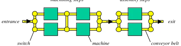
transportation system consisting of conveyor belts and switches (see Figure 1). During the operation of the production system, work pieces associated with specific jobs are fed into the production system, transported to the next station, processed by the station, moved to the next station, processed again and so on until the work pieces are finished and leave the system.
machining steps assembly steps
entrance exit
[image:4.612.154.459.208.287.2]switch machine conveyor belt
Fig. 1. Example production system.
For such a production system, the task of the control system is to assign jobs to stations (resource allocation) and to manage the material flow (transportation allocation). To date, the pre-dominant approaches to performing these tasks in practice have been to create a schedule beforehand, which is then simply executed at run-time by the local controllers of the production components. This approach works well if actions are executed as planned, but fails completely otherwise. In case of a disturbance, a controller is unable to execute its actions or has to postpone them. Since production operations are optimised in order to maximise productivity and minimise costs, resource capacities are fully utilised and buffer sizes are reduced to a minimum. As a consequence, any deviation from the schedule quickly affects neighbouring units resulting in a cascading effect of the disturbance. Since the schedule-driven control does not support re-scheduling, the impact of a disturbance on production cannot be constrained. As every real production system is regularly affected by disturbances, production operations soon deviate from the production schedule. It is even "proverbial among shop foremen that the schedules produced by the front office are out of date the moment they hit the floor" [19, p. 303].
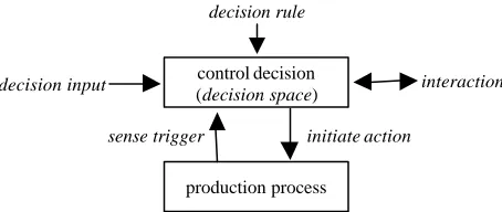
control decision (decision space)
sense trigger decision input
decision rule
production process
initiate action
[image:5.612.192.419.142.238.2]interaction
Fig. 2. Abstract model of control decisions.
This abstract model of a control decision is an obvious starting point of any design methodology for production control, since it describes the basic task of the controller and how it interfaces with the production process.
2
Related Work
With the shift from laboratory to industrial applications, it has become increasingly apparent that existing methodologies, such as purely object-oriented approaches, are insufficient to capture the key features of agent -based systems [1,14]. This experience has led to the development of distinctively agent -oriented design methodologies over the last few years. M ost agent-oriented methodologies have been extensions of existing methodologies, in particular knowledge -oriented and object -oriented approaches. Only recently have methodologies based on purely agent -oriented concepts been proposed.
The knowledge-oriented methodologies proposed for designing agent-based systems are extensions of the knowledge-engineering methodology CommonKADS [22], to which agent -oriented concepts are added. The CoMoMAS methodology [7] extends CommonKADS by adding a social analysis model, identifying social competencies of agents in terms of goals, intentions, and roles; and a co-operative analysis model, modeling co-operation and conflict resolution methods. MAS-CommonKADS [10] also extends MAS-CommonKADS by adding an agent, a co-ordination, and an organisation model. Because of the underlying knowledge-engineering approach, however, both methodologies view an agent system as a problem solving system decomposing the system task into subtasks. In this way they identify agents on the basis of task hierarchies and knowledge requirements. This model is inappropriate for the decision-centric view of production control.
models) on the basis of their activeness, that is, whether a component pro-actively performs or initiates an operation. Activeness, though, is also a property of conveyor belts or lifts, which actively move work pieces, but which do not decide whether or not to act. The activeness criterion can therefore identify as agents some entities that are not autonomous decision makers. This critique also applies to the methodology of Burmeister [1], which solely relies on object-oriented techniques to identify agents.
The limitations of methodologies that are based on concepts from other fields have led to the development of methodologies that are purely (or mostly) based on agent-oriented concepts. The dominant agent-agent-oriented concept used is that of a role. Kendall [13] defines a role as an abstraction of agent behaviour modelled in terms of responsibilities, possible collaborators, required expertise, and co-operation mechanisms used. The most important advantage of the concept of a role is that it can be freely assign and reassigned to agents, as long as the agent assigned to the role fulfils the role's requirements. Role-based methodologies, e.g., [5,14,15,17,18,23], use this abstraction to create a model of system behaviour, and then identify agents by mapping the roles to agent instances. The Gaia methodology [23], for instance, aggregates roles into agent types and instantiates as many agents as necessary in a given scenario.
Most role-based methodologies, however, require that the designer is able to directly identify the roles in an application. However, this is not possible in production control. A requirements specification of a production control system consists only of a description of the physical components of a production system and the production goals to be achieved. The specification of the physical components, in turn, only describes a sensor and actuator interface to each component. To identify roles in a specific production application, it is therefore necessary to derive an understanding of the required control process first. None of the methodologies, however, explain how the decision making should be modelled or combined to form roles. For production control, it is therefore necessary to extend these methodologies by a preceding analysis step that derives roles from the production control problem.
agents, and determining where there is decentralisation. Given our experience in this area, however, these principles are not sufficiently prescriptive to guide a designer in identifying agents.
To summarise, there is currently no methodology for the design of an agent-based production control system that satisfies the requirements stated in section 1.1. First of all, most methodologies provide analysis models unsuitable for representing the problem domain, i.e., to model the decision making necessary to control a production process. Second, nearly all methodologies provide criteria for agent identification that lead to an inappropriate set of agents for production control. It is therefore necessary to extend existing design methodologies by developing a design method that captures decision-making in its models and provides a comprehensive list of criteria for identifying agents. Such a design method could be used, for example, to identify (decision-based) roles of a production control application as required by the role-based methodologies.
3
Overview of the Design Method
The design method proposed in this paper identifies the agents necessary to control a given production process. The design method consists of two main steps: an analysis step and an identification step. The analysis step creates a decision-based model of the control task that contains all the decisions necessary to control the production process. On the basis of this model, the identification step assesses the suitability of an agent-based approach and identifies the agents of the system. The result of the method is a list of agents and their associated decision responsibilities.
This section gives an overview of the design method. It specifies the design input, as well as the design output, and outlines the two main steps of the method. The subsequent sections then present each step of the method. This section also defines a simple production system, which will be used to illustrate the design method.
3.1 Design input
The input to the design method is a requirements specification of the production control problem. It must consist of two parts:
1. A specification of the (physical) production system to be controlled. 2. A specification of the production operation conditions and production goals.
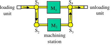
Example. Throughout this paper, the following simple production system will be used to illustrate the design method. This simple production system consists of one loading unit, several transportation switches, two flexible machining stations, one unloading unit, and several conveyor belts (see Figure 3). The flexible machines are able to process a wide range of products. Their capabilities are overlapping, but not identical.
loading unit
machining station
unloading unit
S2 S1
S3 S4 M1
[image:8.612.214.399.216.292.2]M2
Fig. 3. Simple production system example.
The loading unit puts work pieces on the first conveyor belt as prescribed by the order input stream. The transportation switches distribute the work pieces onto the two machines. The machines process the work pieces if they have the requested capabilities. A work piece may only enter a machine if operations requested by the work piece are a subset of the machine's capabilities. After processing, the work pieces are moved to the unloading unit.
The second part of the problem specification defines conditions and goals for the production process. The operation conditions specify the order mix fed into the production system and the spectrum of possible changes and disturbances to the production system during operation. Disturbances are unanticipated breakdowns of components, while changes are induced by the production management and may affect components or the input of the production system. The specification of the production goals describes the expected behaviour of the production system under the specified conditions. Examples of production goals are maximal throughput, minimal investment costs, flexibility with respect to component or order changes, robustness with respect to mechanical or control failures, volume scalability, and reconfigurability of components.
Example. The input stream of the simple production example is an arbitrary mix of different products to be produced. Changes to the production process are not expected and the only possible disturbances are sudden breakdowns of machining stations. The goal of the simple production system is to maximise the throughput and to be robust against station failures.
3.2 Design output
The list of agents defines the global structure of the agent-based control system. It serves as the basis for further design steps specifying the interactions or the agent reasoning (these subsequent steps are not dealt with in this paper).
3.3 Design steps
The design method prescribes two major steps in order to go from the design input to the desired design output.
1. Analysis of decision making – The decisions necessary during the control process are identified and analysed. The result of this step specifies the constraints that any control system supposed to achieve the production goals must satisfy.
2. Identification of agents – The overall structure of the agent-based system is designed. In particular, this step identifies the agents of the system, the decisions for which they are responsible, and the need for interactions between the agents.
Each step of the design method is described in the following sections; section 4 describes the analysis of the decision making, and section 5 presents the agent identification method.
4
Analysis of the Decision Making
The aim of the analysis phase is to develop a model of the control task that can be used as a basis for the identification of the control agents. To achieve this, the analysis step must model the decision making of the control process. A control system controls a production system by monitoring the production process through sensors and by commanding actions to be executed by the actuators of the production components. Because of the discrete nature of most production systems, the operation to be executed by a component can be chosen from a discrete set of possible operations (cf. section 1.2). The analysis step therefore derives decision tasks and decision constraints from the specification of the production control problem and creates a decision model consisting of a set of decision tasks and dependency relations between them. The resulting decision model then serves as a basis for the subsequent design steps.
However, the decision model should only include those decision tasks and constraints that all solutions to the control problem must make or satisfy. Imposing tasks or constraints that do not apply to all potential solutions would limit the space of possibilities in the subsequent design steps and could lead to sub-optimal design decisions. Tasks and constraints that apply to all solutions, though, do not fully determine the control process. The decision model therefore has to be completed in a later design step in order to represent a full control strategy that is capable of achieving the production goals.
execution by an actuator. Although a control system can make (preparatory) decisions that are not immediately executed by a component, any decision must eventually influence an effectoric decision in order to become effective in the production process. It is therefore appropriate to start the analysis with the effectoric decisions. Second, the possible dependencies between control decisions are identified and modelled in a dependency diagram. Third, the decision dependencies are classified with respect to their importance for the production goals and their intensity during operation.
4.1 Identification of effectoric decisions
Effectoric decisions can be identified by looking at the possible choices a component has for its behaviour. There must be more than one alternative in order to require a real decision.
Example. Transportation switch S1 has two alternatives for any work piece reaching it; move the work piece to machine M1 or to the switch S2. Transportation switch S2 has no choice. Theoretically, the switch could delay transportation, but there is no reason to do so. Practically, therefore, switch S2 has no choice but to allow the work piece to proceed immediately.
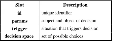
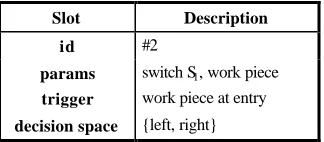
Each identified decision task is characterised according to the following pre-defined schema (Table 1). The parameters of a decision task characterise the subject and object of the decision, i.e., who is deciding about whom; in other words, who performs the action and who is affected by the action. The trigger slot specifies the situation in which the decision becomes necessary. The decision space represents the set of possible choices the component has in that particular situation. Finally, a unique identifier for the decision task facilitates later reference.
Slot Description
id unique identifier
params subject and object of decision
trigger situation that triggers decision
[image:10.612.209.404.462.533.2]decision space set of possible choices
Table 1. Schema for effectoric decisions.
Slot Description
id #2
params switch S1, work piece
trigger work piece at entry
[image:11.612.226.388.139.210.2]decision space {left, right}
Table 2. Example effectoric decision at switch S1.
The set of decision tasks can be represented in a trigger diagram where arrows indicate the temporal sequence of the decisions. An arrow expresses the fact that the physical action enacted because of the first decision eventually or necessarily leads to a situation triggering the second decision. The arrows thus identify all possible causal relationships between decision tasks.
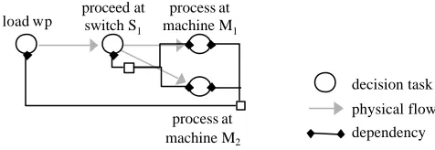
Example. Any decision taken at switch S1 leads to a decision about how to process the work piece at one of the two succeeding machines (because the work piece will either arrive at machine M1 or (via switch S2) at machine M2). In the decision diagram there is therefore one arrow from the decision task of the switch S1 to the decision task of machine M1 and one to the decision task of machine M2 (see Figure 4).
load wp
proceed at switch S1
process at machine M1
process at machine M2
decision task
physical flow
Fig. 4. The trigger diagram for the simple production system.
The trigger diagram illustrates the temporal sequence of decisions (as they are triggered by the physical process) and it can be used as a visual aid in the following analysis (and design) steps.
4.2 Identification of decision dependencies
Example. Transportation switch S1 has to choose one of the exits for each work piece at its entry. Which exit it chooses is irrelevant to the switch. It can move a work piece equally well to either of the exits (as long as they are both free). From the point of view of system performance, however, it is by no means irrelevant onto which exit a work piece is moved. First of all, a work piece may only be moved to a machine that is able to process it. Secondly, the switch determines the distribution of work pieces onto the machines and thus influences the workload on each machine.
A decision task is called dependent on another decision if the former cannot be made (optimally) without some kind of interaction with the latter. Two (or more) decision tasks are called dependent (on each other) if one decision task depends on the other and vice versa. Several researchers have looked at different types of dependencies between tasks in order to derive necessary interactions (e.g., [4,16,25]). For the following analysis, though, it is sufficient to detect that there is some kind of dependency between two decision tasks.
In this domain, the identification of dependencies is usually straightforward (as in the previous example). Many dependencies can be identified simply by studying the trigger diagram since this represents (most of) the effects of the decisions in the production process. Other dependencies can be identified by studying the related decision parameters of the decision tasks. If two tasks refer to the same parameters, it is likely that their decisions will be dependent. In the working example, for instance, the transportation switch and the machine both make decisions about the same work piece and are consequently linked in some way. In some cases, however, it can be quite difficult to identify and prove the dependence between decision tasks. Nevertheless, it is assumed that the designer is able (with acceptable effort) to identify all relevant dependencies in the given production system.
The set of dependencies can also be represented in a diagram. A dependency arrow spans from one decision task to another if and only if the former is dependent on the latter. A dependency arrow is double-headed if and only if the decision tasks are mutually dependent. Dependencies between more than two decision tasks are represented by an arrow with more than one head (on each side).
load wp
proceed at switch S1
process at machine M1
process at machine M2
decision task
physical flow
[image:13.612.184.422.144.226.2]dependency
Fig. 5. The dependency diagram for the simple production system.
4.3 Classification of decision dependencies
Each dependency identified in the decision model is characterised quantitatively according to its intensity and its importance. This allows subsequent design steps to uniformly assess the required interactions between decision tasks. The intensity of a dependency indicates how intense an interaction has to be in order to cope with a dependency. The importance of a dependency tells the designer whether it is necessary to cope with the dependency at all.
Intensity: The intensity of a dependency is uniformly characterised by the degree of the required interaction. The degree of a dependency measures the percentage of a decision space that is affected by the dependency. A choice taken from the affected decision space without interaction with the other decision tasks will affect the system performance.
Example. The transportation switch is fully affected by the dependencies. It can only choose an exit, if the next machine has also been determined. The machines, on the other hand, are only partly affected. They can still decide how to process the work piece once it has reached the machine entry. However, a machine must decide whether or not to process a work piece before the work piece leaves a switch.
Importance: The importance of a dependency can be rated from 0 to 1 by the consequences on the system performance if the dependency is ignored during the control process. If the consequences lead to the non-performance of the production system, the importance is set to 1. If no consequences can be detected, the importance is 0. In between, it is up to the designer to assign an appropriate value. Ideally, the importance measure should be directly linked to a significant performance value (e.g., throughput).
4.4 Output of analysis phase
The result of the analysis is a decision model of the production control tasks. The decision model consists of four parts:
• a list of all decision tasks;
• a trigger diagram;
• a dependency diagram; and
• a classification of each dependency.
The decision model contains all the decisions that any control system must make in order to solve the control problem. However this model is incomplete in the sense that it fails to represent a full control strategy. The missing information has to be completed in subsequent design steps.
5
Identification of the Agents
After analysing the decision making, it is possible to start the design process by identifying the agents of the control system. The agents have to be identified first as they are the basic building blocks of an agent-based control system; they define the overall architecture of the system. Interactions can only be defined by specifying which agent is interacting with which other. At the same time, however, the system architecture also restricts the set of possible interactions, since it specifies the set of agents existing in the control system. It is therefore crucial to identify a set of agents that optimally supports the task of achieving the production goals.
Here an agent is viewed as an interacting decision maker that is able to pro-actively achieve its goals while it is adapting to its dynamic environment. Consequently, it is straightforward to identify an agent by assigning it a set of tasks from the decision model for which it will be solely responsible. Unfortunately, not every assignment of agents to decision tasks will lead to a well-defined agent-based system. For example, if two agents are each responsible for controlling the same actuator, the agents are not fully autonomous (in their behaviour). Only one agent may have full control over the actuator, while the other must request the controlling agent to execute the desired action. Moreover, not every decision network is equally suitable for agent identification. The analysis focused on the decision aspects and deliberately did not take into account any criteria for structuring an agent -based system. It must therefore be possible to reorganise the decision network isomorphically (i.e., without changing the semantics of the decision process) such that it becomes more suitable for agent identification. To this end, section 5.2 describes allowable operations on the decision network.
design process should terminate. If, on the other hand, the applicability of the agent-based approach is confirmed, the assignment of decision tasks to agents can begin. This assignment process is described in section 5.4.
The very first step, however, is to complete the decision network. The analysis only includes those decision tasks in the decision model that all solutions to the control problem must make (cf. section 4). As a consequence, though, the decision model is incomplete. Section 5.1 therefore adds the missing decision aspects such that the completed decision model represents a full control strategy capable of achieving the production goals.
5.1 Completion of the decision network
The decision network is incomplete if any of the decision tasks are not fully specified. According to the decision making model described in section 1.2, a decision task consists of
1. a trigger, specifying the situation that activates the decision; 2. the decision space, specifying the set of possible choices;
3. the decision input, specifying the information necessary to make a decision; and 4. the decision rule, specifying how to make a decision (based on the decision input).
During the analysis process, the designer is only obliged to specify the trigger and the decision space of a decision task. All other slots may be left unspecified. At this point of the design process, however, the decision model must be completed such that all mandatory slots are fully specified. It is therefore necessary to fill in the decision input and decision rule slots (if they have not been specified so far). This can be done in two ways:
1. The decision input only refers to information that can be provided by the sensors of the production system, and the decision rule specifies how to make the decision based on this information.
2. The decision input refers to sensory information and to the result s of other decisions that will be used as a basis for the decision rule to make its decision.
The second option allows additional decision tasks to be introduced that prepare effectoric decisions. The effectoric decision tasks use the non-effectoric decisions to simplify their own computation. Usually, these decisions cover decision aspects that are common to several decision tasks and thus they increase the overall modularity of the decision process.
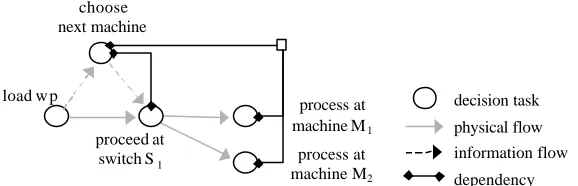
Example. The decision task of transportation switch S1 can be greatly simplified if the next machine is chosen before the work piece reaches the switch S1 (see Figure 6). Based on this abstract decision, the switch can immediately decide whether the work piece must be moved onto the left or right exit. The corresponding dependency diagram is shown in Figure 7.
tasks, of course, requires that the dependency diagram is updated, and is eventually extended by any new dependencies.
load wp
proceed at switch S1
process at machine M1
process at machine M2
decision task
physical flow
information flow choose
[image:16.612.158.449.171.279.2]next machine
Fig. 6. Introduction of abstract decision Choose next machine.
It should be noted that the process of completing the decision model is non-trivial. The decision model must be completed in such a way that the resulting decision making process achieves the production goals. In particular, the decision tasks must take into account the different dependencies that were identified in the analysis phase. The development of a control strategy, however, depends strongly on the kind of production process to be controlled and is therefore application-dependent. It is assumed that the designer is able to find a control strategy that is capable of achieving the production goals under the specified operation conditions.
load w p
proceed at switch S1
process at machine M1
process at machine M2
decision task
physical flow
information flow
dependency choose
next machine
Fig. 7. The extended dependency diagram.
5.2 Operations on the decision network
[image:16.612.160.449.410.503.2]consequently achieves the sam e goal satisfaction as the first. In this regard, the original and the modified decision models are isomorphic.
A decision network is unsuitable for the identification of agents if – according to the criteria for a well-formed agent -based system – a decision task must be assigned to different agents. Such a situation is not permissible because it violates the autonomy and integrity of an agent. In such cases the decision task must be split into different aspects of the original decision that of course share a strong dependency. The different aspects may then be assigned to different agents. There are two ways to split a decision task:
[image:17.612.222.387.284.334.2]• divide splits a decision task into independent aspects of the decision that are considered in parallel (see Figure 8). Each new decision task has the same decision space, but different criteria for making the decision.
Fig. 8. The divide operation.
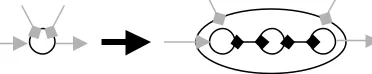
• expand splits a single decision task into subsequent decision (sub)tasks. The result of one decision is the input to another decision task (see Figure 9). Except for the last, every decision subtask formally requires a new decision space and a new decision rule.
Fig. 9. The expand operation.
After each operation, the dependency links must be adjusted accordingly. After a split, a new decision task must inherit any dependency link if the dependency applies to its (sub)task. Each dependency link must be inherited by at least one (sub)task. Additionally, any dependencies between the newly introduced decision tasks must be identified and characterised according to the schema described in section 4.3.
The operations described above may be applied in subsequent design steps in order to make the decision network more suitable for agent identification.
5.3 Assessment of the suitability of an agent-oriented approach
[image:17.612.211.397.417.454.2]appropriate. These criteria do not guarantee that an agent-based approach will be successful, or that it is better than other approaches. However the criteria do rule out applications that are obviously inappropriate.
For an agent-oriented approach to be adequate, the decision network must fulfil three conditions:
1. There are multiple decision tasks.
An agent -based system is always distributed (at least logically). If there is only one decision task, the decision process cannot be distributed. This condition is therefore mandatory.
2. The decision process is dynamic.
A control system that has to make all decisions at once cannot make use of the full power of agent technology. However, this does not rule out the use of agents. The condition is therefore optional. If it is fulfilled, it supports the agent case.
3. The decisions are at least partly independent.
If the decisions are all highly dependent on each other, it is difficult to see how the decision process could be distributed. Every decision task would communicate heavily with every other decision task. This condition is therefore mandatory. However, the condition is not "black and white". No application has purely dependent or purely independent decision tasks. How much dependence is acceptable depends on the particular agent techniques used and is therefore ultimately left to the designer.
If the decision network scores low on the above conditions, the designer may still be able to transform the decision network into a more suitable form by using the allowable operations described in section 5.2. If, after extensive improvements, the decision network still scores low on the above conditions, the control system should not be developed as a (pure) agent-based system. This does not imply that it is impossible to use an agent -based approach. Rather it only suggests that the designer should reflect very carefully about what other (possibly application-dependent) reasons are in favour of agent technology and why it is not more appropriate to use other approaches.
Example. Despite its simplicity, the simple production example scores high on the necessary conditions. First, the decision network has more than one decision task. Second, the decision process is dynamic. There is a constant flow of (different) work pieces into the system that must be distributed to the machines depending on their current availability. Third, the decision tasks are partly independent, even though they all relate to the same task: distributing work pieces onto two machines.
5.4 Clustering of decision tasks
However, in order to create a well-formed agent-based system, the resulting clusters should fulfil the following two modularity criteria (cf. also [24]):
1. The decision tasks of a cluster should be coherent.
2. There should be no strong coupling (dependence) between any two clusters.
Strong cohesion and low coupling for clusters of decision tasks can be achieved in three ways:
• interface cohesion
All decision tasks in one cluster access the same sensors and effectors, whereas decision tasks in different clusters do not access the same physical interface.
• responsibility cohesion
The responsibility for a local state of a production object (e.g., a machine or work piece) is assigned to at most one cluster. Decision tasks in another cluster may not directly alter this state.
• low interactive coupling
There is no strong coupling (i.e., dependence) between the decision tasks of different clusters.
Note that the above criteria can be in conflict. It is a design decision to resolve a conflict by preferring one particular criterion. Moreover, it may not be possible to cluster the decision network created in the analysis phase according to any of the above criteria. In such cases, the network first has to be transformed by the operations described in section 5.2 before the clustering can be performed successfully.
Once the decision network has a suitable form for clustering, the following strategies can be employed to cluster the decision model:
• Interface clustering
Cluster decision tasks that access the same physical interfaces. Several interfaces may end up in one cluster, but an interface should never belong to more than one cluster. In case of a conflict, a decision task can be split and the sub-decisions assigned to different clusters.
• Data / State clustering
Cluster decision tasks which access and change the same logical data or status of the production system (e.g., the work piece status).
• Dependence clustering
Cluster decision tasks which have a strong dependence.
• No bottleneck clustering
Distribute decision tasks such that the system has no bottlenecks.
Example. In the decision model of the simple production system, agents can be identified in a straightforward fashion. First of all, a switch agent and a machine agent are associated with each switch or machine respectively and they become responsible for the decision task associated with the particular component. Likewise, a loading agent is assigned to the loader and its decision task. All these agents are static.
supposed to be processed. This decision task is therefore divided into several aspects: A decision aspect for each machine and one for the work piece. The work piece agent responsible for this decision task is created by the loading agent when the corresponding work piece is put on the first conveyor belt. This work piece agent then interacts with the machine agents in order to choose the next machine and informs the switch agent of switch S1 about the next goal machine.
As with the modularity criteria, the above strategies can be in conflict too. Again it is a design decision about which strategy should be preferred when there is a conflict.
Clustering strategies (in combination with the allowable operations) are applied to the decision network until a satisfactory partitioning has been found. Even though the modularity criteria indicate the quality of the partitioning, it is ultimately left to the designer to decide whether the achieved quality is sufficient.
5.5 Output of the agent identification phase
The results of the first design step are twofold. First of all, an assessment of the decision model created in the analysis phase indicates the suitability of an agent-oriented approach to the particular production control problem. Secondly, in cases where the suitability is confirmed, the design step identifies a list of agents, each associated with a subset of the decision tasks. The agents are solely responsible for the execution of their decision tasks, but depend on other agents whenever decision dependencies exist between decision tasks that are assigned to different agents.
6
Conclusions and Future Work
This paper has presented a design method for the identification of agents in production control systems. The design method consists of two main steps. First, the decision making necessary to control the given production system is analysed. This step identifies the decisions necessary to achieve the production goals and the dependencies between these decisions. Second, the necessary agents to control the production system are identified. This step transforms the decision network into a more suitable form for an agent-oriented approach, assesses the appropriateness of an agent-oriented approach and identifies the agents as well as the required interactions. The result of the method is a set of agents associated with control responsibilities and dependencies.
step provides criteria for re-organising and clustering the decision network in order to identify agents. Finally, the design method provides criteria for assessing the suitability of an agent-oriented approach for the given production control problem. In summary, the design method fulfils both requirements put forward in section 1.1. Thus it allows an engineer with no prior experience in agent technology to successfully apply the design method to a production control problem.
The next stage of this work is to complete the design method by dealing with the interactions that occur between the agents. These interactions stem from the dependencies that exist between the agents’ decision making responsibilities. To this end, many interaction formalisms and design approaches have been proposed to date. However none of these approaches addresses the question of how protocols are derived from a problem description.
References
1. B. Burmeister: “Models and Methodology for Agent-Oriented Analysis and Design”. In K. Fischer (ed.): Working Notes of the KI'96 Workshop on Agent-Oriented Programming and Distributed Systems, pages 7 – 17. Document D-96-06. DFKI: Saarbrücken, Germany, 1996.
2. S. Bussmann, D.C. McFarlane: ”Rationales for Holonic Manufacturing Control”. In Proc. of Second Int. Workshop on Intelligent Manufacturing Systems, pages 177 – 184, Leuven, Belgium, 1999.
3. S. Bussmann, K. Schild: "Self-Organizing Manufacturing Control: An Industrial Application of Agent Technology". In Proc. of the Fourth Int. Conf. on Multi-Agent Systems, pages 87 – 94, Boston, MA, USA, 2000.
4. K.S. Decker: Environmental Centered Analysis and Design of Coordination Mechanisms. PhD Thesis, University of Massachusetts, MA, USA, 1992.
5. M. Wood, S.A. DeLoach: "An Overview of the Multiagent Systems Engineering Methodology". In this volume.
6. R.G. Fichman, C.F. Kemerer: "Object-Oriented and conventional analysis and design methodologies – comparison and critique". In IEEE Computer, Vol. 25, No. 10, pages 22 – 39, 1992.
7. N. Glaser: “The CoMoMAS Methodology and Environment for Multi-Agent System Development”. In C. Zhang, D. Lukose (eds.), Multi-Agent Systems – Methodologies and Applications, LNAI 1286, pages 1 – 16. Springer-Verlag: Berlin, Germany, 1997.
8. H. Hußmann: Formal Foundations for Software Engineering Methods. LNCS 1322, Springer-Verlag: Berlin, Germany, 1997.
9. C.A. Iglesias, M. Garrijo, J.C. Gonzalez: "A survey of agent-oriented methodologies". In
Pre-Proc. of the 5th Int. Workshop on Agent Theories, Architectures and Languages, Paris,
France, 1998.
10. C. A. Iglesias, M. Garijo, J.C. Gonzalez, J.R. Velasco: “Analysis and Design of Multiagent Systems Using MAS-CommonKADS”. In M.P. Singh, A. Rao, M.J. Wooldridge (eds.),
Intelligent Agents IV (ATAL'97), LNAI 1365, pages 314 – 327. Springer-Verlag: Berlin, Germany, 1998.
11. I. Jacobson: Object-Oriented Software Engineering: A Use Case Driven Approach. Addison-Wesley, 1992.
13. E.A. Kendall: "Agent Software Engineering with Role Modelling". In this volume.
14. D. Kinny, M. Georgeff: "Modelling and Design of Multi-Agent Systems". In J.P. Müller, M.J. Wooldridge, N.R. Jennings (eds.), Intelligent Agents III (ATAL'96), LNAI 1193, pages 1 – 20. Springer-Verlag: Berlin, Germany, 1997.
15. J. Lind: MASSIVE: Software Engineering for Multiagent Systems. PhD thesis, University of Saarbrücken, Germany, 1999.
16. F. von Martial: Coordinating Plans of Autonomous Agents, LNAI 610. Springer-Verlag: Berlin, Germany, 1992.
17. B. Moulin, M. Brassard: "A Scenario-Based Design Method and an Environment for the Development of Multiagent Systems". In C. Zhang, D. Lukose (eds.), Distributed Artificial Intelligence – Architecture and Modelling, LNAI 1087, pages 216 – 232. Springer-Verlag: Berlin, Germany, 1996.
18. A. Omicini: "SODA: Societies and Infrastructure in the Analysis and Design of Agent-based Systems". In this volume.
19. H.V.D. Parunak: "Manufacturing Experience with the Contract Net". In M.N. Huhns (ed.),
Distributed Artificial Intelligence, pages 285 – 310. Pitman: London, UK, 1987.
20. V. Parunak, J. Sauter, S. Clark: “Toward the Specification and Design of Industrial Synthetic Ecosystems”. In M.P. Singh, A. Rao, M.J. Wooldridge (eds.), Intelligent Agents IV (ATAL'97), LNAI 1365, pages 45 – 59. Springer-Verlag: Berlin, Germany, 1998.
21. J. Rumbaugh, M. Blaha, W. Premerlani, F. Eddy, W. Lorensen: Object-Oriented Modeling and Design. Prentice-Hall: Englewood Cliffs, NJ, USA, 1991.
22. G. Schreiber, B.J. Wielinga, R. de Hoog, H. Akkermans, W. Van de Velde: "CommonKADS: A comprehensive methodology for KBS development". In IEEE Expert, Vol. 9, No. 6, pages 28 – 37, 1994.
23. M. Wooldridge, N.R. Jennings, D. Kinny: "The Gaia Methodology for Agent-Oriented Analysis and Design". In Autonomous Agents and Multi-Agent Systems, Vol. 3, No. 3, pages 285 – 312, 2000.
24. E. Yourdon, L.L. Constantine: Structured Design. Prentice Hall: Englewood Cliffs, NJ, USA, 1979.
25. E.S.K. Yu, J. Mylopoulos: "Understanding the 'Why' in Software Process Modelling, Analysis, and Design". In Proc. of the 16th Int. Conf. on Software Engineering. Sorrento,