warwick.ac.uk/lib-publications
Original citation:
Kourra, Nadia, Warnett, Jason, Attridge, Alex, Dahnel, Aishah Najiah, Ascroft, Helen, Barnes, Stuart and Williams, M. A. (Mark A.). (2016) A metrological inspection method using micro-CT for the analysis of drilled holes in CFRP and titanium stacks. International Journal of Advanced Manufacturing Technology . pp. 1-11.
Permanent WRAP URL:
http://wrap.warwick.ac.uk/79065
Copyright and reuse:
The Warwick Research Archive Portal (WRAP) makes this work of researchers of the University of Warwick available open access under the following conditions.
This article is made available under the Creative Commons Attribution 4.0 International license (CC BY 4.0) and may be reused according to the conditions of the license. For more details see: http://creativecommons.org/licenses/by/4.0/
A note on versions:
The version presented in WRAP is the published version, or, version of record, and may be cited as it appears here.
DOI 10.1007/s00170-016-8691-4
ORIGINAL ARTICLE
A metrological inspection method using micro-CT
for the analysis of drilled holes in CFRP and titanium stacks
Nadia Kourra1·Jason M. Warnett1·Alex Attridge1·Aishah Dahnel1· Helen Ascroft1·Stuart Barnes1·Mark A. Williams1
Received: 4 December 2015 / Accepted: 27 March 2016
© The Author(s) 2016. This article is published with open access at Springerlink.com
Abstract This paper demonstrates a novel method that combines X-ray computed tomography (CT) and image pro-cessing for investigating two materials with significantly different densities. CT is increasingly used in industrial applications of inspecting materials and defects. The limita-tions of the system and data reconstruction are continuously researched so as to improve the quality of the results. One of the most common issues in CT is beam hardening, fre-quently experienced in multi-material scanning. The mate-rials examined to demonstrate the method are carbon fibre reinforced polymers (CFRP) and titanium alloy Ti6Al4V, often used in combination in industry to optimise the weight to strength ratio. The assembly of the materials is usually achieved by bolting and riveting, which requires drilling through the two materials together. The machining of these materials is difficult due to their higher specific properties and as a result tool wear is always an issue. CFRPs proper-ties depend on the nature, orientation and bond of the fibres and as a result drilling affects their service life. The results of the method ensure the quality of the drilled holes by measuring the variation of the maximum diameter, circular-ity, positioning of the hole and an examining the entrance delamination and exit burrs by image processing.
Keywords Metrology·Computed tomography·Image processing·CFRP·Ti6Al4V·Drilling·Non-destructive evaluation·Non- contact inspection
Nadia Kourra
1 IMC, WMG, The University of Warwick, Coventry,
CV4 7AL, UK
1 Introduction
X-ray computed tomography (CT) utilises a series of radio-graphs that are reconstructed into a 3D model that provides data of the outer surface and structure of the scanned speci-men as well as the inner structure and any potential defects. The pixels of the radiographs have different grey values based on the amount of radiation reaching the detector after penetrating the scanned object (Fig.1). The reconstruction of numerous radiographs collected from a 360◦rotation of the part with filtered back projection (FBP) converts the 2D pixels to 3D voxels that digitally rebuild the part. The voxels represent the entire volume rather than an externally observ-able area and can be exported for analysis. Variation in grey values within the 3D volume can demonstrate differences of density, the existence of either material or background or air and provide information of a defect such as porosity or cracks [1–5].
CT data is affected by many different variables that can influence its quality such as beam hardening that causes lin-ear shadowing around the 3D reconstruction of the part or produces different grey values in homogeneous materials. This issue is caused by the nature of the polychromatic x-ray beam spectrum and the attenuation of the radiation by the part. Polychromatic radiation includes a spectrum of dif-ferent radiations up to the desirable radiation energy. The lower energy radiation is absorbed by the more dense mate-rials, and it does not reach the detector while the higher energy radiation is able to penetrate the specimen. The nor-malisation of the data in the reconstruction process causes the creation of this phantoms, and it is a common issue in high energy scans and in multi-material scans [1].
Fig. 1 The grey value of each pixel demonstrates the attenuation level of x-rays from matter
require extensive analysis other than reducing systematic CT errors/artefacts while as a metrological tool, further procedures are required to be followed to overcome and pos-sibly eliminate any issues that can affect the precision of the data. These issues can possibly affect the CT data caused by bi-directional repeatability of the system, radial run-out errors, the detector tilt and type, size and movement of the x-ray spot during the scan. The effect of these issues can be reduced by following the recommendations provided in VDI/VDE 2630 Part 1.4, a guide to obtain dimensional mea-surements through CT. In order to eliminate absolute scale errors in CT measurements that are caused by imprecise voxel size, nominal/actual comparison between the scanned data and a reference measurement is required according to these guidelines. This comparison can reduce the systematic measurement error from 1 to 0.2 % [1–4,6–12].
This paper demonstrates a method of CT scanning and analysing multi-material parts that are affected by the lim-itations of a CT system and they are suffering from beam hardening and noise. In order to develop and demonstrate the capabilities of this method, multi-material samples were examined. The samples are combining carbon fibre rein-forced polymers (CFRPs) and titanium alloy which are materials with distinctively different densities.
1.1 Examined materials
Composite materials are often favoured over traditional materials for structural applications due to their higher spe-cific properties of strength and stiffness, leading to weight reduction of the entire structure and reduction of energy consumption. For this reason, composites such as CFRPs are increasingly being utilised in aerospace, navel, space and automotive applications. Similarly, titanium and its alloys are often used because of their high strength to weight ratio, compressive and tensile strength at high temperature,
low density, corrosion and erosion resistance, fatigue resis-tance and low modulus of elasticity. These materials are frequently combined by bolting and riveting to optimise the weight to strength ratio [13,14].
Numerous studies examine the drilling of CFRPs as machining difficulties are often encountered. Composite materials are anisotropic, non-homogenous and heat sensi-tive, while their machining behaviour depends on diverse reinforcement and the properties of their matrix. CFRPs achieve their mechanical and structural properties from the nature, orientation and bond of fibres that are arranged in flat panels, sheets or woven structures [13–21]. Any machining that breaks the fibres influences the properties and service life of the part. Many studies have examined different machining processes, tools, set-ups and settings, and it can be concluded that the formation of defects and high wear of the cutting tools are caused by the non-optimum combination of process parameters, tool geometry and cutting tool material [13,22–26].
Wherever possible, composites are produced with near net shape processes to avoid damages caused by machin-ing; however, drilling is a secondary machining process that is difficult to avoid since it is required to install mechani-cal fasteners. The drilling process can cause fragmentations, burrs, interlaminar cracks, interfacial de-bounding, thermal damages and fibre pull-outs. A high percentage of part rejections are due to poor hole quality [13–19,22,27,28]. The examination of the holes after their production is under-taken by destructive and non-destructive methods, to better understanding the effects of the machining processes and the way that they affect the service life of the part. Dif-ferent machining processes are continually being studied to improve the outcomes [13,17–19,22–28].
The effect of tool characteristics such as geometry, mate-rial and type have been considered in several studies with the results indicating that smaller contact length between drill and hole and a smaller chisel size are beneficial. The other important aspects of drilling CFRPs are tool thrust and torque, feed rate and cutting speed. The defects are attributed to the brittle nature of the fibres that are deformed and cut by brittle fracture during machining which often results in uncut fibres and rough surface finish. Tool wear and thrust forces contribute to the formation of defects while low cutting speeds and high feed rate, such as less than 50 m/min and more than 0.1 mm/rev respectively, cause fibre breakage, pull-outs, cracks and delamination. The machining of CFRPs is also affected by the low tem-perature strength of the matrix that is typically less than 180◦C and temperatures higher than this result in material softening, degradation and poor surface finish [29–31].
[image:3.595.51.290.58.224.2]alloys introduces more challenges due to its higher specific properties, significantly formation and tool wear. Concen-trated heat at the cutting edges results from low thermal conductivity of the material. Temperatures can rise to over 1000◦C in dry conditions resulting in a chemical reaction with the tool material leading to tool weakening and fail-ure, while the titanium maintains its properties of hardness and strength. As a result, the machining of titanium typi-cally incurs high machining cost with high tool wear, tool life is decreased by chipping, and burrs are introduced to both entrance and exit surfaces of the holes. Thrust force, tool wear and the increase of the feed rate during drilling affect the formation and size of burrs, which may result in inaccuracies and assembly errors [14,32–36].
The results of different drilling methods such as ultrasonic-assisted drilling (UAD) have been compared to conventional drilling (CD) in order to identify optimum set-ting. The utilisation of UAD in the drilling of CFRP has been shown to improve the quality of the holes, while the results for its application on titanium alloys are more varied, with some studies demonstrating different results for dif-ferent alloys and others showing benefits with lower thrust forces. It is generally accepted that UAD increases tool life, which affects the quality of the holes, due to less titanium adhesion on the cutting edges and less edge chipping which corresponds to reduced titanium burr [36–39]. The process relies on the application of ultrasonic vibrations of 2–20μm and 20–45 kHz amplitude and frequency, respectively, which is superimposed in the feed direction of the cut-ting edges during drilling. The CFRP results of this method demonstrate lower thrust forces, lower surface roughness, smaller delamination and improved circularity compared to CD [38]. Nevertheless, higher cutting temperatures are observed during UAD of CFRPs and titanium alloys indi-vidually which are proportional to the ultrasonic amplitude due to energy consumption as the tool vibrates. Measure-ments of drilled through stacks of CFRP/Ti6Al4V, produced by UAD and CD with a three-point bore micrometre has shown more consistent and closer to nominal diameters for UAD [37–40]. The application of UAD demonstrates promising results and further investigation is required, while the combination of CFRPs and titanium alloys introduces
unforeseen challenges that depend on the nature of the specific combination of CFRP and titanium alloy.
1.2 Quality inspections and computed tomography
The investigations of different machining processes and combinations of different materials usually apply destruc-tive methods by cutting the part to examine it. As a result of these examinations, part of the specimen is destroyed and some potentially useful data is lost. Optical inspections with microscopes while non-destructive can only provide data of the entrance and exit surfaces of the drilled holes and surface roughness examinations provide limited data of specific points.
The most common examination methods used in the investigation of defects of CFRPs are radiography, ultra-sonics, and eddy-currents after optical examinations and destructive test. Optical techniques used in the past include infra-red thermography while the specimen is under load, eddy currents with special probes, pulse echo ultrason-ics, digital image analysis, shadow moire laser and guided waves [18,22,41–47]. These methods were used to identify the orientation of fibres, defects and their type, fibre frac-tions resin-rich zones, impact damages, the extent of hidden delamination and the growth of fatigue damages during tests. Each method has its limitations, and they are chosen according to the application. All of these methods provide limited data with constrained accuracy which is subject to human error, and they are unable to provide data for the entire specimen. The inspection of titanium also includes destructive methods that are then optically examined with microscopes and non-destructive methods such as radiogra-phy, ultrasonics and eddy currents with similar limitations as previously discussed [18,22,41–47].
[image:4.595.53.543.622.716.2]The combined issues caused by drilling of these materials require the identification of the optimum machining settings for the specific combination of materials. This study exam-ines and compares drilled holes produced by UAD and CD of CFRPs and titanium alloy Ti6Al4V stack using CT and image processing. The holes examined in this case study are part of an investigation to identify optimum drilling meth-ods and settings that could benefit an industrial production
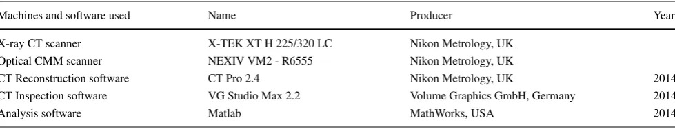
Table 1 Machines and software used in this method
Machines and software used Name Producer Year
X-ray CT scanner X-TEK XT H 225/320 LC Nikon Metrology, UK Optical CMM scanner NEXIV VM2 - R6555 Nikon Metrology, UK
CT Reconstruction software CT Pro 2.4 Nikon Metrology, UK 2014
CT Inspection software VG Studio Max 2.2 Volume Graphics GmbH, Germany 2014
line. The method used is based on an investigation of CFRP drilled holes utilising CT and image processing [48]. The combination of different materials and the significant differ-ence of their atomic mass and structure introduce issues to the CT examination and image processing analysis that are identified and overcome by this method.
2 Method
The method presented here was developed to examine dif-ferent materials with significantly difdif-ferent atomic mass and structure. A stack of CFRP and Ti6Al4V was used to demonstrate the results of the method. The examined sam-ples are test results of two different machining processes, and they are part of an investigation to identify the optimum drilling settings. The CT examination of the two drilling methods, CD and UAD, can provide information about the quality of the holes and assists in the identification of the optimum settings for this combination of materials. The evaluation of the quality of the holes is based on the internal damage of the materials, the circularity and centre deviation of the entire hole. The image processing analysis is based on a method developed to evaluate the quality of CFRP holes [5,48]. All of the scanners and software packages used are provided in Table1.
2.1 Preparation of the parts
Both machining processes, CD and UAD, were performed on CFRP/Ti6aAl4V stacks with the same machine, Ultra-sonic 65 monoBLOCK, DMG with an ultraUltra-sonic actuator built into the tool holder, as shown in Fig. 2. The two materials were joined together with Hysol 9492 prior to the machining. The thickness of the different materials was 4 mm. The cutting speed and feed rate were constant at
Fig. 2 Experimental drilling set-up of conventional and ultrasonic drilling
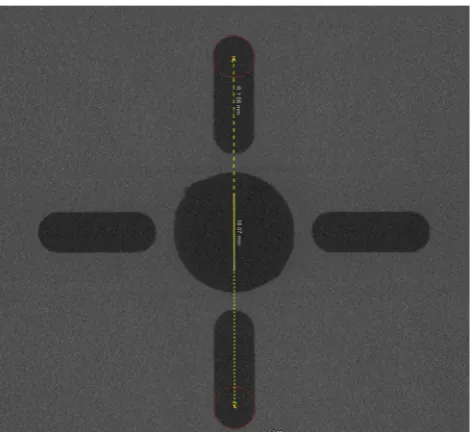
Fig. 3 Voxel rescaling according to CMM measurements. The centre to centre distance of the prescribed circlesshown are scaled to the actual canter to centre distance measured by optical CMM
50 m/min and 0.05 mm/rev, respectively. The drilling took place with a reground tungsten carbide 2-flute twist drill with point angle of 140◦ and a helix angle of 30◦. The diameter of the tool was 6.12 mm and 50 holes for each technique were drilled. In order to compare the two tech-niques and examine the effect of the tool wear into the quality of the results, one hole was examined for every 10 drilled holes, 5 holes per technique. The drilling initiated with CFRP material on the top and as a result the entrance surface is CFRP while the exit surface is Ti6Al4V. The cool-ing method used for both techniques was via the external
[image:5.595.308.544.58.274.2] [image:5.595.307.543.511.677.2] [image:5.595.52.289.524.688.2]Table 2 Selected CT settings
CT settings
Voltage (kV) 215
Power (W) 6
Exposure Time (s) 4
Gain (dB) 18
Voxel size (μm) 17.5
X-ray filtration (mm) 0.675
X-ray filtration Materia Tin
application of a standard water-based cutting fluid. The UAD holes were produced with maximum oscillation of 2.6μm and the frequency of the vibrations was 42.7 kHz. The positioning of each hole according to the manufacturer is≤8μm.
Four slots were produced prior to the drilling of each hole so as to mark the centre of the hole and the orienta-tion of the part during the drilling, as shown in Fig.3, and they were used for voxel rescaling during the image pro-cessing. The tool used for the production of the slots was a 2-mm-diameter Q-coat tungsten carbide slot drill with cut-ting speed 18.833 m/s, cross feed 0.042 m/s and depth feed 0.002 m/s. Their depth is 0.7 mm and length 8 mm.
2.2 CT acquisition and reconstruction
CT scanning depends on a series of variables that are selected based on the scanned material, the capabilities of the CT system and the required resolution. In order to achieve optimum results that can be used for a metrologi-cal investigation, VDI/VDE 2630 Part 1.4 guidelines were followed. The CT scanning set-up is shown in Fig.4.
Initially, the stacks of CFRP/Ti6Al4V were scanned prior to the drilling to ensure the quality of the joining with Hysol 9492. Then, the part was scanned after the drilling to investi-gate the quality of the holes. The settings selected are shown
in Table 2 and the positioning of the parts was selected for maximum magnification resulting in a voxel size and resolution of 17.5μm.
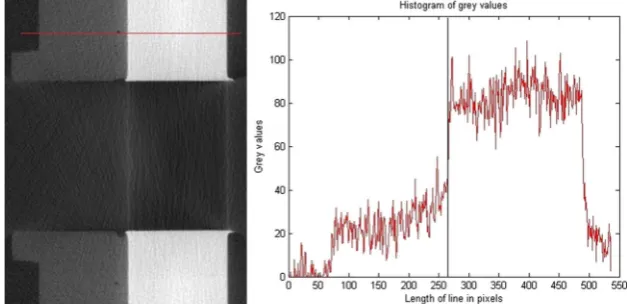
The combination of the two materials with distinctly dif-ferent atomic masses cause one of the most common CT artefacts, which is beam hardening. Figure5demonstrates the effect of beam hardening and noise caused by the scan-ning of the two materials with the histogram providing the amount of grey values in the length of the red line. The black line in the histogram demonstrates the point where the mate-rials intersect. The areas that are affected by these artefacts are around the titanium alloy. Prior to the reconstruction of the 2D images, a beam hardening reduction algorithm with offset was used to minimise the effect of the artefacts in the model [49].
After the reconstruction of the images to a 3D model, each hole was aligned based on the slots produced prior to the drilling to the intended centre of the hole. Each slot was measured with optical CMM and the distances between the slots were later used for voxel rescaling performed in VG Studio Max 2.2, as shown in Fig.3. Each CMM measure-ment was repeated five times to improve the accuracy and reduce the uncertainty of the results. The voxel rescaling took place prior to the image processing during the align-ment of the part according to the slots that demonstrate the indented machining axis. The aligned model was then exported as a 2D DICOM image stack for analysis, where each slice is one voxel thick.
2.3 Image processing
The DICOM images were exported by the visualisation soft-ware VG Studio Max 2.2 for image analysis in MATLAB. The Otsu method was used to identify the required thresh-old to convert the grey images to binary and the Hough transform was used to identify the lines of the markings and calculate the ideal centre [50]. The Wiener filter was also used to reduce the noise introduced by the residual beam
[image:6.595.230.544.561.713.2]Fig. 6 Examination of the join show extreme porosity. Pores are represented asblackand glass particles aswhite
hardening. It is based on statistical methods to identify and remove noise by considering the neighbourhood of each pixel, removing abhorrent values. Removal of noise in this manner is edge preserving. The Canny method was used to identify the edges that form the circle and a circular Hough transform was used to identify the circles and calculate the actual radius.
Initially, an image close to the entrance surface was selected and the slots were used as markings to identify the ideal centre of the hole. This measure was applied to all images that were used to calculate the maximum and
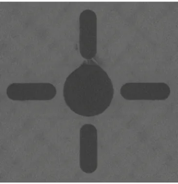
[image:7.595.77.262.59.248.2]Fig. 7 The slots are close to the hole and may have affected the entrance delamination
Table 3 Tolerances when drilling CFRPs
Tolerances type Symbol Tolerances values (mm)
Diameter 6.120 + 0.075
Circularity 0 + 0.200
Positioning 0±0.075
minimum radius, maximum and minimum diameter, circu-larity, perimeter and positioning of the circle shown in every slide. The maximum and minimum radii were found by cal-culating the distance between the ideal centre and the edges of the circle. The maximum and minimum diameters were calculated by two points that intersect the circle edge from the line that passes through the ideal centre. The circularity was calculated as the difference between the maximum and minimum radii which agrees with ASME Y 14.5M 1994 [51]. The circumference of the hole can indicate the extent of delamination instead of the maximum that is identified by the calculations of diameter and radius. However, due to the defect, the shape of the hole can become abstract and as a result it is called perimeter. The perimeter of each hole was calculated by the points of the edge. The positioning of the hole was calculated as the absolute difference between the ideal centre and the actual centre of the circle identified by the actual centre of the circle determined by the circular Hough transform.
3 Results and discussion
Initially,the joining of the two materials was visually exam-ined prior to the drilling, as shown in Fig.6. The joining of the materials was achieved by Hysol 9492 and includes glass particles with 0.3 mm diameter to ensure homoge-nous thickness. The results show significant porosity in the join and the glass particles are easily identifiable from their higher density in comparison to the surrounding material. This joining was intended to bond the two materials together after the drilling for the CT investigation since no other fastening method is used.
[image:7.595.306.544.73.139.2] [image:7.595.78.261.463.652.2]The image analysis provided data on the maximum diam-eter and radius, the circularity, perimdiam-eter and positioning, that were used to compare the two different drilling meth-ods and the effect of the tool wear throughout the drilling of 50 holes. It also demonstrates whether the tolerances are met that determine the quality acceptance or failure of the part. The tolerances provided in Table 3 are an example of typical tolerances required from the aerospace industry for CFRPs [48]. The differences between the two materials are conspicuous with the results improving for the titanium alloy for both drilling methods especially in the latest holes when the tool wear affects the CFRP material greater than
0 1 2 3 4 5 6 7 8 9
2 4 6 8 10 12 14
Distance from front surface (mm) Magn.
(mm)
Maximum Diameter and Maximum Radius
MD CD10 MR CD10 MD UAD10 MR UAD10
CFRP Ti6Al4V
Join
(a)
0 1 2 3 4 5 6 7 8 9
2 4 6 8 10 12 14
Distance from front surface (mm) Magn.
(mm)
Maximum Diameter and Maximum Radius
MD CD50 MR CD50 MD UAD50 MR UAD50
CFRP Ti6Al4V
Join
(b)
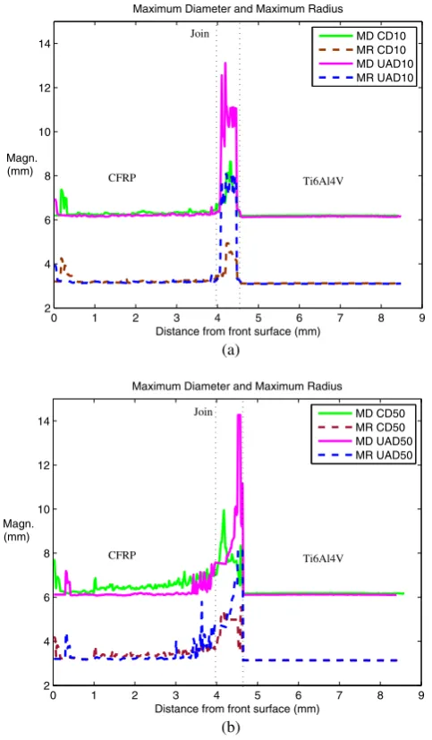
Fig. 8 Maximum diameter and maximum radius per slide. The dif-ferent sections of the hole are identified as CFRP, Join and Ti6Al4V. Results for (a) 10th drilled hole and (b) 50th drilled hole
Ti6Al4V. The greatest difference in the results are in the joins that are affected by severe porosity. The results of the maximum diameter and radius of the first and last inspected holes are shown in Fig.8a, b. Hole nos. 10 and 50 for each technique demonstrate the difference of distribution that is located in the joins due to the porosity and discontinuities of the joining material. In order to examine the results of the two materials better, the following figures do not include the values from the area of the joins.
The results of the first pair of holes, CD10 and UAD10, shown in Fig. 9a indicate that the maximum radius and diameter of both materials are more consistent and closer to tolerance with UAD. The maximum values of maximum diameter and radius for CFRP are 6.432 and 3.365 mm for CD and 6.293 and 3.209 mm for UAD, ignoring the entrance delamination and the joining session, the maxi-mum diameter for the Ti6Al4V is 6.204 mm for CD and 6.163 mm for UAD, the maximum radius of Ti6Al4V is stable and does not exceed 3.125 mm. Even so, both holes would have failed inspection since the CFRP part of the holes exceed the required tolerance of 6.195 mm diame-ter. Figure9b shows the results of circularity. Overall, the results are similar for the two drilling methods with the Ti6Al4V circularity varied around 0.055 mm and the CFRP circularity varied just below the tolerance of 0.200 mm except the few random peaks reaching 0.504 mm for UAD and 0.207 mm for CD. The maximum value of circular-ity for the CFRP is 0.273 mm for CD and 0.0239 mm for UAD. The circularity of Ti6Al4V is stable for both drilling methods and it does not exceed 0.080 mm. Perime-ter results of the first holes, CD and UAD 10, also indicate that UAD provides slightly more stable results, as shown in Fig. 9c. The difference between the two techniques is not significant and show that the perimeter of the UAD hole does not exceed 26.149 mm for CFRP and 24.699 mm for Ti6Al4V while the results of the CD hole demon-strate that the perimeter reaches 27.871 mm for the CFRP and 24.899 mm for the Ti6Al4V. The positioning of the holes, shown in Fig.9d, fail to meet the tolerance target of 0.075 mm and reaches 0.237 mm for CD and 0.241 mm for UAD. The results of both drilling methods give similar read-ings and CFRP positioning is worse than the positioning of Ti6Al4V.
[image:8.595.50.292.229.643.2]0 1 2 3 4 5 6 7 8 9 2
3 4 5 6 7 8 9
Distance from front surface (mm) Magn.
(mm)
Maximum Diameter and Maximum Radius
MD CD10 MR CD10 MD UAD10 MR UAD10 Tolerance
(a)
0 1 2 3 4 5 6 7 8 9
0 0.5 1.0 1.5 2.0 2.5 3.0
Distance from front surface (mm) Magn.
(mm)
Circularity
CD10 UAD10 Tolerance
(b)
0 1 2 3 4 5 6 7 8 9
25 30 35 40 45
Distance from front surface (mm) Magn.
(mm)
Perimeter
CD10 UAD10
(c)
(d)
Fig. 9 The results of the first holes for both CD and UAD of the 10th holes. The results shown are per slice and the entrance surface is located at 0 mm and exit surface at 8.4 mm. Tolerances are given for diameter, circularity and positioning. Panelashows the maximum
diameter and radius,bshows the circularity results,cshow the results for the perimeters and (d) shows the positioning with a zoom in area to demonstrating the difference between the two materials
few high values exceeding for the CFRP and indicate exit delamination with a radius reaching 5.784 mm. Ti6Al4V radius is in the steady range of 3.130 mm. The circularity results shown in Fig.10b show CFRP results slightly fail-ing to meet the tolerance with few worse exceptions close to the entrance and exit CFRP surfaces reaching 1.407 mm. Ti6Al4V results show a better picture for both drilling tech-niques with the circularity stable close to 0.098 mm. The
[image:9.595.301.542.57.484.2]0 1 2 3 4 5 6 7 8 9 2
3 4 5 6 7 8 9
Distance from front surface (mm) Magn.
(mm)
Maximum Diameter and Maximum Radius
MD CD50 MR CD50 MD UAD50 MR UAD50 Tolerance
(a)
0 1 2 3 4 5 6 7 8 9
0 0.5 1.0 1.5 2.0 2.5 3.0
Distance from front surface (mm) Magn.
(mm)
Circularity
CD50 UAD50 Tolerance
(b)
0 1 2 3 4 5 6 7 8 9
25 30 35 40 45
Distance from front surface (mm) Perimeter
CD50 UAD50
Magn. (mm)
[image:10.595.202.528.57.488.2](c)
(d)
Fig. 10 The results of the last holes for both CD and UAD of the 50th holes. The results shown are per slice and the entrance surface is located at 0 mm and exit surface at 8.4 mm. Tolerances are given for diameter, circularity and positioning. Panel a shows
maximum diameter and radius, b shows the circularity results, cshow the results for the perimeters and (d) shows the positioning with a zoom in area to demonstrating the difference between the two materials
4 Conclusions
This paper demonstrates a new method of multi-material CT scans and analysing them with image processing. CT scanning of two or more materials with significantly differ-ent atomic mass and structure can cause beam hardening and noise that affects image quality. The method combines physical filtration to reduce the spectrum of polychromatic radiation, alongside beam hardening reduction algorithms
machining processes that were previously inaccessible with any other non-destructive method.
The parameters considered were maximum diameter and radius, circularity, perimeter and positioning of each hole. The joining of the two materials with Hysol 9492 contained porosity that could adversely affect the drilling process and the resultant hole dimension. The joining method was kept constant between all parts to ensure similar initial conditions as found in initial scans prior to drilling. The results demon-strate that Ti6Al4V is more resilient to the drilling process with the aforementioned parameters remaining within tol-erance. The CFRP results are within tolerance when using new drills, but the material becomes increasingly prone to defects as the tool begins to wear as shown in later holes. In hole no. 10 where tool wear is at lowest level, the combination of the two materials has minimal exit delami-nation of the CFRP, while hole for sample no. 50 for both drilling methods demonstrates severe exit delamination and an increase diameter. The results of maximum diameter and radius for both CD and UAD are similar within Ti6Al4V for all holes. UAD provides slightly better results for CFRP where the positioning of the hole is not affected by the selec-tion of the machining method. The results indicate that the deterioration of the tool affects the quality of the holes, and this hypothesis will be investigated in future works.
This investigation inspected examples of the two drilling methods without identifying the optimum drilling settings. The results provided in this study are not representative of production holes and demonstrate that further investigation is required to identify appropriate methods, settings and set-ups for drilling sandwich materials. The combination of the two materials increases the tool wear that affects the quality of the holes. In this case study, the tolerances were used for demonstration based on the tolerances followed by the aerospace industry for CFRP drilling only.
Acknowledgments The authors would like to thank BAE Systems and EPSRC for funding this project.
Open Access This article is distributed under the terms of the Creative Commons Attribution 4.0 International License (http:// creativecommons.org/licenses/by/4.0/), which permits unrestricted use, distribution, and reproduction in any medium, provided you give appropriate credit to the original author(s) and the source, provide a link to the Creative Commons license, and indicate if changes were made.
References
1. Hsieh J (2009) Computed Tomography - Principles, design, arti-facts, and recent advances, 2nd ed. SPIE Press, Washington 2. Herman GT (2009) Fundamentals of computed tomography
-image reconstruction from projections. Springer, London
3. Kruth JP, Bartscher M, Carmignato S, Schmitt R, De ChiffreL, Weckenmann A (2011) Computed tomography for dimen-sional metrology. CIRP Ann 2011 - Manuf Technol 60:821– 842
4. Sun W, Brown S, Leach RK (2012) An overview of industrial X-ray computed tomography. Queen’s Printer and Controller of HMSO, England
5. Kourra N, Warnett JM, Attridge A, Erchihan K, Gupta A, Barnes S, Williams MA (2015) Metrological study of CFRP drilled holes with x-ray computed tomography. Int J Adv Manuf Technol 78:2025–2035
6. Welkenhuyzen F, Kiekens K, Pierlet M, Dewulf W, Bleys P, Kruth JP, Voet A (2009) Industrial computer tomography for dimen-sional metrology: Overview of influence factors and improvement strategies. OPTIMESS Conference:2009
7. Kumar J, Attridge A, Wood PKC, Williams MA (2011) Analysis of the effect of cone-beam geometry and test object configuaration on the measurement accuracy of a computed tomography scanner used for dimensional measurement. Meas Sci Technol 22:35105– 35120
8. Hiller J, Maisl M, Reindl LM (2012) Physical characterization and performance evaluation of an X-ray micro-computed tomography system for dimensional metrology applications. Meas Sci Technol 23:85404–85422
9. Weib D, Lonardoni R, Deffner A, Kuhn C (2012) Geometric image distortion in flat-panel X-ray detectos and its influence on the accuracy of CT-based dimensional measurements, iCT Conference Austria
10. Dewulf W, Kiekens K, Tan Y, Welkenhuyzen F, Kruth JP (2013) Uncertainty determination and quantification for dimensional measurements with industrial computed tomography. CIRP Ann -Manuf Technol 62:535–538
11. VDI/VDE (2010) Computed tomography in dimensional mea-surements. Measurement procedure and comparability VDI/VDE 2630 Part 1:4
12. Lifton JJ, Malcolm AA, McBride JW, Cross KJ (2013) The application of voxel size correction in X-ray Computed Tomog-raphy for dimensional metrology, Singapore International NDT Conference & Exhibition 2013
13. Teti R (2002) Machining of composite materials. CIRP Ann-Manuf Technol 51:611–634
14. Isbilir O, Ghassemieh E (2013) Comparative study of tool life and hole quality in drilling of CFRP/titanium stack using coated carbide drill. Mach Sci Technol 17:380–409
15. Ramulu M, Branson T, Kim D (2001) A study of the drilling of composite and titanium stacks. Compos Struct 53:67–77 16. Kim D, Ramulu M (2007) Study on the drilling of
tita-nium/graphite hybrid composites. Trans of ASME 129:390–396 17. Grilo TJ, Paulo RMF, Silva CRM, Davim JP (2013) Experimental
delamination analyses of CFRPs using different drill geometries. Compos: Part B 45:1344–1350
18. Persson E, Eriksson I, Zackrisson L (1997) Effects of hole machin-ing defects on strength and fatigue life of composite laminates. Compos: Part A 28A:141–151
19. Abrate S, Walton DA (1992) Machining of composite materials Part I: traditional methods. Compos Manuf 3:75–83
20. Li Y, Zhou J, He Y, Hao X (2015) Drilling delamination and thermal damage of carbon nanotube/carbon fiber reinforced epoxy composites processed by microwave curing. Int J Mach Tool Manuf 97:11–17
21. Liu D, Tang Y, Cong W (2012) A review of mechanical drilling for composite laminates. Compos Struct 94:1265–1279
23. Stone R, Krishnamurthy K (1996) A neural network thrust force controller to minimize delamination during drilling of graphite epoxy laminates. Int J Mach Tools Manuf 36:985–1003
24. Gaitonde VN, Karnik SR, Rubio JC, Correia AE, Abrao AM, Davim JP (2008) Analysis of parametric influence on delami-nation in high speed drilling of carbon fiber reinforced plastic composites. J Mater Process Technol 203:431–438
25. Abrao AM, Faria PE, Rubio JCC, Reis P, Davim JP (2007) Drilling of fiber reinforced plastics: a review. J Mater Process Technol 186:1–7
26. Marques AT, Durao LM, Magalhaes AG, Silva JF, Tavares JMR (2009) Delamination analysis of carbon fibre reinforced lami-nates: evaluation of a special step drill. Compos Sci Technol 69:2376–2382
27. Makhdum F, Norddin DNP, Roy A, Silberschmidt VV (2012) Ultrasonically assisted drilling of carbon fibre reinforced plastics. Solid State Phenom 188:170–175
28. Tsao CC, Hocheng H (2004) Taguchi analysis of delamination associated with various drill bits in drilling of composite material. Int J Mach Tools Manuf 44:1085–1090
29. Vob R, etal (2015) Evaluation of bore exit quality for fibre rein-forced plastics including delamination and uncut fibres CIRP Journal of Manufacturing Science and Technology
30. Hocheng H, Tsao C (2003) Comprehensive analysis of delami-nation in drilling of composite materials with various drill bits. J Mater Process Technol 140:335–339
31. Boyle MM, Martin CJ, Neuner JD (2001) Epoxy resins, ASM handbook ohio: ASM international
32. Feldshtein E (2011) The influence of machining conditions on burr shapes when drilling reach-through holes in difficult to cut materials. Advances Manuf Sci Technol 35:75–83
33. Brinksmeier E, Janssen R (2002) Drilling of multi-layer compos-ite materials consisting of carbon fiber reinforced plastics (CFRP), titanium and aluminum alloys. CIRP Ann - Manuf Technol 51:87– 90
34. Dornfeld DA, Kim JS, Dechow H, Hewson J, Chen LJ (1999) Drilling burr formation in titanium alloy Ti6Al4V. Ann CIRP 48:73–76
35. Kim D, Ramulu M (2004) Drilling process optimization for graphite/bismaleimide-titanium alloy stacks. Compos Struct 63:101–114
36. Zhang PF, Churi NJ, Pei ZJ, Treadwell C (2008) Mechanical drilling processes for titanium alloys: a literature review. Mach Sci Technol 12:417–444
37. Makhdum F, Phadnis V, Roy A, Silberschmidt V (2014) Effect of ultrasonically-assisted drilling on carbon fibre reinforced plastics. J Sound Vib 333:5939–5952
38. Pujana J, Rivero A, Celaya A, Lopezz de Lacalle L (2014) Anal-ysis of ultrasonic asssited drilling of Ti6Al4V. Int J Mach Tools Manuf 49:500–508
39. Phandis V, Makhdum F, Roy A, Silberschmidt V (2012) Exper-imental and numerical investigations in CFRP laminate, CIRP, 455–459
40. Dahnel AN, Ascroft H, Barnes S, Gloger M (2015) Analysis of tool wear and hole quality during ultrasonic assisted drilling of carbon fibre composite/titanium alloy (Ti6Al4V) stacks. texas, USA ASME International Mechanical Engineering Congress and Exposition
41. Goeje MP, Wapenaar KED (1992) Non-destructive inspection of carbon fibre-reinforced plastics using eddy current methods. Compos 23:147–157
42. Pye CJ, Adams RD (1981) Detection of damage in fibre reinforced plastics using thermal field generated during resonant vibration. NDT Int 14:111–118
43. Mook G, Lange R, Koeser O (2001) Non-destructive characterisa-tion of carbon-fibre-reinforced plastics by means of eddy-currents. Compos Sci Technol 61:865–873
44. Mouritz AP, Townsend C, Shah Khan MZ (2000) Non-destructive detection of fatigue damage in thick composites by pulse-echo ultrasonics. Compos Sci Technol 60:23–32
45. Steinberger R, Valagas Leitao TI, Ladstatter E, Pinter G, Billinger W, Lang RW (2006) Infrared thermographic techniques for non-destructive damage characterization of carbon fibre reinforced po-lymers during tensile fatigue testing. Int J Fatigue 28:1340–1347 46. Seif MA, Khashaba UA, Rojas-Oviedo R (2007) Measuring
delamination in carbon/epoxy composites using a shadow moire laser based imaging technique. Compos Struct 79:113–118 47. Raisutis R, Kazys R, Zukauskas E, Mazeika L, Vladisauskas A
(2010) Application of ultrasonic guided waves for non-destructive testing of defective CFRP rods with multiple delaminations. NDT & E Int 43:416–424
48. Kourra N, Williams MA, Attridge A, Warnett J, Barnes S, Gupta A (2014) Analysis of drilled holes on carbon fibre material with X-ray Computed Tomography, IEEE International Workshop on Metrology for Aerospace 2014
49. Kachelrieb M, Soubelle K, Kalender WA (2006) Empirical cup-ping correction: a first-order raw data precorrection for cone-beam computed tomography. Med Phys 33:1269–1274
50. Silva D, Teixera JP, Machado CM (2014) Methodology analy-sis for evaluation of drilling-induced damage in composites. Int J Manuf Technol Manag 71:1919–1928