Seventh Edition with SCSI Command Reference April 1994
Written by: Marrin Bodo
About the Author:Martin Bodo is the founder and President of Corporate Sysrems Center, Inc. He has a degree in Physics from rhe University of Santa Clara. He has been an avid con1pucerenthusiast since his early teens.
Acknowledgments:
We would like to thank all of the manufacturers who
provided us with dara for this publication. Without their cooperation rhis book would have been impossible. The following people deserve special recognirion for their efforts in providing us with phoros and background information.
i\Il1l~TlNBODO, PRESIDENT CSC
International Standard Book Number: 0-9641503-0-1 Maxtor Tech Support Department Ma.xtor Service Center
MaxOptics Tech SuPPOrt Department - Rodime, Inc.
- Seagate Technology, Technical Support - Microscience, Technical Support - Sycard Technologies
Jim Phelphs Bill Rudock Guy Chan Mike Mori
Special thanks to the entire
esc
staff who have helped write,
edit, sell and distribute the Hard Drive Bible to over
30,000 satisfied customers.
Dediccttion:
To my /<tthel; josejJh Bodo who spm'ked my illterest ill elect-rollies at all early age.
jODYCOlt, TYPOGRAPHER HAROLD MOOREHEAD,
EDITOI~
1
\,'·
."
.
, . " , I ~
. /
~~.
'p'
.
.
.
r~'
',
_.-r'
-'...CORPORATE
SYSTEMS
CENTER
Copyright© 1989-199-1by Corporate Systems Center, All rights reserved. Printed in the United States
of America E.xcept as permined under theCopyrightAa of 1976, no part of chis publication maybe
esc at tbe ejJicenter of tbe latest de'velojJments in daftl. storage teclmology.
About
esc
esc
was founded in 1986 by our president, Martin Bodo. Since then, we have consistently grown by offering the best quality customer service in the disk drive industry. Our mission is to offer only the highest quality data storage products available and to back them up with professionalservice and suppOrt.
-esc's
en/hoe 'work f07"Ce ;s bere to ensureyour satisfactio" witb you'r jmrcbase.
esc
is proud to employ and work with many of the best, most experienced and technically qualified individuals in the disk drive industry. With ourtOP notch sales and marketing team, first class technical service center, free
customer support, and immediate shipping,
esc
is proud to service theentire data storage market from end users to nlanufacrurers.
CSC TECHNICAL SUPPORT STAFF
CSC's drive service and data recovery facility is designed to provide complete support
to our custolners. Recent expansion of our repair division allows us to
offer this same service to OEMs and hard disk drive manufacturers. Several large manufacturers have already chosen CSC's service facility for efficient high volume service of their current and end of life products.
CORPORATE
SYSTEMS
CENTER
Clockwise, from upper left:
Call-in technical mjJjJort; htll"llware setujJ tIlul instcdlation; software e·wduatiou; cSC's Clean Room a.nd on-site burn-in /ctcilities.
CSC offers complete lifetime technical support, at no charge, for allof our hardware customers. We have a staff of knowledgeable hardware and software experts who know the products we manufacture, service, and sell. Call our friendly sales
CSC FASTCACHETM CONTROLLERS
Tbe CSC FastCacbe™ AK47 is C,. VESA SCSI-II controlle,; featurillg
extrel1zelybigh d~/.tatransfer -rates, up
to IOOMbits/sec, etnd et IIser IIpgradeable Oil bom'd Flasb BIOS.
Cacbing versions 'l{Jill soon be
cwailable.
Tbe original CSC FClStCcICbe™ 64 is
an AT ([SA) bm SCSI-Il controlle/; feett""ing expet1ulability of up to
64MB of cacbe RAM mul a user "IJgradeable on boetrd Fletsb BIOS.
CSC started manufacturing SCSI controller cards in 1991. New products will include high performance caching VESA VL-BUS, WIDE SCSI, PCMCIA controllers, and much more. Callus today for information on these products.
CSC SCSI TOWER
Tbe CSC FastCacbe™ SCSI Tower can accommodate liP to
eigbt SCSI devices.
CSC OPTICAL
DRIVES
CSC Opticc,l Drives m'e available in capacities of up to
13 GB.
DISK DRIVE TECHNOLOGY ON DISPLAY
In response to customers' demands for a factory outlet, CSC opened the doors of The Disk Drive Depot in 1992, as the prototype of many stores to come. Centrally located on Lawrence Expressway in Sunnyvale, California, The Depot offers the comprehensive inventory of CSC in a convenient retail setting. Make it your next stop for hard drives, CD-ROMs, optical drives, DATs, or any other data storage product, when you are in the area. Our friendly and technologically skilled sales staff will be eager to assist you choosing the component you need at a price you can afford.
Disk Drive Technology Classes
Mike Machado's introduction to Disk Drive Technology is absolutely the best way to gain an in depth knowledge of disk drive technology. He has over 20 years experience in the datastorage industry, and his reputation and technical expertise are
unsurpassed. As a friend and former srudent of Mike's, I recommend this course to everyone who plans to work in the data storage industry. Contact Mike and Patry Machado's
company, M5 Electronics at (303) 499-0976 for more information.
CORPORATE
SYSTEMS
Contents
The History ofDisk Drives 1
Interface Standards•...•.••.••..•.••••.••.••...•...••.•.•.•••••..••.•.•...7 ANSI~ 7 NAB 7 IBM 7 IRCC 7 IRIG 7
Shugart Associates 7
Seagate Technology 7
"IDE" or "ATA" Interface 7
ST-506/ST-412 Interface 8
MFM and RLL Encoding 8
ESDI Interface 8
SCSI Interface 9
WIDESCSI 9
FASTSCSI 9
SMD Interface 9
IPI Interface 9
QIC-02 Interface 9
QIC-40 Interface 9
QIC-36 Interface 10
SA-400 Interface 10
Future Standards 10
Basic Drive Operation.•.•..•..•••••.•••••••..•••....•....••...•.•••..••••••...11
Spindle Motors 11
Head Carriage 12
Media and Heads 12
StepperMotor Servo Systems 13
Voice Coil Servo Systems 13
Keeping it Clean 14
Data Encoding and Decoding 14
Encoding and Decoding Codes 15
NRZ(Non-Return to Zero) 15
PE(PhaseEncoded) 15
FM(Frequency Modulation) 15
MFM (Modified Frequency Modulation) 15
RLL (Run Length Limited Encoding) 15
Future Codes 16
CO-ROM•.•..••.•...•.•••....•••.•...•..•.•..•••••••..•..•...••.•.•.••.17
CD-ROM 17
CD-Media 17
CD-ROM Drive Operation 17
CD-ROM Standards 17
IS09660 17
Mode 1 17
Mode2 18
CD-ROMXA 18
CD-I 18
PhotoCD 18
Quick Time 18
Choosing a CD-ROM 18
The MPC Standard 19
Building a Real Multimedia PC 19
CD-RandCD-WO 19
Mastering Your Own CD 19
CD Handling Hazards 20
p~TechnolOg)' .21
EnhancedillE •.•.••...•.••.••••••.•...•...•••••.••.•...•...••.•.••.••••••.••.••....23
IDE Limitations 23
BIOS Limitations 23
Controller Setup & Jumpering 25
ISA Bus Base I/O Address 25
ISABus Base BIOS Address 25
ISABusDMAChannel. 25
ISA Bus Controller Interrupt. 25
Floppy Address 25
A Tip for ISA Motherboards
With "Extended Chipset" Setup 26
Drive Setup and Jumpering 29
Typical IDE Drive Installation 29
IDEDriveJumpering 29
DSO or DS 1Confusion 30
MFM, RLL, and ESDI DriveJumpering 30
SCSIDriveJumpering 30
Drive Cabling••...•.•....•.••.•••••....•...•.•••.••••.•....••.••..•••••....••.•.•31
IDEDriveCabling 31
What Are These Twisted Cables? 31
Single Drives (MFM, RLL or ESDI) Cables 31
Multi Drive MFM and RLL Cabling 31
Termination 31
Multi Drive ESDI Cabling 32
SCSI Drive Cabling 33
SCSI Cable Identification 34
Low-Level Formatting•...•...•...•••...••....35
What is DEBUG? 35
What is CSCFMT? 35
Choosing a Drive Type 35
IDEDriveTypes 35
MFMDriveTypes 36
RLL and ESDI Drive Types 36
SCSI Drive Types 36
[image:10.562.26.289.12.761.2]Formatting MFM Drives 36
Table Overrides 36
FormattingRLLDrives 37
Fonnatting ESDI Drives 37
Formatting SCSI Drives 37
Low Level Formatting IDE Drives 38
SCSI Command Reference...••••••.•••••••.•..••.•.•••••.•.•••••.•....••.•39
Format Unit 39
Mode Select 40
Mode Sense 40
Read Capacity 40
Read 40
Read Extended 41
ReadLong 41
Reassign Blocks 41
Reassign Blocks Defect List. 42
Release 42
Requests Sense 42
Rezero Unit 43
Seek 43
SeekExtended 43
Send Diagnostic 43
Start/Stop Unit 44
Test Unit Ready 44
Verify 44
Write 44
Write Extended 45
Write Long 45
DOS Partitioning...•...•...•...•...•...47
Old DOS Limitations 47
The 32MB Barrier 47
The 1024CylinderBarrier 47
Partition Compatibility 47
The 2000MB Partition Limit. 47
DOS Format 48
Novell Compsurf...••...49
Choosing a Hard Drive and Controller 51
Fine Tuning•..•....•...53
CSCTest 53
Use4: 1Interleave With: 53
Use3: 1Interleave With: 53
Use 2: 1 Interleave With: 53
Use 1: 1 Interleave With: 53
BuffersandFASTOPEN 53
Cache Programs 54
Hardware Compatibility Problems 57
SCSI Arbitration on Bus Scan 57
SCSI Command Set Issues 57
ISA Bus I/O Channel Ready Timing 57
ISABus 16-BitMemoryTransfers 57
ESDI Defect Tables 57
VESA VL-BusLoadingProblems 57
IDE Drive Master/Slave Compatibility 58
Common Installation Problems 59
Handle Hard Drives Like Eggs! 59
Reversed Cables ! 59
Twisted Cables 59
CMOS Setup 59
Hardware Conflicts 59
Defect Locking 59
ISA Bus Extended Setup 59
Keep Optical Drives Clean and Cool! 60
SCSI Parity Jumpers 60
SCSI ID and Termination 60
i i
Troubleshooting 61
Bus Mastering Compatibility 61
CMOS Drive Type Tables 61
Matching CMOS tables for IDE Drives 61
ESDI and SCSI Controller Drive Types 61
CompsurfFailure 61
DOS Partitioning 62
DOS 2.0GB Limit 62
Drive Selects 62
Drive Won't Spin 62
ED Floppy Support 62
ESDI Sector Sparing 62
IDE Cabling 62
IDE Master/Slave 63
Incorrect Drive Parameters 63
Interrupts and DMA Channels 63
Long Boot Time 63
Long Format Time 63
Multiple Drive Support Under DOS 63
No BIOS sign-on banner 63
Partition can't be removed 63
Power Supply 63
SCSI Cabling 63
SCSIID's 64
SCSI Termination 64
Shadow RAM 64
System Hangs On Power Up 64
Thermal Problems 64
Twisted Data Cables 64
Won'tBoot(DOS) 64
Won'tBoot(ESDI) 64
Won'tBoot(IDE) 64
Won'tBoot(SCSI) 65
COMMON ERROR MESSAGES 65
1790/1791 Errors 65
Attempting to recover allocation unit XXX 65
C: Drive Failure or Drive C: Error 65
Error Reading Fixed Disk 65
HDD Controller Failure 65
Insert Disk For Drive C: 65
Invalid Media Type 65
No Fixed Disk Present 65
No Partitions Defined 65
NoROMBasic 66
Non System Disk or Disk Error. 66
No SCSI Devices Found 66
Track 0 Bad, Disk Unusable 66
Unable to Access Fixed Disk 66
Universal IDE Parameters 67
Macintosh Drive Installation 69
Hard Drive List 71
Landing Zone 71
Write Precomp 71
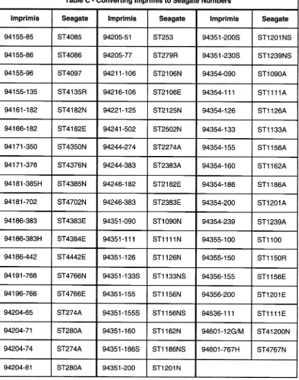
CDC, Imprimis or Seagate? 71
Miniscribe or Maxtor Colorado 71
Hard Drive Parameters 73
Alps 73
Aura 74
Atasi 75
BASF 75
Brand Technology 76
Bull 77
C.Itoh 77
Cardiff 77
CDC 78
Century Data 86
CMI 88
CMS Enhancements 89
Cogito 89
Conner 90
Core International 94
Corporate Systems Center 96
Data Tech Memories 99
Disctec 99
Disctron l 00
DMA 100 DTC 100 Ecol.2 101 Elcoh 101 Emulex 101 Epson 102 Espert 102 Fuji 102 Fujitsu 103 Hewlett-Packard 105 Hitachi 107 IBM 109 Iomega 110 IMI 111 JCT 111 Kalok 112 Kyocera 112 Lanstor 113 Lapine 113 Maxtor 114 MaxtorColorado 118 Megadrive 119 Memorex 119 Micropolis 120 Microscience 124 Miniscribe 128 Mitsubishi 131 MMI 132 NCR 132 NEC 133 NEI 134
Newbury Data 135
NPL 136
Okidata 136
Olivetti 136
Orca Technology 137
Otari 137
Pacific Magtron 137
Panasonic 138 Prairietek 138 Priam 139 Procom 141 PrI 142 Quantum 143 Ricoh 147 RMS 147
Rodime, Inc 148
Samsung 152
Seagate 152
Shugart 163
Siemens 164
Storage Dimensions 165
Syquest 166
Tandon 167
Tandy 168
Teac 169
Texas Instruments 169
Tokico 169 Toshiba 170 Tulin 172 Vertex 172 WesternDigital 173 Xebex 175 Ye-Data 176 Zentec 176 Controller Information...•...•...•.•...•••.••...•••.•..177
Adaptec Controllers 177
CCAT Controllers 178
Conner Peripherals Controllers 178
CSC Controllers 179
DTC Controllers 181
DTK Controllers (Data Enterprises) 184
Everex Controllers 184
Future Domain Controllers 185
Longshine Controllers 185
NCL Controllers 185
Seagate Controllers 186
SMS/OMTI Controllers 187
Storage Dimensions Controllers 188
Ultrastor Controllers 189
Wangtec Controllers 190
Western Digital Controllers 190
Connector Pinouts...•...••....•...•..•197
IDE Interface Pinout. 197
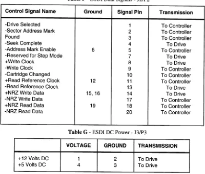
ESDIPinouts 197
IBM I/O Channel Pinout. 198
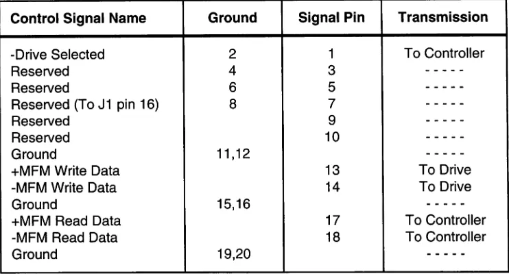
ST-506 Pinout 199
SCSI Pinout 200
SA-400 Pinout 20 1
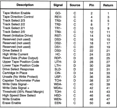
QIC-36 Pinout 202
Drive Jumpers...•...203
Atasi 3085 203
CDC Wren III Series 203
CSC Wren III Series (SCSIJumpers) 204
CDC Wren III Series (ESDI&SCSI) 205
CDC WrenVSeries 206
Conner IDE Drives 206
ConnerCPF 1060 207
Conner 2000 Series 207
Conner 3000 series/3044 208
Conner 30060 208
Conner 30064 209
Conner30104H 209
Conner30174E 210
Conner30200 210
Conner 30204 211
Conner30254 211
Conner 3040 212
Conner31370 212
Conner 3200X 213
Conner3184 213 Conner3360/3540 214 ConnerCFA340A 214 Conner344 215 ConnerCF340A 215 Conner5500 216
Fujitsu 2244,2245,2246 217
Fujitsu 226X Series 217
HitachiDK514C 219
HitachiDK515 225
Hitachi DK516 230
Maxtor LXT-100 231
Maxtor LXT-200A 231
MaxtorMXT-1240 232
Maxtor25128Aand2585A 233
Maxtor XT 1000/2000 Series 234
Maxtor 4000E Series 234
Maxtor Panther SCSI 236
Maxtor XT-4000S 237
Maxtor XT-8000S 238
Maxtor XT-8000SH 239
Maxtor LXT-SCSI 240
Maxtor XT 8000E Series 240
Micropolis 132X Series 241
Micropolis 135XSeries 242
Micropolis 137XSeries 242
Micropolis 155X Series 243
Micropolis 157XSeries 243
Miniseribe9380EDrives 244
Miniscribe 9380S Drives 245
Priam514,519 246
Priam 617, 628, 638 246
Priam 717, 728, 738 247
QuantumGo-DriveATJumpers 248
QuantumPRODRIVE Series 248
Seagate 5.25" MFMlRLLDrives 249
Seagate3.5"MFMlRLLDrives 250
Seagate SCSI Drives 250
esc
Benchmark Tests..••..••...•.•....••...••...•253About The Benchmarks 253
SCSI DRIVES 253
IDE DRIVES 254
SCSI Controllers 254
Floppy Drives•...•..•.•.•..•...•...•...257
Optical Disk Drive Technology 263
CD-ROM drives 263
WORM Drives 263
Erasable Optical Drives 263
Optical Drive Specitications 265
Optical Drive List 265
Tape Drives..•...•...•...•..•...•...•...273
Tape Drive Interfaces 273
iv
Floppy Tape 273
Pertee 273
QIC-02 273
QIC-36 273
SCSI 273
Data Compression and Honest Capacity 273
Choosing a Tape Drive 273
Tape Drive Performance Comparison 274
Colorado Jumbo "250MB" 274
Caliper CP-150B 274
lVC 4MM SCSI DAT 274
PerSci 9 Track 6250BPI reel-reel. 274
Extended Length Tapes 274
Manufacturers Phone List 277
Bulletin Board Services 281
Directory...•...•...•..•...••...•...••.••.•.••..••.••..•.•..283
Software.•...•..•....••.•...••.•..••••••.•.••.••..•••.••291
Disclaimer 291
Copyright Notice 291
System Notes..•....••.•...•...•293
Glossary...•...•....•..••.••295
The History
01
Disk Drives
The magnetic recording technology used in today' sdisk drives can be traced back to around 500 B.C. when the mineral magnetite was discovered. Magnetite is the naturally occuring magnetic material which was first used in compasses. Alchemists in the first century B.C. discovered the first magnetic compasses when they no-ticed that loadstones hung from a string always pointed the same way.
Several hundred years later, the connection be-tween electricity and magnetism was discovered. Early scientists noticed a compass needle was deflected when it was put near a wire carrying electric current. It was in this era that magnetic technology was pioneered by experimental geniuses like Danish physicist Hans Chris-tian Oersted and English scientist Michael Faraday who discovered the principles of electromagnetic induction.
The first practical magnetic recording device was the Telegraphone patented in 1898 by Danish telephone engineer and inventor Vlademar Poulsen. The Telegraphone was a crude audio recorder using a stretched magnetized wire. The Telegraphone attracted consider-able curiosity when it was first exhibited at the Exposi-tion Universelle in Paris in 1900. The few words that the Austrian emperor Franz Josef spoke into it at that exhibi-tion are believed to be the earliest surviving magnetic recording.
As World War I approached, the German war effort assumed leadership in magnetic recording technology. The German firm AEG was the first to use plastic strips (tape) for magnetic recording.The Germans put mag-netic recording to its first military application on subma-rines. Secret communications were recorded on crude reel to reel tape recorders at slow speeds. The tapes were then played back and retransmitted at high speeds to prevent Allied interception. The receiving station used another tape recorder to reconstruct the messages. By World War II the Germans had perfected the recording technology and manufactured high quality reel-to-reel tape recorders called Magnetophons. These tape record-ers were nearly identical to today's high quality audio tape recorders.
In 1945 an American Signal Corps soldier, John T. Mullin, sent two ofthese captured machines home to San Francisco. The analysis of these units by American engineers at Ampex Corporation lead to the development ofthe Ampex Model 200 in 1948. The Model 200 was the first magnetic recorder to be manufactured in volume and used commercially. American Broadcasting Corpora-tion had provided some of the financing for the Ampex recorder project, and was the first to use them in broad-casting the Bing Crosby Show in 1948. This same tech-nology is used in today's high resolution audio and
©CSC 1994
Figure1-Magnetophon Recorder
Corporate Systems Center (408) 734-3475
digital tape drives.
Reel to reel tape recorders and Hollerith punch cards were the main storage devices used in early com-puters. Paper Holerith cards and paper tapes were used to perform initial program loading when early computers were first powered up. Paper tapes were popularized by the Teletype Corporation who added paper tape readers and punches to many of their Teletype terminals. Paper tape remained popular for over 20 years, lasting until the early 1970's. It took the convenience and erasability of
floppy disks to eliminate paper tapes.
In 1952, IBM, realizing the need for a random access method of data retrieval with faster access than magnetic tapes, sent Reynold B. Johnson to San Jose, California to head up a magnetic recording research team. Johnson was convinced that a disk based system was the way to go, but other engineers advised him to abandon the project. Following his intuition, Johnson designed the first commercially successful digital disk drive. In 1956, IBM announced the Model 350 RAMAC
Figure2 -The Baloney Slicer!
(Random Access Method of Accounting and Control). It was a quantum leap in disk technology for its time. The RAMAC stored 5 megabytes of data on fifty 24-inch disks, spinning at 1200 RPM, and had an access time of 600 milliseconds, the resulting data transfer rate was .10 Mbits per second. Compare that to the 15 to 50Mbits per second data rates typical today! The popular name for
thi~hugestack of disks at IBM was the "baloney slicer". In 1955, realizing that magnetic recording density was severely limited by the number of linear stripes (tracks) on the tape, two brilliant engineers, Charles Ginsburg and Ray Dolby at Ampex Corporation devel-oped the helical scan recording system. Their ingenious scanning system uses a tiny spinning magnetic head with tape wrapped around it in a spiral. This design packed recording tracks much more tightly onto the tape than was previously possible. The helical scan recording technique provides an extremely high recording density with a single small head. Helical scan recording is now used in every video recorder (VCR), Digital Audio Tape drives (DATs), and all high capacity tape backup drives. I have read with respect several documents authored by Ginsburg and Dolby at Ampex. These engineers deserve more credit for their brilliant invention of the mecha-nisms and recording techniques copied in every modem VCR.
In 1961, IBM pushed disk data storage ahead by announcing the 1301 Disk Storage unit which used aerodynamically shaped recording heads that "flew" above the surfaces of the spinning disks, and enabling roughly 10 times as much information to be packed in each square inch of disk surface. This head design would eventually become the "Winchester disk drive".
The next year, IBM announced the 1311 Disk Pack unit which helped speed the end of the punched card era by providing removable and interchangeable"disk packs" containing six disks protected by a transparent plastic "cake cover." Each disk pack could store roughly as much data as 25,000 punched cards. Magnetic disks were finally becoming a practical storage medium for computers.
In 1964, my parents made the mistake of conceiv-ing Martin Bodo. Little did they know how much trouble I would eventually cause them. My early fascination with computers would ultimately place CSC at the forefront of magnetic data storage technology.
In 1967, IBM assigned David L. Noble to head a research team to develop a convenient storage medium
©
esc
1994with which to store and ship microcode. In 1969 several engineers left the project to join Memorex. Memorex soon became an industry leader in magnetic media tech-nologies, disk drive manufacturing, and magnetic media production.
In 1970, IBM announced the 3330 Disk Storage Facility which was the first disk storage product to use an electrical feedback system called a "track-following servo" to control a "voice coil" motor that could quickly position recording heads at desired positions over the disk. This combination provided better response time, higher track density, and more reliable operation than was previously attainable. Twenty years ahead of its time, this closed loop track following servo technology would eventually be used in every large capacity disk drive.
In 1971, the first "diskette" was produced by IBM as an ICPL (Initial Control Program Load) device. It was called the Minnow and was an 8-inch read-only model that stored 81,664 bytes. It caused paper tapes to become obsolete almost overnight.
While IBM and others were developing disk tech-nology at home in America, Japanese companies like Sony and Japan Victor Corporation (JVC) were making rapid advances in consumer VCR technology. By the early 1980's, the Japanese had a lead in helical scan tape drive manufacturing technology which the US could never overcome.
In 1973, the first read-write floppy disk, the Igar (IBM 33FD), started shipping to customers, storing an incredible (for its time) 242,944 bytes. The original code
Figure3 -IBM 33FD Floppy Drive
Corporate Systems Center (408) 734-3475
name of the read-write disk was Figaro, but the initial f and final0 were removed as a symbolic removal of "fat" and "overhead". Memorex was the first company after IBM to produce floppy disk products and soon became a strong competitor in this field.
Also in 1973, IBM announced the 3340 Disk Stor-age Unit, which featured an ultra light-weight recording head that could "land" on and "take off" from a lubricated disk while it was still spinning. This eliminated the need for a mechanism to raise the heads off the disk surface before stopping, substantially reducing the cost ofmanu-facturing. The 3340 also contained two spindles, each with a storage capacity of 30 million characters. Refer-ring to this arrangement as a "30-30," engineers were reminded of the famous rifle and called their creation a "Winchester" file, a term that came to be used throughout the industry to identify this "floating head" design.
In 1975, IBM announced the 3350 Direct Access Storage Device, and marked an extension of Winchester technology and a return from the removable disk pack to fixed disks, permitting higher recording densities and lower cost per bit for on-line storage. The 3350 could store data at a density of more than 3 million bits per square inch, an increase of more than 1500 times the density of the RAMAC. By this time, competitors were catching up. Several companies, including Shugart, Magnetic Peripherals Incorporated, and PerSci were about to introduce competitive floppy disk drives.
In 1976, the success of the 33FD floppy disk led to the development of the 43FD using a dual-head drive, which could store 568,320 bytes. This was followed a year later by the double-density, double-sided, 53FD using MFM encoding and a capacity of 1,212,416 bytes. By 1977, nineteen companies were manufacturing floppy disk drives in the United States and MFM had become the encoding method of choice.
In 1979 Seagate Technology was founded and was the first company to mass produce an affordable hard disk drive (the 5 Megabyte ST506). Seagate has become the largest independent manufacturer of hard drives, having shipped over 35 million units to date.
I was a runny-nosed high school sophomore in 1979. While IBM was inventing thin-film recording heads, I was content with my first 5.25" 160K floppy drive. I was hooked, but I didn't know it.
The data storage industry exploded in the early 1980's with the help of brilliant engineers who had business sense. Allen Shugart made the floppy disk the standard for data interchange and floppy drive sales
4 Hard Drive Bible
soared. By 1982, hard disk drive sales had exploded and form factors were shrinking from 14" disks to 8" disks. The 5.25" form factor made popular by Seagate's ST506 was now an industry standard.
When I graduated from college in 1986, I made a living by modifying Alan Shugart's Model 712, 5.25" 10 megabyte hard drives so they would hold 20MB. I was starting to understand the equation for success in the hard drive industry. It was simple: Provide the Most Megs in the Smallest Size for the Least Bucks. I saw an oppor-tunity for a company which would initially provide repair services for disk drives. CSC was born in 1986.
In 1989, IBM announced the 3390 Direct Access Storage Device, which could store as much as 21.5 billion characters in each storage unit -- the same capac-ity as its predecessor, the 3380 Model K, but at an increased density that required only one-third the floor space. Gosh, it weighed only 800 pounds.
As sales of Apple Computer's Macintosh line of personal computers began to grow, the industry was introduced to the idea of using the Small Computer Systems Interface (SCSI) interface as a standard port for desktop PC peripherals. SCSI at this point was basically a glorified 8 bit parallel port. But SCSI would eventually grow into one of the most popular standards for both low performance PC and higher performance workstation disk drives! Like the IBM-PC, SCSI caught on like crazy because it was hardware with software standards in-cluded.
In 1990, Conner Peripherals in parthership with Compaq computers had created and made popular both the IDE interface and the 3.5" disk drive form factor. An enormous volume market for IDE drives grew in the next few years as IBM compatible desktop systems grew in popularity.
Early Conner IDE Drive
By 1990, there was not one American company left producing helical scan tape recording mechanisms. The Japanese conquest in consumer electronics was about to payoff. Soon, all helical scan digital tape recording mechanisms for computer technology would come from Asia. In addition the American loss of consumer audio manufacturing technology would cost US companies dearly. All digital CD-ROM disk drives based on this technology would now come from Japan and the orient. In 1991, we designed our first caching disk control-lers at CSC. These cards would eventually sell by the thousands, as the size of CSC continued to double yearly. In 1991, IBM boasted another first in drive technol-ogy, the MR head. IBM's 9340 drive became the first IBM disk to use magneto-resistive recording-head tech-nology, and IBM could now boast of bit densities of
>1OOMbits per square inch.
In 1992, improvements in mechanical alignment and media had boosted the capacity of standard diskettes to 2.88MB and "floptical" diskettes to 20MB. Maxtor Corporation announced the "Magic" MXT series of disk 3.5" disk drives with capacities over 1GB and access times under8ms. 5.25" disk drives were available in 1992 with over 3GB of formatted capacity.
It's 1994 now, as we write the update to the Hard Drive Bible. It's hard to predict the future, but I'll be glad to share a few thoughts on the data storage industry.
My friends in the floppy industry tell me that Hoptical drives will soon be shipping with 80 MB capacity in a standard 3.5" form factor. I'm not sure what industry standards will develop, but other than "floptical" drives, I don't see much future for the floppy disk indus-try. Read the chapter on ROM for more insight. CD-ROM and recordable CD-CD-ROM drives are now about to revolutionize software distribution.
The hard disk industry, on the other hand, is moving faster than ever. Volumes are huge and a few manufac-turing companies staying profitable despite intense com-petition. Technology is advancing faster than ever. My friends and I used to talk about "mini-mono" disk heads. Then it was "micro-sliders" and even "nano-sliders". Today we had a nerd's lunch and talked about "pico-sliders" that fly at 4 millionths of an inch above the disk. As far as I'm concerned, that should be called "contact recording"!
Will hard drive sales continue to grow? To be honest, there are some potential challengers for hard drives. Optical, and Hash technologies are improving.
©
esc
1994You can bet our friends at Intel think Hash will kill hard drives. But our friends in Japan working on optical disk drives feel that optical drives will win out in the long run. My opinion is unchanged. I've heard people tell me that something better will replace hard drives for the last ten years. Every time there's a technical advance in Hash or optical drive, there's a corresponding advance in disk drive technology. Hard drives are here to stay. As
magnetic, optical, and semiconductor technologies ad-vance together, hard drives continue to offer more stor-age for less money, with a better access time. Each technology has it's distinct advantages, but the magnetic recording technology used in hard drives is simple, mature and easy to manufacture. Hard drives will remain practical for at least several more years.
In 1993, only one major disk drive manufacturer was able to maintain profitability. I take my hat off to Alan Shugart, CEO of Seagate Technologies for that accomplishment. Seagate has a broad line of products from 8" drives to PCMCIA FLASH memory. They're quick on their feet and poised for the future.
But the majority of disk drive manufacturers con-tinue to loose money! This is an omen of the largest potential problem facing the data storage industry: price competition. Severe price competition is forcing many companies to abandon research efforts and concentrate on high volume, low-tech products. Only the lean, high tech companies will survive the competition.
Some feel that magnetic recording technology has now begun to give way to optical technologies. I agree that optical technology has now become affordable and reliable enough to replace magnetic drives in some applications. In the past few years, optical recording techniques pioneered by the Japanese in consumer prod-ucts have developed to the point where optical drives are manufactured at reasonable costs. Many companies like Hitachi, Sony, Ricoh, and MaxOptix do a brisk business selling fast, reliable, low cost optical drives. I feel the compelling advantage behind optical media is remov-ability. Cartridge hard drives and hard drives with re-movable HDA's are not as large or convenient as optical media. The market for erasable optical drives will con-tinue to grow.
Corporate Systems Center (408) 734-3475
Interlace Standards
With every new developing technology comes the problem of standardization. The data storage industry has been influenced by standards from manufacturers and various groups including:
ANSI
American National Standards Institute 11 West 42nd Street, 13th Floor New York, New York 10036-8002 (212)642-4900 (212)398-0023 Fax
NAB
National Association of Broadcasters 1771 North Street, N.W.
Washington, DC 20036-2891
(202)429-5300 (202)429-5343 Fax
IBM
First in standards for drives and computers IBM Personal Computer Division
Route 100
Somers, NY 10589 (800) 772-2227
IRCC
International Radio Consultive Committee
IRIG
Interrange Instrumentation Group
Shugart Associates
Pioneer in floppy disk drives Shugart Associates
9292 Geronimo, Building #103 Irvine, CA 92718
(714)770-1100
Seagate Technology
Pioneer in hard disk drives Seagate Technology 920 Disc Drive
Scotts Valley, CA 95067
(408)438-6550 (408)438-6356 Fax
©CSC 1994
Some of the popular standards that have evolved are listed below:
With the emergence of IBM compatible PCs as a hardware standard, drive manufacturers have recently started to integrate much of the IBM controller hardware onto their disk drives. These drives are called "Intelligent Drive Electronics" or "Integrated Drive Electronics" (IDE) drives. This interface is often referred to as the "ATA" or "IBM Task File" compatible interface. Drives with an 8-bit IDE interface are often called "XT Inter-face" drives, and drives with a 16-bit interface are often called "AT Interface" drives. By imbedding an AT con-troller card into the drive, a significant manufacturing cost savings occurs. Many parts (including line drivers and even a microprocessor) may be eliminated.
Early "XT Interface" drives use a BIOS ROM on the paddleboard and cannot be interchanged with "AT Interface" drives. An XT Interface controller and drive may be used in an AT class computer if the CMOS is set to "no drive installed".
Conner Peripherals and Compaq Computer were among the first companies to ship IDE drives in volume. Since then, acceptance ofthe IDE interface based on their original design has grown.
Since the imbedded controller on an IDE drive is optimized to run efficiently with the drive it is attached to, IDE interface drives often operate with improved performance over their comparable MFM or RLL coun-terparts. Some sacrifices were made in MFM/RLL con-troller and drive design to ensure compatibility with a large range of drives. Imbedded controllers are usually faster due to optimization.
It is clear that IDE drives have rapidly replaced the original MFM and RLL drives used in early IBM-AT compatible applications. Since most new disk drives use zoned recording techniques to increase drive capacity, all of these drives must use imbedded controllers. The only practical interface alternative for imbedded controllers on small disks are IDE or SCSI.
One disadvantage ofthe IDE interface is the 528MB
Corporate Systems Center (408) 734-3475
limitiation. Although the most popular IDE drives sold today are less than 528MB, disk sizes continue to grow. A modification to the IDE interface software standard is now proposed so that drives over 528MB can be sup-ported. See the Enhanced IDE chapter for more informa-tion on how the IDE interface will be improved in the future.
Another minor problem with the IDE interface is hardware incompatibility. Some IDE drives may be incompatible with each other or with some paddle boards, mostly due to different buffering or decoding. See the pinout in the Connector Pinouts section for more information on IDE drives.
81-506/81-412 Interface
Seagate Technology is the world's largest manufac-turer of hard drives. Their first ST506 five megabyte full-height 5.25" disk drive was one of the first hard drives manufactured in volume. This drive used a 5 Mbitl second MFM encoded interface. The standard interface copied from this drive was used in all "ST-506 compat-ible" MFM and RLL drives.
MFM and RLL Encoding
Modified Frequency Modulation (MFM) encoding was first patented by Ampex Corporation in 1963. MFM encoding is often called "double density" and is used to code data on floppy and hard drives. MFM is an attractive coding scheme mainly because it is simple to encode and decode. MFM is now the standard coding technique for floppy disk drives and some small capacity hard disk drives.
Run Length Limited (RLL) encoding is a group coding technique which provides an increase in data density over MFM encoding. In RLL encoding, streams of data are grouped together and each group of data produces a recording pattern which depends on the bits which came before it. RLL encoding eliminates high frequency flux transitions and permits an increased data density within a fixed recording bandwidth.
The most common RLL coding (RLL 2,7) provides a 50% improvement in recording density over MFM coding. For example, a drive which stores 100MB ofdata at 5Mbitlsec MFM data rate can be made to store 150MB of data using RLL encoding. The data transfer rate increases to 7.5Mbitlsec using RLL 2,7, while the record-ing bandwidth stays at 5 Mhz.
8 Hard Drive Bible
Other RLL codings can provide even higher re-cording densities. RLL 3,9 (commonly called ARRL) provides a 100% improvement in recording density. Longer codes can provide even greater increases. Be-cause RLL coding does not require an increased read! write channel bandwidth when compared to MFM en-coding, RLL is now a popular coding technique used to increase capacity in many hard disk drives. Most modern ESDI, ST506-RLL and SCSI drives use RLL encoding. For a more detailed description ofhow RLL data is coded and decoded, see the next chapter.
Since RLL encoding provides higher data density in the same recording bandwidth, the data capture win-dow is reduced. To accurately reproduce data in this smaller capture window, RLL encoding requires an im-proved data separator, an accurate read channel, and better PLL circuitry. The rotational speed of the disk drive must also remain more constant. Simply put, there is less margin for error using RLL encoding. Because of this, only drives specifically designed for ST506 RLL encoding should be used with RLL controllers. Connect-ing an ST506 RLL controller to a drive designed for MFM applications can result in a loss of data integrity. Before RLL'ing a drive, check with the manufacturer to insure that the drive is RLL certified. Be very careful when using ARRL controllers.
E8Dlinterface
The Enhanced Small Device Interface (ESDI) is basically an improved, high speed ST-506 interface. This interface was pioneered by Maxtor. The combination of a 34-pin control cable and a 20-pin data cable from the ST-506 interface are retained, but the ESDI interface features improved actuator commands and data transfer rates.
The ESDI interface uses a data separator located on the disk drive itself. Older ST-506 designs used a data separator on the controller card instead. Moving the data separator to the drive improves compatibility and makes the ESDI interface independent of data rate. Providing the maximum data transfer rate of the controller is not exceeded, any speed ESDI drive can be connected to any controller. ESDI drives are available with rates up to 28 Mbits/sec.
The ESDI interface offers less command overhead than the SCSI interface. However, ESDI is not particu-larly well suited to zoned recording, and is really only useful for fixed disks. ESDI remains a useful, fast
interface for hard disks, but SCSI has won out in popularity. The attraction of being able to daisy chain peripherals like CD-ROM and SCSI tape drives has ultimately driven the industry away from ESDI and toward SCSI.
SCSI Interface
The Small Computer Systems Interface (SCSI) first became popular as the interface used for Apple Macintosh peripherals. Actually, SCSI has been used for quite some time in workstation applications and is rapidly gaining popularity in the PC marketplace. SCSI offers the ability to daisy chain up to seven devices (hard, optical, tape, etc.) to a single controller with a single cable.
SCSI is basically a high-speed bidirectional 8-bit parallel interface that has been standardized in terms of both hardware and software by ANSI. The SCSI bus allows addition of up to 7 devices using a daisy-chained cable. Unfortunately, though most manufacturers ofSCSI peripherals adhere to the basic ANSI hardware specifica-tions, the level of SCSI software compatibility varies from manufacturer to manufacturer. A new ANSI stan-dard, SCSI-II has been announced in an attempt to standardize the SCSI software interface. The ANSI SCSI-II specification adds features like disconnect/reconnect, and messaging while maintaining downward compat-ibility with SCSI-I devices. A recent copy of the SCSI specification may be obtained from ANSI or the CSC BBS.
Good termination and shielding allow a "single wide" SCSI bus to operate at speeds in excess of 10MB/ sec. Since most existing SCSI peripherals only sustain data rates of around 2-3MB/sec, the SCSI interface has the data bandwidth to handle higher speed drives in the future.
The new SCSI-II standards for Wide SCSI and Fast SCSI offer a wider bus and sustained transfer rates up to 40MB/sec. These new versions of SCSI offer more than adequate throughput for any storage device that might appear in the near future.
The SCSI interface offers the flexibility and room for future expansion, but brings with it all the problems of a developing technology.
WIDE SCSI
Currently, the terms "wide SCSI" and "double wide SCSI" are used to refer to a SCSI interface with a 16 bit
©CSC1994
wide data path. This interface uses a 68 pin connector, and the electrical handshaking and data transfer system is identical to the more common 8 bit "single wide" SCSI bus. The ANSI SCSI specification provides a method for negotiating with peripherals to determine if they offer "wide SCSI" capabilities. Theoretically, the wide SCSI bus is downward compatible with standard "single wide" SCSI devices.
FAST SCSI
"FAST SCSI" refers to SCSI handshaking system which reduces hardware overhead during data transfers. Peripherals which support this feature will transfer data at higher burst rates if they are connected to a controller which also supports FAST SCSI. If either the peripheral or the controller does not support FAST SCSI, the burst data transfer rate is unaffected.
SMD Interface
The Storage Module Device (SMD) interface is the most popular interface for the 8" drives used in main-frame, minicomputer, and workstation applications. Variations include an improved data transfer rate (HSMD). SMD drives are gradually being replaced by SCSI in most applications. Bridge controllers are now available to adapt newer ESDI drives to the SMD interface.
IPllnterface
The Intelligent Peripheral Interface (IPI) is a main-frame disk drive interface standard used mainly on 8" and 14" drives. It is popular in IBM and Sun workstation and minicomputer applications. Many drives are available with dual IPI ports.
QIC-02 Interface
This QIC-02 interface is a software standard for tape drives. Most PC based 1/4" tape controllers use a QIC-02 command set.
QIC-40 Interface
This interface uses an standard floppy controller to store data on minicartridge data tapes. Although they are relatively slow, these drives are popular in PC applica-tions due to their low cost. Drives are now available with
Corporate Systems Center (408) 734-3475
up to 250MB (500MB compressed) capacities and data transfer rates up to 1Mbit/sec.
OIC-36 Interface
This 50-pin tape drive interface standard was pio-neered by companies like Wangtec and Archive. The pinout is listed in the Pinout Section.
SA-400 Interface
As with Seagate and the ST-506 Interface, the SA-400 interface is named after the originator of the first mass produced floppy disk drive. Shugart Associates manufactured the SA-400 in 1978 and the SA-400 was the first disk drive to gain wide acceptance. The interface used a simple 34-pin cable with the 17 odd numbered pins connected to ground for noise reduction and shield-ing.
This 34-pin interface was modified to create the ST-506 hard disk drive interface discussed earlier in this section. The pinout of the interface used in modern floppy disk drives is shown in the Pinout Section. Al-though additional functions have been added since the original SA-400 drive (mainly DISK_CHANGE, SPEED_SELECT, and DRIVE_READY), this pinout is still affectionately referred to as the SA-400 interface.
Future Standards
Currently the most popular disk drive interface for small capacity hard drives is the IDE (or AT) standard. In the immediate future, the PC market will continue to be dominated by IDE drives.
The most popular interface for high performance, large capacity drives in now SCSI. In the future, as SCSI software standards evolve and the costs of SCSI drives and controllers come down, much of the IDE market will be displaced by SCSI.
In workstations and high-end PC applications, it seems clear that SCSI is the interface of the future. For example, all of the popular optical and DAT drives use the SCSI interface. We look forward to the time when small computer peripheral interfacing is simplified as manufacturers all begin to conform to the new SCSI-III and future SCSI-IV standards.
Basic Drive Operation
All disk drives perform three basic functions. They spin, seek, and transfer data. The disks inside a hard drive are mounted and rotated by a motor normally located in the center of the disks called the spindle motor. The read/ write heads are held and moved in a head carriage which also usually holds the preamplifier electronics. Disks and heads are stacked vertically on the spindle motor, and the head stack assembly is positioned on-track by a servo system. Raw read data flows from the preamplifier and is encoded and decoded by the drive electronics. The heads read and write this "encoded" data to the disks (media). Data encoding and decoding circuitry is designed to pack as much information as possible into the smallest area. Read/write circuits move the encoded data to and from the magnetic recording heads. When writing, the heads convert the electric currents from read/write circuits into highly concentrated magnetic fields. These magnetic fields are stored in miniature magnetic groups called "domains" on the surface of the disk. When reading, the magnetic domains stored on the media are converted into electric currents as the heads pass by a second time, this time operating in reverse. The heads convert the chang-ing magnetic fields from the disk into electric currents as the read data is recovered. The sections below describe the operation and purpose of the basic components of a disk drive: the spindle motor, the servo system, heads and media, and the data encoding circuitry.
Spindle Motors
The motor used to rotate the disks in a drive is called a spindle motor. Disk drives use many different types of spindle motors. The type used determines the spin-up time of the disk and torque as well as the heat dissipation inside the drive. A motor with a high start-up torque is necessary since the extremely flat heads and disks used in modem drives tend to stick together when power is removed and the heads land on the disk. At the same time, the spindle motor must operate efficiently with a mini-mum power consumption. Heat dissipated inside a disk drive causes the mechanical parts in the actuator and disk assembly to expand. Because modern drives require extremely precise mechanical alignment, it is essential
©CSC 1994
that thermal expansion caused by spindle motor power dissipation be kept to a minimum. Some early drive designs were plagued with stiction or heat problems caused by inadequate spindle motors. Newer designs have resolved these problems by providing spindle mo-tors with higher start-up torques and lower power sumption. All modem drives use microprocessor con-trolled spindle motor drive circuitry with pulse width modulation to minimize power consumption once the drive reaches operating speed.
Figure 4- Spindle motor used in high-capacity Maxtor drives.
In high capacity disk drives the quality of the bearings used in the spindle motor assembly is becoming increasingly important. As the concentric tracks in a drive are pushed closer and closer together in an effort to gain higher storage capacities, spindle bearing "mnout" becomes a consideration. The smallest amount of wobble in a modern disk assembly can throw a head assembly slightly off track, resulting in reduced data integrity. Drive manufacturers have gone to great lengths to find affordable spindle motor bearings which offer the lowest amount of mnout while still providing long life.
Early hard drives spun at 60 revolutions per second (3600 RPM) because synchronous motors were used which locked to the 60 Hz AC line frequency. Some newer designs now offer "fast spin" rates of up to 7000
Corporate Systems Center (408) 734-3475
RPM. At these higher spin speeds, improved spindle motor bearing quality and balancing is essential. Faster responding servo systems are also required to track data at higher spindle speeds.
Head Carriage
The mechanical engineer asked to design a modem head carriage is faced with a difficult task: Design a perfectly balanced mechanism to hold the heads firmly and rigidly using existing bearing and actuator technol-ogy. And management wants it for free! The head car-riage must have the lowest moving mass possible, en-abling it to be moved hundreds of time a second.
Figure 5Head carriage with linear actuator
The head carriage pictured above uses a linear actuator. The advantage of this type of actuator is that the heads always stay parallel to the recording track. The disadvantages are more complexity and moving parts (higher cost) and higher mass than a rotary actuator.
Head carriage with rotary actuator
The head carriage above is typical of a modem
12 Hard Drive Bible
rotary actuator. This actuator system has become standard in modem hard disk drives for two main reasons. Rotary actuators are cheap and reliable. Typically only two ball bearings are needed at the top and bottom of the actuator.
Media and Heads
The ultimate limiting factors in the push for higher and higher data densities in today's drives are the heads and media. Hard disk media was originally manufactured by spin depositing iron oxide (rust) particles on machined aluminum disks. Modern disks
Figure 6- 5.25" Plated media
are made of annealed aluminum which is sputtered and plated with magnetic coatings, then coated with rugged lubricated coatings. Disk media is classified by the amount of magnetic field in Oersteds (Oe) required to produce enough magnetic dipole reversals in the disk coating to be detected by a magnetic head. Earlier media was easily magnetized using fields of 600 Oe or less. Newer high density media requires fields of 1800 Oe or more to achieve sufficient mag-netic penetration.
Head technologies have also evolved over the years. As head gaps become smaller, the size of the magnetic coils used must shrink accordingly. New heads must handle higher write currents and be more sensitive when reading. Head gap sizes are constantly shrinking and because of this, the drive industry is moving toward the thin film and magneto-resistive heads of the future and away from monolithic heads of
yesterday. Head flying heights are now just a few mil-lionths of an inch to enable efficient magnetic coupling with miniscule gap widths.
Stepper Motor Servo Systems
Stepper motors are rotary actuators that rapidly move in small discrete steps (usually .8 to 4 degrees per step). Stepper motors provide a simple, reliable position-ing system that is easy to use and inexpensive to manu-facture. The stepper motor shaft is usually connected to a small metal band that converts the rotary shaft motion into a linear or rotary motion ofthe head carriage. Stepper motors are ideal positioners for floppy drives and low capacity hard drives due to their low cost.
A low cost stepper motor servo system has two major disadvantages. The mass of the rotor in a stepper motor is generally high. Using stepper motors as actua-tors in disk drives produces low access times because the heavy rotor must be moved along with the head carriage.
Stepper Motor Servo
The number of concentric tracks recorded per inch on a disk drive is referred to as the "track density". The second disadvantage in a stepper motor servo system is limitations on track density. High track densities are difficult to achieve with stepper motor servo systems because most stepper motors move only in large discrete steps. The electronics required to "fine tune" the position of a stepper motor servo system are expensive to manu-facture. It is easier to adjust the position of a voice coil and keep the heads on track than it is to fine tune a stepper motor.
The future of stepper motors remains in low cost open-loop servo systems, like floppy disk drives. They
©CSC 1994
have become yesterday's technology, and there's no reason to use them in hard disk drives today.
Voice Coil Servo Systems
It's hard to imagine a mechanism that can move to any position over an inch in less than11100thof a second and come to a complete stop within 0.0001" of its target. Modem voice coil actuators are capable of doing this over 1,000,000,000 times. The voice coil servo system is the key component in all newer high performance disk drives. A voice coil actuator is simply a coil of copper wire attached to the head carriage. This coil is surrounded by high energy permanent magnets which are attached to the HDA casting. To move the head carriage and "seek" to a track, the control electronics apply a current to the voice coil. The current applied induces a magnetic field in the coil which attracts or repels the stationary perma-nent magnets. The amount of torque induced to move the head carriage is directly proportional to the amount of current applied to the voice coil.
Many drives use an ASIC control chip in the voice coil servo system which contains aDIA converter. The output of the D/A converter usually drives a MOSFET power amplifier which provides the current required by the voice coil. The circuitry which moves the head from track to track is simple compared to the circuitry which decodes the servo information recorded on the drive. In order to control the voice coil, the servo electronics must know precisely where the head is positioned on the drive. The positioning information fed back to the electronics to control the voice coil positioner is called "servo feed-back". Several different servo schemes are used to pro-vide position feedback information to the drive electron-ics and "close" the servo loop.
Some large capacity drives use a "dedicated" voice coil servo feedback system. If you see a drive in the drive
Voice Coil Servo
Corporate Systems Center (408) 734-3475
table with an odd number of read/write heads, it probably uses a dedicated servo system. In a dedicated system, the entire surface of one disk is reserved for use by the servo system. Position information is recorded on the reserved (dedicated) disk so that the drive electronics can deter-mine the exact position and velocity of the head carriage. Assuming that the head carriage holds the entire head stack rigidly together, the position ofthe read/write heads will track along with the dedicated servo head. A dedi-cated servo system offers fast positioning and is simple to design. One of the only disadvantages to this system is that since only one head is used for servo, a dedicated servo system is unable to compensate for thermal warpage of the head stack assembly.
A more popular voice coil servo feedback system is called "embedded" servo. An embedded servo system works in a manner similar to the dedicated system except for the physical location of the servo position informa-tion. An embedded system interleaves servo and data information by placing servo positioning bursts between the data recorded on the disk. Embedded servo systems have advantages and disadvantages over dedicated servo systems. Advantages of an embedded system include the ability to accurately position each individual head by sensing the position information directly under that head. A dedicated servo system positions all of the heads together. Disadvantages of an embedded servo system are increased servo electronics complexity (which trans-lates to higher cost), and the requirement for seek and settling delays when switching between heads.
Many new drives employ a "hybrid" servo system which combines both a dedicated servo for fast, coarse positioning, and an embedded servo to finely position the head on track. Hybrid servo systems offer the best access and positioning of any system, but their cost is also the highest. One disadvantage this system shares with dedi-cated servo systems is that an entire surface is used for servo. This dedicated surface could have been used to store more data..
Keeping it Clean
When a drive is running, Winchester heads "fly" or "float" on a cushion of air. There is virtually no wear on the disk surface when the drive is running and the heads are stationary. Almost all the wear on a drive occurs when the drive is turned off and the heads "land" and touch the disk.
14 Hard Drive Bible
Figure7 -Drive Filter and Latch Components
All modern voice coil servo drives use an electronic or mechanical mechanism to move the heads away from the data area of the disk to a "landing zone" when power is removed. Better drives also use a mechanical latch mechanism to park and lock the heads in the landing zone.
As the media wears in a drive, microscopic par-ticles flake off from the disk surface. A quality hard drive designed for long life contains a circulating air system which catches these particles in a filter.
Most disk drives have filtered vents which permit outside air to enter and exit the HDA. These vents help if a pressure differential develops between the HDA and the ambient air. Some newer drive designs (notably Conner and Maxtor drives) have eliminated the outside air filter.
Data Encoding and Decoding
Data encoding is the technique used to convert a stream of binary data into a varying current which drives a magnetic head. The varying current which drives the head produces magnetic flux reversals in the head. These flux reversals orient the molecular magnetic dipole mo-ments of the media. The media is thus "magnetized" in a pattern which stores the data. The magnetic head has a maximum frequency limitation which determines how close the magnetic flux reversals can be placed on the disk while still maintaining acceptable reliability. There is also a minimum frequency limitation imposed by the drive electronics.
data recording rate translates to higher capacity per track and higher data transfer speeds. The magnetic recording bandwidth of a drive is limited by several factors includ-ing head and media design and positioninclud-ing accuracy.
The goal in designing data encoding and decoding circuitry thus becomes placing the maximum amount of data bits within a fixed recording bandwidth while main-taining acceptable reliability.
Disk drive data encoder circuitry removes the need to place clock information on the track by combining the data bits to be recorded with as few clock signals as possible. The decoder circuitry regenerates the clock from the recorded signal and synchronizes the clock to the decoded data. The encoder and decoder circuitry in a drive are usually combined into a chip called and "ENDEC".
Encoding and Decoding Codes
The following encoding and decoding codes are commonly used in disk drives:
NRZ (Non-Return to Zero)
This code was originally used in telecommunica-tions and its encoding and decoding are simple to under-stand. Instead of discrete pulses for each data bit, the signal rises or falls only when a one (1) bit in the incoming data stream is followed by a zero (0) bit or when a zero (0) bit is followed by a one (1) bit.
This coding technique has a serious flaw because certain data patterns can be generated which will result in a fixed logic state output (i.e. the output of the encoder will be static, stuck at zero or one). The "worst-case" condition can violate the minimum recording bandwidth of the drive electronics. In practice, this would rarely happen, but it's a serious strike against NRZ coding.
PE (Phase Encoded)
This coding is used in credit cards and instrument recorders. It is also simple to understand. The direction of a flux reversal in the middle of each cell indicates whether the encoded bit is either a zero or a one. This effectively shifts the phase of the output signal each time there is an NRZ type transition between zeros and ones.
FM (Frequency Modulation)
©
csc
1994This coding technique was used in the earlier floppy drives (including 8" drives). These older drives were called single density "SD" drives. The FM method of encoding is basically equivalent to the PE method. FM coding is no longer widely used in disk drives.
MFM (Modified Frequency Modulation)
With available heads and media, MFM is by far the easiest coding technique to implement MFM encoding is used in all modem floppy drives and many small capacity hard drives. MFM doubles the data capacity of FM encoding (MFM floppy drives are called Double Den-sity). MFM works by eliminating the clock pulses in FM encoding and replacing them with data bits. Clock pulses are still used, but they are written only when a one (1) data bit is not present in both the preceding and the current data cell ( Fig. 8)
To decode MFM data, a data separator must gener-ate a clock signal based on several flux transitions. In
BIT
POSITION 1 2 3 4 5 6 7 8 9 10
NRZ MESSAGE DATA CLOCK MFM CODE
Figure8 -MFM Encoding
order to maintain a low error rate, the speed of data flowing into the encoder must remain steady, and the decoder must lock onto this stream. In practice, the rotational speed of hard and floppy drives is easily controlled within the tolerances required for reliable MFM recording.
RLL (Run Length Limited Encoding)
This encoding scheme was first used in 14" drives from IBM, CDC, and DEC. It is now used in almost all high capacity 3.5" and 5.25" hard drives. Common RLL coding techniques are RLL 1,7 and RLL 2,7. 1,7 and 2,7 refer to the maximum number of consecutive zeros in the code. RLL 2,7 offers a500/0improvement in data transfer rate and data recording density as compared with MFM within the same fixed recording bandwidth.
Corporate Systems Center (408) 734·3475
The easiest way to understand RLL encoding is by examining Figure 9. Bits are encoded by following the tree, starting at the root. When you reach the end of a branch, the stream of bits at that branch correspond to the encoded data to be written to the drive.
RLL encoding has two main disadvantages. The first is that RLL requires significantly more complex encoding and decoding circuitry than MFM. This has
Figure9 -RLL2,1Encoding Tree
been overcome in part by single ENDEC chips from companies like SSI and National Semiconductor. The second disadvantage with RLL encoding is that a small defect can produce a long stream of data errors. To combat this, drive manufacturers are improving the design of read/write heads and media and lowering the flying height of these heads to improve signal to noise ratios. Longer, improved error correcting codes are also used with RLL encoded drives.
Spindle motors are now driven by crystal con-trolled microprocessors to improve rotational speed ac-curacy. The quality of the heads, media, and spindle control circuits used to manufacture today's hard disk drives are more than adequate for reliable RLL encoding
Future Codes
Many other coding and encoding techniques have been developed which offer higher data rates and record-ing densities than RLL within the same fixed recordrecord-ing bandwidth. All of these codes are more susceptible to timing jitter and large error bursts than RLL coding. At present, nearly all ESDI, SCSI, and IDE drives use RLL coding. We expect that RLL will continue to be the most commonly used coding in magnetic mass storage de-vices for the next few years. The recent advent ofPRML techniques to improve read channel performance will take some time to implement.
CD-ROM
CD-ROM
CompactDisk ReadOnlyMemory is the future of software distribution. Programs which were once shipped on dozens of floppy disks can now be reproduced inex-pensively on a single CD-ROM disk.
With over 600 Megabytes of capacity, CD-ROM technology provides a medium for full motion multime-dia games, movies, and educational software. This new technology will replace the floppy disk for information distribution in the near future, and may eventually re-place some magnetic tape technologies, such as video tape. Well established standards insure media inter-change between different CD-ROM drives, platforms, and operating systems.
At the time of this writing, the cost of mass produc-ing a CD-ROM in Hong Kong had dropped to around 50 cents per disk. On a per megabyte basis, CD-ROM is the most inexpensive way to distribute data.
CD MEDIA
CD-ROM disks are built on a transparent polycar-bonate plastic substrate. This substrate is coated with a thin aluminum layer. Recordable, write once CD media is identical to mass produced disks, except that the aluminum layer is replaced with gold. CD's store infor-mation using microscopic pits in the metal layer which are detected by a minute laser beam. Each pit is approximately 5 by 3 micrometers in size, and there are over a billion pits per disk. Since these pits are much smaller than dust particles, CD's must be manufactured in a clean room environment. To provide an immunity from smaller dust particles and unavoidable scratches, the optical recording layer is placed away from the surface of the plastic disk.
To mass produce CD-RaM's. CD masters are first made using a photo lithography process. These masters are then used to press thousands of disks. Smaller quantities of disks can also be produced on a desktop using a CD-R drive. A CD-R drive uses write-once media and is similar in operation to a WORM drive.
CD-ROM DRIVE OPERATION
Unlike hard disk drives, CD-RaM's are not
seg-©CSC 1994
mented into multiple tracks of data. Technically, a CD-ROM disk has only one track! The CD-ROM uses a single track of data over three miles long which is wound 50,000 times in a spiral, similar to an LP record. On a CD, data is recorded from the inside of the spiral out-wards. A single speed CD-ROM drive spins the disk at varying speeds, starting at 550RPM and working down to about 220RPM. It takes about 75 minutes to read the entire disk at this "single" speed.
Data is encoded using an "EFM" modulation scheme which isn't the ideal way to pack data on an optical disk, but it was chosen to keep the complexity and cost of the drives down. As the disk spins, a tiny low power laser is focused through a lens onto the surface ofthe disk. The reflected light from this laser is detected using a photo diode, and the EFM encoded data is detected and sent to the drive electronics. Because a scratch or dust particle can cover thousands of bits of data, a special error correcting system called CIRC (for Cross Interleaved Reed Soloman Code) is used to correct any errors de-tected by the drive electronics.
Two closed loop servo systems are used in CD-ROM drives. The first system moves the small focusing lens located above the laser to focus it on the disk. The second system moves the entire laser, lens, and photo diode assembly to place it correctly on the spiral.
CD ROM STANDARDS
ISO 9660
ISO-9660 is the current International Standards Organization technical specification which defines the physical format of CD-ROM data. The major contribu-tors to this specification were DEC, Phillips and Sony. This specification evolved from the "High Sierra" for-mat, and is now used in almost all mass produced CD-ROM disks to insure compatibility in the wide range of available drives and systems. The ISO 9660 specifica-tion defines file and directory formats, interchange lev-els, and recording formats. A copy of the ISO 9660 specification can be ordered from ANSI by calling (212) 642-4900.
MODE1
Two "modes" or formats are used to record data on