© 2019, IRJET | Impact Factor value: 7.211 | ISO 9001:2008 Certified Journal
| Page 2290
Effect of Soil- Structure Interaction on Response of Building Frame wit
Piled-raft Foundation
R. Mahadev Swamy
1and Dr. S.A. Rasal
21
Associate Professor, Department of Civil Engineering, Shivajirao S. Jondhale College of Engineering and
Technology, Asangaon
2
Assistant Professor, Department of Civil Engineering, Datta Meghe College of Engineering, Navi Mumbai-400708.
India.
---****---
Abstract:
The effect of soil structure interaction on response of the three storeyed (G+2) building frame supported on piled-raft foundation is reported in this paper. The three storeyed frame comprises of two bays and columns of the frames are supported by a piled-raft. The pile is assumed to be embedded in the cohesive soil mass. For the purpose of the analysis, simplified idealizations made in the theory of finite elements. The slab of the frame is idealized as two dimensional plate elements, beams and columns of the superstructure frame and pile of the sub-structure are idealized as the one dimensional bem-column elements. The soil mass is idealized byequivalent springs. The effect of different raft thicknesses with uniform pile diameter is evaluated on the
response of superstructure through a parametric study. The response of the superstructure considered includes the displacement of the frame.
Keywords: Pile-raft, soil modulus, raft thickness, displacement
1.
Introduction
The type of foundation and its design is based on the magnitude of the loads on it and the type of founding strata which supports it. If the founding stratum is within a reasonable depth, a shallow foundation in the form of raft is adequate. However, if the material is weak, the loads need to be transferred down to capable strata by means of deeper basements or piles. This is true, especially in case of multistoried building frames resting on weak sub soil strata where heavy structural loads acting on the frames have to be transmitted safely below to the firm strata.
The analysis of piled-raft foundation is very challenging because the load in the piled-raft structures is transferred to the soil not only by the interaction between the soil and the piles but also by the interaction between foundation structure and superstructure. In this interaction, deformations in the soils are the key factor which will affect forces and deformation in foundation and superstructure
In the past few decades, there has been an increasing recognition that the use of pile groups in conjunction with the raft can lead to considerable economy without compromising the safety and performance of the foundation. Such a foundation makes use of both the raft and the piles, and is referred to here as a pile-enhanced raft or a piled raft. The piled-raft concept has also proven to be an economical way to improve the serviceability of foundation performance by reducing settlements to acceptable levels. Although the piled-raft concept has been most notably applied to new construction involving high-rise buildings it is also potentially useful for remedial works and moderate height structures.
Methods that have been used for the analysis range from simplified calculations to numerical methods such as the boundary element method (Butterfield and Banerjee [1], Brown and Wiesner [2], Kuwabara [3], Mendonca and De Paiva [4]) and the finite element method (Hooper [5], Ottaviani [6], Chow [7], Liu and Novak [8], Katzenbach and Reul [9], Prakoso and Kulhawy [10], Reul and Randolph [11]). In early years because of the limited availability of computer memory and processing speed, the use of numerical methods was confined to simple problems. In last three decades due to rapid development in computer technologies, numerical methods such as full three dimensional finite element methods are often used to solve the complex problems.
© 2019, IRJET | Impact Factor value: 7.211 | ISO 9001:2008 Certified Journal
| Page 2291
2.
Brief Review of Literature
In recent years, a variety of approaches for analyzing the piled- raft foundation system as mentioned in the preceding section have been developed over the years. All these approaches vary in the degree of sophistication of the formulations amount and the type of input parameters required, assumptions made; and in the applicability to realistic pile-soil-raft situations. Some of the significant studies are briefed approach wise in the subsequent paragraphs.
The approximation approach as presented by Chen et. al. [12] treated the raft as a thin plate, the piles as springs and the
soil as an elastic continuum; and further, the interaction effects between the piles were ignored. Randolph [13] presented a method to compute the interaction between a single pile and a circular raft. Clancy and Randolph [14] employed a hybrid method in which analytical solution was combined with the finite elements. The raft was modeled by two-dimensional thin plate finite elements, the piles were modeled by one-dimensional rod finite elements and the soil response was calculated by using an analytical solution. Poulos [15] employed a finite difference method for the raft with the consideration of the interaction effects between the piles and raft. Kitiyodom and Matsumoto [16] developed a simplified method of numerical analysis using a hybrid model in which the flexible raft is modelled as thin plates and the piles as elastic beams and the soil is treated as springs.
The finite element method is one of the powerful tools for the analysis of the complex problems of piled raft. In order to reduce the computational efforts, the problems are sometimes simplified to an axi-symmetric problem or a plane- strain
problem. Some of the noteworthy contributions using this method include those by Poulos et al. [17], and Sawant et al.
[18]. Some of the researchers analyzed the circular piled rafts while few of them, reported the performance of piled raft foundation for a muti-storeyed building. Some of the analyses were carried out in the context of non-linear behaviour of soil; few of them even used finite elements in conjunction with infinite elements. While some investigations considered sandy soil, few of them considered the cohesive sub-soil. Even, a study considered layered soil. Some studies were carried out using complete three-dimensional finite element analysis; few studies were carried out in the context of simplified finite element models.
The boundary element method is a powerful tool that can be applied in engineering applications as only the boundary has to be discretized which reduces the amount of computer memory and the time to solve the problem as compared to that in finite element or finite difference method. This method provides a direct and accurate solution for the analysis. Moreover, it is fast and requires a moderate amount of computer storage space. The method has been used by many researchers
(Brown and Wiesner [19], Kuwabara [20], Baziar et al. [21]) in the solution of the problem of piled raft embedded in
different types of soil. Different idealizations were made for modelling different components of the foundation in question.
Based on the afore-mentioned review of literature, the analysis of a piled raft is presented using a software programme Build-Frame developed using FORTRAN 90. After assessing the accuracy of the programme in the context of simple problems of structural engineering and soil- structure interaction and further, implementing it on the published work, the said program is used in the present study. The present study aims at comparing the response of the piled-raft foundations with non-interactive, linear interactive and nonlinear-interactive analysis. The response of the frame included the displacement at each storey level of the frame along with the maximum positive and maximum negative bending moments in the individual beams and columns. A parametric study is carried out to examine the effect piled-raft on static nonlinear response with 0.5m thickness of the raft and 0.4 m pile diameter. The pile is assumed to be linear elastic throughout the analysis and soil is modeled using von Mises yield criteria.
3.
Problem Description
A 3-D three storeyed building frame resting on piled-raft foundation is considered for the study. The frame, 3 m high is 10
m 10 m in plan with each bay being, 5m 5m. The slab, 200 mm thick, is provided at top as well as at the floor level. The
slab at the top of the first, second and third storey is supported over 300 mm wide and 400 mm deep beams. The beams
are resting on columns of size 300 mm 300 mm. While dead load is considered according to the unit weight of the
materials of which the structural components of frame are made up of, for the purpose of the parametric study presented here. The properties of the material for pile and pile cap are given in Table 1.
Table 1. Pile-raft and soil properties for parametric study
Soil properties
© 2019, IRJET | Impact Factor value: 7.211 | ISO 9001:2008 Certified Journal
| Page 2292
Poisson's ratio,
s 0.4
Density, γs 18 kN/m3
Yield stress, σy 100 kPa
Interface element
Normal stiffness, Kn 1.0 × 10⁶ kN/m3
Tangential stiffness, Ks 1000 kN/m3
Piled-raft properties Modulus of Elasticity, E
p 25 GPa
Poisson's ratio,
p 0.2
Density, γp 25 kN/m3
(a) Building frame with fixed base-half symmetry (b) Building frame with piled-raft
Fig.1 Building frame considered in the present study
The schematic of the building frame with fixed base-half symmetry and piled-raft is shown in Fig. 1 (a) and (b). While dead load is considered according to unit weight of materials of which the structural components of frame are made up for the parametric study presented here, a
lateral load of 1000 kN is assumed to act at joints of the frame. The analysis carried out in the context of linear behavior of soil is extended further to account for the non-linearity of the soil using von Mises yield criterion.
3.1
Effect of Pile Diameter on Storey Displacement
© 2019, IRJET | Impact Factor value: 7.211 | ISO 9001:2008 Certified Journal
| Page 2293
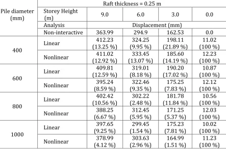
Table 2
Effect of pile diameter on storey displacement for raft thickness 0.25 m.
Pile diameter
(mm)
Raft thickness = 0.25 m
Storey Height
(m)
9.0
6.0
3.0
0.0
Analysis
Displacement (mm)
Non-interactive
363.99
294.9
162.53
0.0
400
Linear
(13.25 %)
412.23
(9.95 %)
324.25
(21.89 %)
198.11
(100 %)
11.02
Nonlinear
(12.92 %)
411.02
(13.07 %)
333.45
(14.19 %)
185.60
(100 %)
12.23
600
Linear
(12.59 %)
409.81
(8.18 %)
319.01
(17.02 %)
190.20
(100 %)
10.87
Nonlinear
(8.59 %)
395.24
(9.35 %)
322.46
(7.83 %)
175.25
(100 %)
12.12
800
Linear
402.42
(10.56 %)
(2.48 %)
302.22
(11.84 %)
181.78
(100 %)
10.56
Nonlinear
(6.67 %)
388.25
(5.95 %)
312.45
(5.37 %)
171.25
(100 %)
12.03
1000
Linear
397.65
(9.25 %)
299.45
(1.54 %)
175.23
(7.81 %)
10.02
(100 %)
Nonlinear
(4.12 %)
378.99
(2.96 %)
303.63
(1.51 %)
164.99
(100 %)
11.23
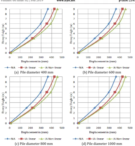
The general trend observed for all the pile diameters considered in this investigation is that horizontal displacement at each storey level increases due to the effect of soil structure interaction (SSI). It is seen that the displacement at top of each storey is on higher side corresponding to four different pile diameters (400, 600, 800 and 1000 mm) considered in the present investigation when compared with the values of top displacement obtained in non-interactive analysis.
The reduction in the displacement is attributed to the improved passive resistance of soil with higher pile diameter. The general trend observed for all the pile diameters considered in the investigation in respect of all the pile diameters is that horizontal displacement is more when the diameter is less and thereafter, decreases with higher value of pile diameter considered in present study.
© 2019, IRJET | Impact Factor value: 7.211 | ISO 9001:2008 Certified Journal
| Page 2294
(a) Pile diameter 400 mm
(b) Pile diameter 600 mm
(c) Pile diameter 800 mm
(d) Pile diameter 1000 mm
Fig 2:
Effect of pile diameter on storey displacement for raft thickness 0.25 m.
4.
Conclusions
From the parametric study presented in this paper, following significant conclusions can be drawn:
The effect of soil- structure interaction on each storey displacement of the frame is quite significant. Displacement is
less for the conventional analysis and increases when nonlinearity of soil is considered.
With increase in pile diameter, storey displacement decreases in respect of all pile dimeters considered in the study. A
displacement for minimum raft thickness and higher value of soil modulus is on higher side.
It is seen that the displacement at top of each storey is on higher side corresponding to four different pile diameters
considered in the present investigation when compared with the values of top displacement obtained in non-interactive analysis
[image:5.595.65.528.58.557.2]© 2019, IRJET | Impact Factor value: 7.211 | ISO 9001:2008 Certified Journal
| Page 2295
5.
References
1. Butterfield, R. and Banerjee, P. K. (1971), “The problem of pile group - pile cap interaction”, Geotechnique, 21(2),
135-142
2. Brown, P. T. and Wiesner, T. J. (1975), “The behaviour of uniformly loaded piled strip footings”, Soils and
Foundations, 15 (4), 13-21
3. Kuwabara, F. (1989), “An elastic analysis for piled raft foundations in a homogeneous soil”, Soils and Foundations,
29(1), 82-92
4. Mendonca, A. V. and De Paiva, J. B. (2003), “A Boundary element method for the static analysis of raft foundations
on piles”, Engg. Analysis with Boundary Elements, 24, 237-247
5. Hooper, J. A. (1973), “Observations on the behaviour of a piled-raft foundation on London Clay”, Proc. Int, Jl. Civ.
Eng., 55 (2), 855-877
6. Ottaviani, M. (1975), “Three-dimensional finite element analysis of vertically loaded pile groups”, Geotechnique,
25 (2), 159-174
7. Chow, Y. K. (1987), “Axial and lateral response of pile groups embedded in non-homogeneous soil”, Int. Jl. Num.
Analyt. Meth. Geomech., (11) 6, 621-638
8. Liu, W, and Novak, M. (1991), “Soil-pile-cap static interaction analysis by finite and infinite elements”, Canadian
Geotech. Jl., 28, 771-783
9. Katzenbach, R., Arslan, U. and Moormann, C. (2000), “Piled raft foundation projects in Germany”, Design
Applications of Raft Foundation, Thomas Telford, 323-391
10. Prakoso, W. A. and Kulhawy, F. H. (2001), “Contribution to piled raft foundation design”, Jl. Geotech. and Geoenv.
Engg., ASCE, 127(1), 17-24
11. Reul, O. and Randolph, M. F. (2003), “Piled rafts in over consolidated clay: Comparison of in- situ measurements
and numerical analyses”, Geotechnique, 53(3), 301-315
12. Chen, K. S., Karasudhi, P. and Lee, S. L. (1974), “Force at a point in the interior of layered elastic half-space”, Int. Jl.
Solids Struct., 10(11), 1179-1199
13. Randolph, M. F. (1983), “Design of piled raft foundations”, Proc. Int. Symposium on Recent Developments in
Laboratory and Field Tests and Analysis of Geotechnical Problems, Bangkok, 525—537
14. Clancy, P. and Randolph, M. F. (1993), “An approximate analysis procedure for piled raft foundations”, Int. Jl. Num.
and Analyt. Meth. in Geomech., 17(12), 849–869
15. Poulos H.G. (1994), “An approximate numerical analysis of piled raft interaction” Int. Jl. Num. and Analyt. Meth. in
Geomech., 18 (2), 73–92
16. Kitiyodom, P. and Matsumoto, T. (2003), “A simplified analysis method for piled raft foundations in
non-homogeneous Soils”, Int. Jl. Num. Analyt. Meth. in Geomech., 27(2), 88-109
17. Poulos, H.G., Badelow, F., Small, J.C., Moyes, P. (2006), “Economic foundation design for tall buildings”. Proc. 10th
Int. Conf. on Piling and Deep Foundations, Amsterdam, 200-209
18. Sawant,V. A., Ladhane, K. and Pawar, S. (2012), “Parametric study of piled raft for three load-patterns”, Coupled
System Mech.: An Int. Jl., 1(2), 115-131
19. Brown, P. T. and Wiesner, T. J. (1975), “The behaviour of uniformly loaded piled strip footings”, Soils and
Foundations, 15 (4), 13-21
20. Kuwabara, F. (1989), “An elastic analysis for piled raft foundations in a homogeneous soil”, Soils and Foundations,
29(1), 82-92
21. Baziar, M. H., Ghorbani, A., Katzenbach, R. (2009), “Small-scale model test and three-dimensional analysis of piled