Abstract—In the present investigation, the corrosion
behaviour of dissimilar A319 and A356 cast Al alloys plates joined by friction stir welding (FSW) was evaluated. The effects of tool rotational and welding speeds as well as post-weld heat treatment (PWHT) on corrosion behaviour were investigated. Plates of A319 and A356 were friction stir welded (FSWed) using three different tool rotational speeds (typically, 1120, 1400 and 1800 rpm) and two welding speeds (typically, 80 and 112 mm/min). The PWHT was carried out using a solution heat treatment temperature of 540 oC for 12 hours followed by ageing at 155 °C for 6 hours. Corrosion behaviour of welds was investigated by immersion in sodium chloride (NaCl) and hydrogen peroxide (H2O2) solution for 6
hours. The results showed that both as-welded (AW) and PWHTed welds showed better corrosion resistance than both A319 and A356 base alloys. The corrosion resistance of the welded zones was found to be reduced by increasing the tool rotational speed and/or reduction of the welding speed.
Index Terms—Friction stir welding, Aluminium cast alloys, Corrosion behaviour.
I. INTRODUCTION
The corrosion behaviour of FSWed aluminium alloys has been described in recent years [1-6]. Generally, it has been found that the weld zones are more susceptible to corrosion than the parent metal. Friction stir (FS) welds of aluminium alloys such as 2219, 2195, 2024, 7075 and 6013 did not exhibit enhanced corrosion of the weld zones [1,7,8]. FS welds of aluminium alloys exhibit intergranular corrosion mainly located along the nugget‟s heat-affected zone (HAZ) and enhanced by the coarsening of the grain boundary
Manuscript received February 20, 2010
Ahmed S. Hassan is an M. Sc. Student at Mechanical Engineering Department, Benha University, Shoubra faculty of Engineering, Cairo, Egypt. (Phone: 002-010-8266688; fax: 002-02-22023336; e-mail: [email protected]).
Tamer S. Mahmoud is an Associate Professor at Mechanical Engineering Department, Shoubra Faculty of Engineering, Benha University, Cairo, Egypt. Currently at King Khaled University (KKU), Faculty of Engineering, Abha, Kingdom of Saudi Arabia, (Phone: 00966-054-8688576; fax: 00966-62418184;e-mail:Tsmer@ kku.edu.sa or [email protected]). Fouad H. Mahmoud is an Associate Professor at Mechanical Engineering Department, Shoubra Faculty of Engineering, Benha University, Cairo, Egypt. (Phone:002-010-0036141; fax: 002-02-22023336; e-mail: [email protected]).
Tarek A. Khalifa is a Professor at Mechanical Engineering Department, Shoubra Faculty of Engineering, Benha University, Cairo, Egypt. (Phone: 002-010-1343329; fax:002-02-22023336; e-mail: tkhalifa50@ yahoo.com).
precipitates. Coarse precipitates and wide precipitate-free zones promoted by the thermal excursion during the welding are correlated with the intergranular corrosion.
The effect of FSW parameters on corrosion behaviour of friction stir welded joints was reported by many workers [5,9]. The effect of processing parameters such as rotation speed and traverse speed on corrosion behaviour of friction stir processed high strength precipitation hardenable AA2219-T87 alloy was investigated by Surekha et al. [9]. The results indicate that rotation speed has a major influence in determining the rate of corrosion, which is attributed to the breaking down and dissolution of the intermetallic particles. Jariyaboon et al. [5] studied the effect of welding parameters (rotation speed and travel speed) on the corrosion behaviour of friction stir welds in the high strength aluminium alloy AA2024–T351. It was found that rotation speed plays a major role in controlling the location of corrosion attack. Localized intergranular attack was observed in the nugget region for low rotation speed welds, whereas for higher rotation speed welds, attack occurred predominantly in the HAZ.
Many investigators studied the corrosion resistance of Al alloys weld joints made by using FSW and other conventional fusion welding techniques such as Metal Inert Gas (MIG) and Tungsten Inert Gas (TIG) [10,11]. For instance, a comparison of the corrosion resistance of AA6060T5 and AA6082T6 joints made by Friction Stir Welding (FSW) and Metal Inert Gas (MIG), respectively, is reported by Stefano and Chiara [11]. Tests were conducted by putting the welded and polished samples in an acid salt solution. Corrosion resistance was detected via morphological analysis of the surface. The attack was localized (pitting), an index referred to the pit density was used for the comparison. The results indicated that joints welded using FSW are more resistant to corrosion than those welded using MIG. An experimental investigation has been carried out, by Squillace et al. [10], on microstructure and corrosion resistance of weld butt joints of AA 2024-T3 welded using FSW and TIG techniques. Polarization curve tests and electrochemical impedance spectroscopy showed a nobler behaviour of weld bead with respect to parent alloy. In FSW joints, however, the differences between the nugget, thermo-mechanically affected zones (TMAZ) and heat affected zones (HAZ) were not so evident as in TIG joints; what is more, inside FSW weld bead, the retreating zone showed a behaviour nobler than the advancing one.
Corrosion Behaviour of Dissimilar A319 and
A356 Cast Aluminum Alloys Joined By Friction
Stir Welding (FSW)
It has been found that most of the work carried out in the field of corrosion resistance of FSW is focusing on wrought Al alloys [1-11], especially, high strength alloys such as 7XXX and 2XXX series. Corrosion resistance of cast aluminium alloys such as A319 and A356 FSW joints has not been reported. However, the mechanical and microstructural characteristics of FSWed joints of such alloys have been examined extensively by many workers [12-15]. The aim of the present work is to study the corrosion behaviour of dissimilar A319 and A356 cast aluminium alloys plates joined by FSW. The effect of tool rotational and welding speeds as well as PWHT on corrosion resistance of the welded joints is studied.
II. EXPERIMENTAL PROCEDURE
In the current investigation, dissimilar joints of cast aluminium alloys A356 and A319 were produced using FSW. Plates of such alloys were received in the form of ingots and machined into thick plates having the dimensions of [50 mm (width) × 250 mm (length) × 10 mm (thickness)]. The chemical composition of the A356 aluminium alloy (by weight percent) was 6.72% Si, 0.25% Fe, 0.11% Cu, 0.27% Mg, 0.04% Zn, 0.043% Ti and balance Al. While the chemical composition of the A319 aluminium alloy (by weight percent) was 6.48% Si, 0.25% Fe, 3% Cu, 0.002% Mg, 0.013% Zn, 0.003% Mn and balance Al.
The FSW operation carried out in the present work is shown in Fig.1a which indicates the tool rotational and welding directions. It is clear that the tool was rotating at a counter clockwise direction. On the basis of preliminary studies the A356 Al alloy was placed at the retreating side and the A319 Al alloy on the advancing side of the rotating tool. A steel tool made from H13 steel was used as a welding tool. The chemical composition of the tool material was 0.39% C, 0.40% Mn, 5.2% Cr, 0.95% V, 1.4% Mo, 1.10% Si and balance Fe. The tool has a simple cylindrical shape shown in Fig 1b. The rotating pin travels along the butt line between the two parent alloys. The welding processes were conducted using a vertical CNC milling machine at three different tool rotation speeds, typically; 1120, 1400 and 1800 rpm and two different welding speeds of 80 and 112 mm/min. In all experiments, the tool angle was fixed at 2° and the friction pressure was held constant by keeping the tool‟s shoulder penetration depth inside the work piece constant at 2 mm.
Post weld heat treatment (PWHT) of welds was carried out using a solution heat treatment temperature of 540 oC for 12 hours followed by ageing at 155 oC for 6 hours. Test pieces from as-welded (AW) and PWHTed joints were cut along the transverse direction in order to analyze their microstructural, mechanical and corrosion properties. Microstructural characteristics of friction stir (FS) welded plates were investigated using an optical metallurgical microscope. After grinding and polishing, micro-etching was carried out using a chemical solution (0.5 ml HF 40% + 100 ml of H2O) for 5–60 s at ambient temperature. The chemical composition of the elements and second phases in the stir zone was analyzed by a scanning electron microscope (SEM) equipped with an
energy dispersive X-ray spectroscopy (EDX) analysis system. Additionally, second phases in the stir zone were identified by the X-ray diffraction (XRD) method. The sizes of the primary Si particulates were measured using standard quantitative methods via a metallurgical image analyzer. Vickers hardness at the centre of the processed zone was measured for both AW and PWHTed samples on the cross-section perpendicular to the welding direction using a load of 1 kg. The hardness measurements were conducted on specimens prepared for metallographic examination.
Fig.1. FSW operation (a) and tool dimensions (b).
Immersion corrosion tests were performed on etched AW and heat treated samples according to ASTM standard G110 [16]. This standard practice evaluates the intergranular corrosion resistance of heat treatable aluminium alloys by immersion in sodium chloride (NaCl) + hydrogen peroxide solution (H2O2). The samples were
immersed in a solution of 57 g/l (0.98 M) NaCl and 10 ml/l H2O2 (0.09 M) for 6 h. Prior to immersion in the test solution, the samples were cleaned with acetone to remove organic materials such as oils and other residuals. Specimens were then immersed for 1 min in etching cleaner ( 945 ml of reagent water + 50 ml of nitric acid (70%) + 5 ml of hydrofluoric acid (48%) ) followed by washing in reagent water. After that, the specimens were immersed in concentrated nitric acid (70%) for 1 min followed by washing in reagent water and dry air. After immersion in the test solution, metallographic sections were examined using an optical microscope to determine the extent of intergranular corrosion.
III. RESULTS AND DISCUSSION
distribution of Si particles in base alloys was not homogeneous. The A356 Al alloy exhibited smaller α-Al grains size as compared with A319 Al alloy. Moreover, the A356 base Al alloy showed finer eutectic structure when compared with the A319 as shown in Fig. 2.
[image:3.595.304.548.155.293.2]Fig.2. Microstructures of base alloys: (a) A319, (b) A356
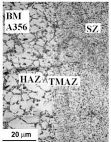
Fig.3. Microstructure of AW joint at the retreating side of welded zone showing the different SZ, HAZ, TMAZ and BM
regions using a tool rotational speed of 1400 rpm and a welding speed of 80 mm/min.
Fig. 3 shows the microstructure of the AW joint at the retreating side (A356 side) of the welded zone for samples FS welded at a tool rotational speed of 1400 rpm and a welding speed of 80 mm/min. Figure 3 shows the different regions observed in the vicinity of the weld centre line. It is clear that beside the base materials (BM), the microstructure of the FSW alloy shows three distinct zones, typically, (1) fine-grained dynamically recrystallized stirred zone (SZ), (2) thermo-mechanically affected zone (TMAZ), and (3) heat affected zone (HAZ). The TMAZ zone experiences both temperature and deformation during FSW and is characterized by a highly deformed structure. The HAZ is the zone that is believed to be unaffected by any mechanical effects but only the thermal effects caused by the frictional heat generated by the shoulder and tool pin rotation.
The microstructure of the SZ is very different from that of the BM. The SZ has a much more homogeneous microstructure as compared to the BM (see Fig. 3). The dendrite structure found in the BM disappeared and finer Si particles are dispersed over the whole weld zone. The material within the FSW zones experienced intense stirring and mixing which resulted in the breakup of the coarse acicular Si particles and the dendritic structure and gave a homogeneous distribution of the Si particles throughout the Al alloy matrix. It is important to mention that the SZ exhibited extra fine and equiaxed α-Al grains; however, it
was very difficult to identify the grain boundaries using the optical microscope. The TMAZ are formed besides the SZ in both the advancing side (AS) and the retreating side (RS) (only the retreating side is shown in Fig. 3). The microstructure of the TMAZ on the RS exhibits a sharp transition from the SZ to the BM. A wider zone of this deformed structure is observed on the AS which shows a more diffuse transient region.
Fig.4. Micrographs of the microstructure of the AW joints at the centre of welded zone produced at several tool rotational
and welding speeds.
Fig. 4 shows micrographs of the Si particulates at the centre of the SZ of the FSW joints welded at different tool rotational and welding speeds. As compared to the base metal shown in Fig. 3, FSW microstructures exhibit the breakup and/or redistribution of the primary Si particulates. In the base metals, the acicular Si particles are distributed at the boundaries of the primary α-Al phase and at the formed eutectic structure. It is clear from micrographs presented in Fig. 4 that for the SZ of the welded joints the Si particles are homogeneously dispersed and the acicular Si particles have disappeared. Fig. 5 shows the variation of size of Si particles with tool rotational speed for both welding speeds of 80 and 112 mm/min. The results revealed that, at a constant welding speed, the size of Si particles increases with increasing the tool rotational speed. The results revealed also that increasing the welding speed from 80 to 112 mm/min, at a constant tool rotational speed, reduced the average size of Si primary particulates. For example, at a tool rotational speed of 1400 rpm, increasing the welding speed from 80 to 112 mm/min reduces the average size of the primary Si particulates from 2.3 to 1.5 µm. According to the above results, it can be concluded that the average size of the Si particles increases with increasing the tool rotational speed and the reduction of welding speed. Increasing the tool rotational speed and/or reducing the welding speed raises the heat input during the FSW which affects the size of the Si particles. The size of the Si particles should increase with increasing heat input [12,14].
[image:3.595.112.225.250.394.2]speed. However, it is not significantly affected by the rotational speed. Kim et al. [14] showed also that the size of the Si particles in the retreating side is almost the same as that on the advancing side. Based on their results, they considered that the size of the Si particles should be affected by material temperature. They suggested that Si particles will be finer and more granular due to solid collisions at lower temperatures as a result of the more difficult plastic deformation. According to the above results, it is clear that the size of the Si particulates in the SZ is significantly influenced by both tool rotational and welding speeds. The combination between the tool rotational and welding speed is very important and plays an important role in determining the size of Si particulates.
Fig.5. Variation of the average size of Si particles at the centre of AW joints with the tool rotational speed at 80 and
112 mm/min welding speeds.
SEM micrographs of the irregular shaped regions at the welded zones are shown in Fig. 6 which shows a specimen welded at a tool rotational speed of 1400 rpm and a welding speed of 80 mm/min. The Al, Si, Cu and Mg distributions in these regions were analyzed using EDX. These results show that the mixture structure involves Al, Si, Cu and Mg. The material in weld zone has undergone the co-action of high temperature action and severe plastic deformation during FSW. In this case, the original coarse primary Al grains and large plate-like eutectic silicon in both base materials have been transformed to fine grains and small silicon particles in the SZ. Fig. 6a shows that there are two regions indicated by A and B. EDS maps indicate that regions “A” and “B” apparently have different chemical compositions, i.e. region „„A‟‟ has higher Cu (see Fig. 6d) and lower Si and Mg contents than region “B” (see Fig. 6c and 6e, respectively). The aforementioned results indicate that the irregular regions in the welded zones are a mixture structure of the two base alloys. Such a mixture is due to joining the two alloys either by mechanical bonding or chemical bonding or by both. Such results obtained in the current work were observed also by many workers for FSW of dissimilar alloys [17-19].
Hardness distributions on the transverse cross-section of AW and PWHTed joints FS welded at several tool rotational speeds are shown in Fig. 7. In the AW conditions, the hardness of the welded region is higher than that of both parent metals. The AW A319 Al alloy exhibited slightly higher hardness values as compared to the AW A356 Al alloy. Generally, PWHT increased the hardness of the A319 and A356 base metals such that the hardness of the welded region became lower than that of the parent metals. Any
precipitation hardening effects that may have occurred in the parent metals during PWHT was not noticed in the welded zone. Softening of the highly cold worked material near the weld centre line accompanied by annihilation of dislocations may have offset precipitation hardening effects.
Both AW A356 and A319 Al alloys exhibited wide scattering in hardness values. The A319 AW Al alloy exhibited hardness values varying from 70 to 90 VHN, while the AW A356 Al alloy exhibited hardness values varying from 60 to 78 VHN. The wide scattering in the hardness values of the A356 and A319 Al base alloys is attributed to the non uniform distribution of the Si particles inside the Al matrix since it is well known that the hardness of Al-Si alloys depends on the point measured by the hardness indenter [12,20]. Fig. 8 shows the variation of the hardness at the centre of the SZ with FSW parameters. In both AW and PWHTed conditions, the hardness at the centre of SZ was found to increase with raising the welding speed and/or reducing the tool rotational speed.
Fig.6. Qualitative EDX maps of Al (b), Si (c) Cu (d) and Mg (e) distribution in the irregular shaped region shown in (a) for AW joint at the retreating (A356) side. In each EDX map,
points with the higher concentration are white coloured. Specimen welded at a tool rotational speed of 1400 rpm and a
welding speed of 80 mm/min.
Figures 9 and 10 show optical photographs of cross sections perpendicular to the welding direction for the AW and PWHTed conditions respectively, after immersion in a solution containing sodium chloride (NaCl) + hydrogen peroxide (H2O2) for 6 hours. Examination of the photographs
revealed that, both AW A356 and A319 aluminium base alloys showed practically the same corrosion products on their surfaces. There is no noticeable corrosion behaviour difference between the two base materials. On the other hand, in the PWHTed samples, the corrosion products were concentrated heavily on the A356 side. Less corrosion products are observed on the A319 parent metal side.
at a welding speed of 80 mm/min, increasing the tool rotational speed from 1120 to 1400 rpm enhanced the formation of corrosion products inside the welded zone. White small particles formed inside the welded zone are found to increase by raising the tool rotational speed. It is observed also that, at a welding speed of 112 mm/min and at tool rotational speeds of 1400 and 1800 rpm, the entire welded zones are covered completely with corrosion products (see Fig. 9e and 9f). Regions showing dark black corrosion products are indicated in Fig. 9a and 9d by arrows. Regions 1 and 3 are in the SZ near the upper side while regions 2 and 4 are near the TMAZ. It is clear that both the upper regions of the SZ and adjacent TMAZ regions have corroded very severely and corrosion products are seen throughout the surface. However, in the upper SZ regions, corrosion is less severe than that occurring adjacent to TMAZ regions. The TMAZ adjacent to the nugget is where the metal is plastically deformed and also heated to a temperature, which is not sufficient to cause recrystallisation. The TMAZ exhibits equiaxed grains with sizes larger than that of the SZ. This increases the possibility of reducing the corrosion resistance of the TMAZ. Moreover, it may be suggested that the temperature reached within the TMAZ during FSW was insufficient to cause dissolution of the precipitates which resulted in an increase in corrosion severity.
Fig.7. Hardness distributions on the transverse cross-section of AW (a) and PWHTed (b) joints FS welded at several tool
rotational speeds.
Fig.8. Variation of hardness at the centre of welded zone with tool rotational speeds at different welding speeds.
Fig.9. Macrostructure of AW joints at several tool rotational and welding speeds.
For the PWHTed samples (see Fig. 10), corrosion appears to occur across the entire welded sections without a clear differentiation between the weld micro-zones. Corrosion was observed mainly at the A356 base metal side and continues to cover the entire welded zone. It seems that the AW zones exhibited lower corrosion products when compared with PWHTed zones. Moreover, at constant welding speed, increasing the tool rotational speed increases the amount of corrosion products on the surface of the PWHTed welded zone and on the corresponding A356 base metal surface.
Fig.10. Macrostructure of PWHTed joints at several tool rotational and welding speeds.
Micrographs of the A319 and A356 base metals after the immersion tests in NaCl/H2O2 solution are shown in Figs. 11
Continuous network of the intermetallics at the grain boundaries such that intergranular cracks can propagate. All the above three conditions are met for the base metals. Hence, the base metals corroded intergranularly. The A356 base metal may have become more volunerable to corrosion after PWHT due to formation of grain boundary precipitates to a greater extent as compared to A319.
Fig. 12 shows micrographs, at the center of the welded zone (stirred zone, SZ), for the as-welded conditions after the immersion tests in NaCl/H2O2 solution. It is observed from
[image:6.595.83.254.277.396.2]the micrographs that corrosion attack is less in FS welded samples compared to the base metals. The A319 and A356 base metals have corroded intergranularly whereas only a few pits were seen in the FS welded zones. In the SZ, the propagation of intergranular corrosion starts at pits. This indicates that it needs more time for intergranular corrosion to develop. Hence, the FS welded zones have better corrosion resistance compared to the base metals.
Fig.11. Micrographs of the typical localized corrosion after the immersion tests in a NaCl/H2O2 solution for 6 hours: (a)
AW BM A319 parent metal, (b) AW BM A356 parent metal, (c) PWHTed A319 parent metal and (d) PWHTed A356
[image:6.595.305.545.460.575.2]parent metal.
Fig.12. Microstructures of AW conditions at the centre of the welded zone produced at several tool rotational and welding
speeds
Examination of the figures revealed that the tool rotational and welding speeds have an influence on corrosion behaviour of FS welded regions. However, it seems that the tool rotational speed has a more significant influence on corrosion than the welding speed. Increasing the tool rotational speed, at 80 or 112 mm/min welding speeds, increases severity of corrosion attack. Samples FS welded at the lowest tool rotational speed of 1120 rpm exhibited better corrosion resistance, at the centre of the SZ, compared with those FS welded at higher tool rotational speeds (i.e. 1400 and 1800). While, samples FS welded at welding speed of 112 mm/min exhibited better corrosion resistance, at the centre of SZ, compared with those FS welded at 80 mm/min.
The reduction of the corrosion resistance, at the centre of the SZ, due to the increase of tool rotational speed and/or reduction of the welding speed may be attributed to the increase in the grain size as well as the size of Si particulates. Figures 13 show micrographs, at the centre of the welded zone (stirred zone, SZ), for the PWHTed condition exhibiting localized corrosion after the immersion tests in NaCl/H2O2 solution. The surfaces of the samples were
covered with corrosion products. Accordingly, it is very difficult to determine the corrosion types occurring in PWHTed samples. It is clear from Fig. 13 that the PWHTed samples exhibited lower corrosion resistance when compared with the AW samples. High corrosion severity is observed at the surfaces of the PWHTed samples.
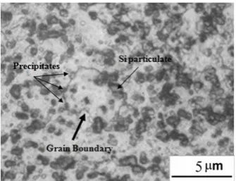
The reduction in the corrosion resistance of the PWHTed samples may be attributed to formation of precipitates such as Mg2Si and CuAl2 phases at grain boundaries of α-Al. Fig. 14
shows a high magnification optical micrograph for particulates along the grain boundaries at the center of the SZ of a PWHTed sample welded at a tool rotational speed of 1120 rpm and a welding speed of 112 mm/min. It was observed that both Si particulates and precipitates (such as Mg2Si and CuAl2) tend to precipitate at grain boundaries of
α-Al. The grain boundaries represent favourable sites for anodic activity compared with the grain matrix [12]. As a result, localized corrosion along the grain boundaries occurred. Increasing the tool rotational speed and/or reduction of the welding speed tends to increase the size of the precipitates located at grain boundaries and accordingly reduce the corrosion resistance of the SZ [21]. It is important to mention that dissolution of the precipitates decreases the sites for galvanic coupling and hence increases the corrosion resistance.
Fig.13. Micrographs of the microstructure at the centre of the PWHTed welded zone produced at several tool rotational and
welding speeds.
Fig.14. High magnification optical micrograph of SZ of a PWHTed sample showing the precipitation of particulates at
[image:6.595.46.283.468.580.2] [image:6.595.343.511.625.753.2]IV. CONCLUSIONS
1. The average size of the Si particles inside the stirred zone increases with raising tool rotational speed and reducing welding speed.
2. In both AW and PWHTed conditions, the hardness at the center of SZ was found to increase with increasing the welding speed and/or reducing the tool rotational speed. 3. The stirred zone of friction stir welded samples exhibited
enhanced resistance to intergranular corrosion behavior as compared to the base alloys. Moreover, post weld heat treatment reduced the corrosion resistance of the stirred zone.
4. The corrosion resistance of the stirred zone, at the center of the welded zones, was found to be reduced by increase of tool rotational speed and/or reduction of the welding speed.
5. Both the upper regions of the squeezed zone and the adjacent thermo-mechanically affected zone have corroded very severely.
REFERENCES
[1] C.S.Paglia, R.G.Buchheit, “A look in the corrosion of aluminium alloy friction stir welds,” Viewpoint Paper, Scripta Materialia, vol. 58, 2008, pp. 383–387.
[2] C.S. Paglia, K.V. Jata, R.G. Buchheit, “A cast 7050 friction stir weld with scandium: microstructure, corrosion and environmental assisted cracking,” Mater. Sci. Eng. A, vol. 424, 2006, pp. 196–204.
[3] R.W. Fonda, P.S. Pao, H.N. Jones, C.R. Feng, B.J. Connolly, A.J. Davenport, “Microstructure, mechanical properties, and corrosion of friction stir welded Al 5456,” Mater. Sci. Eng. A, vol. 519, 2009, pp.1–8. [4] D.A. Wadeson, X. Zhou, G.E. Thompson, P. Skeldon, L. Djapic Oosterkamp, G. Scamans, “Corrosion behaviour of friction stir welded AA7108 T79 aluminium alloy,” Corrosion Science, vol. 48, 2006, pp. 887–897.
[5] Jariyaboon M., A.J. Davenport, R. Ambat, B.J. Connolly, S.W. Williams, D.A. Price, “The effect of welding parameters on the corrosion behaviour of friction stir welded AA2024–T351,” Corrosion Science, vol. 49, 2007, pp. 877–909.
[6] Pao P.S., Gill S.J., Feng C.R., Sankaran K.K., “Corrosion-fatigue crack growth in friction stir welded Al 7075”, Scripta Materiala, 45, 2001, pp. 605-612.
[7] R. Braun, C. DalleDonne, G. Staniek, Materialwiss. Werkst., vol. 31, 2000, pp. 1017–1026.
[8] W. Hu, E.I. Meletis, Mater. Sci. Forum, vol. 331–337, 2000, pp. 1683–1688.
[9] Surekha K., Murty B.S., Prasad Rao K., “Effect of processing parameters on the corrosion behaviour of friction stir processed AA 2219 aluminium alloy”, Solid State Sciences, 11, 2009, pp.c907–917.
[10] Squillace A., De Fenzo A., Giorleo G., Bellucci F., “A comparison between FSW and TIG welding techniques: modifications of microstructure and pitting corrosion resistance in AA 2024-T3 butt joints,” J. Mater. Process. Technol., vol. 152, 2004, pp. 97–105. [11] Stefano Maggiolino, Chiara Schmid, “Corrosion resistance in FSW and in
MIG welding techniques of AA6XXX,” J. Mater. Process. Technol., 197, 2008, pp. 237–240.
[12] T.S. Mahmoud, A.M. Gaafer, T.A. Khalifa, “Effect of tool rotational and welding speeds on microstructural and mechanical characteristics of friction stir welded A319 cast Al alloy,” Mater. Sci. Technol., vol. 24, 5, 2008, pp. 553-559.
[13] H.J. Liu, H. Fujii, K. Nogi, “Microstructure and mechanical properties of friction stir welded joints of AC4A cast aluminium alloy,” Mater. Sci. Technol., vol. 20, 2004, pp. 399–402.
[14] Y.G. Kim, H. Fujii, T. Tsumura, T. Komazaki, K. Nakata, “Effect of welding parameters on microstructure in the stir zone of FSW joints of aluminium die casting alloy,” Materials Letters, vol. 60, 2006, pp. 3830-3837.
[15] W.B. Lee, Y.M. Yeon, S.B. Jung, “The improvement of mechanical properties of friction stir-welded A356 Al alloy,” Mater. Sci. Eng. A, vol. 355, 2003, pp. 154-159.
[16] ASTM Standard G110, Standard Practice for Evaluating Inter-granular Corrosion Resistance of Heat Treatable Aluminium Alloys by Immersion in Sodium Chloride + H2O2 Solutions, Vol. 03.02, 1998.
[17] A. Steuwer, M.J. Peel, P.J. Withers, “Dissimilar friction stir welds in AA5083–AA6082: The effect of process parameters on residual stress,” Mater. Sci. Eng. A, vol. 441, 2006, pp. 187–196.
[18] P. Cavaliere, R. Nobile, F.W. Panella, A. Squillace, “Mechanical and microstructural behaviour of 2024–7075 aluminium alloy sheets joined by friction stir welding,” Int. J. Machine Tools & Manufacture, vol. 46, 2006, pp. 588–594.
[19] Yutaka S. Sato, Seung Hwan C. Park, Masato Michiuchi, Hiroyuki Kokawa, “Constitutional liquation during dissimilar friction stir welding of Al and Mg alloys,” Scripta Materialia, vol. 50, 2004, pp. 1233–123. [20] Y. Nagano, S. Jogan, T. Hashimoto, “Mechanical properties of aluminum
die casting joined by FSW,” Proc. of the 3rd Int. Friction Stir Welding Symposium, Kobe, Japan, 2001, (CD-ROM).