ISSN: 1816-949X © Medwell Journals, 2019
A Novel Technique for Mean Filtering Algorithms Based on Systolic Architecture
Asmaa Hameed Rasheed
College of Engineering, Baghdad University, Baghdad, Iraq
Abstract: Mean filtering algorithms are widely used for image processing especially with image smoothing or denoising systems but its hardware implementation has many restrictions. Filtering Process needs image segmentation that was done by pipelined windowing technique to scan the processed image horizontally and vertically and the size of this window determines the length of mean filter. All pixels within the specified window are drawn simultaneously and processed together in each cycle. This process produces repeated calculations that leads to depleting more hardware which can be reduced highly if an efficient implementation method is used. Another important problem with traditional implementation method of this filter is the need of more I/O pins, since all pixel values of the processed window must be read at the same cycle. These I/O pins act as a big limitations that restrict the huge data manipulation systems when implemented with any high speed hardware platform. In this paper, two novel techniques were proposed to design and implement mean filtering algorithms, that ensure simplicity of the required hardware and efficiently improve processing time as well as the needed input pins are minimized highly by reading only the new pixels of the processed window, while keeping the remaining big part as it is without any change, since it is already prepared in previous cycle. The proposed techniques depend mainly on removing the repeated computations and cancellation of division operations which result in improving the processing efficiency and highly reduce the execution time to match real time requirements. Pipelining technique is also adopted here, with the second proposed technique, to activate parallel processing scheme. So, systolic architecture were used for further reduction in computation operations and to improve overall system execution time. The obtained results proved good enhancements in processing time especially for huge image size. The efficiency of implemented design was significantly improved for large filter length, that makes the proposed techniques very useful when dealing with huge data systems. The effect of Gaussian noise was tested for gray and colored images to compare the degradation of both of them with this type of noise.
Key words: Mean filtering, noise reduction, spatial filters, systolic array and parallel processing INTRODUCTION
Most image processing depend mainly on spatial filters that done by convolution masks. Image denoising, sharpening, blurring, edge detection and many other image processing necessitate using of masks. The mean filter is one of the most important masks that extensively used in different image processing (Jain, 1989).
Image filtering is the more important part in any image denoising system. The filtering process can be accomplished in frequency domain or in many cases, time domain filters can be very useful and mostly used for variety of image applications. Different spatial filters are used with image denoising system depending on the corrupted noise (Gonzalez and Woods, 2007).
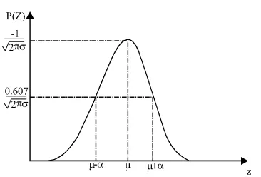
[image:1.612.335.518.475.599.2]If a Gaussian noise corrupt the original image, then mean filter is the most suitable one for noise removing in such cases. The efficiency of mean filter for noise removal with Gaussian noise refers to the fact that Gaussian noise values are concentrated around the mean as illustrated in Fig. 1 which shows the probability density function of Gaussian noise (Boncelet, 2000).
Fig. 1: Probability density function of Gaussian noise When large images is considered to be processed and large window sizes is dependent then any application need these filters can be quite time consuming. For example, the basic implementation of a mean filter for a 256×256 image with a 3*3 window size, needs more than 5×10 additions and also more than 65*10 divisions. We5 3
4+7+3+2+5+9+8+6+1 = 45
[image:2.612.338.515.94.169.2]45/9 = 5
Fig. 2: Windowing technique
[image:2.612.92.283.103.243.2]Mean filter: Mean filter is a linear digital filter that use a mask window of odd size to scan the image horizontally and vertically. The windowing operation is illustrated in Fig. 2.
Smoothing is done by reducing the variation in values for successive pixels. The smoothing operation is in fact equivalent to low-pass filtering that carefully smoothes any sudden change of pixel value by altering its value by average (mean) of its surrounding pixels. Smoothing filters or in more precisely mean filtering has a big area in noise removal and blurring of image processing (Kumar and Kumar, 2015).
Mean filtering is inherently a convolution operation as the mask is scanned the image until every pixel has been processed. Kernel is the base of convolutions process which is the shape and size of the surrounding neighbors that used for mean calculation. Large kernels are needed when smoothing must be deeply (Zhang and Li, 2014).
The traditional method, of mean filtering implementation is very simple but inefficient due to redundant and highly re-computations of the accomplished additions in the previous mask. The required number of additions is U*V*n and the needed2
division operations is U*V only. Thus, the number of additions and divisions are related directly to the image size, so, the problem of high consuming time appear clearly with large images which is the important factor for real time processing.
A major redundancy caused by re-computation of the sum of all pixel values of the specified window when the mask is moved from specified pixel to the successive one. As the mask is shifted by one pixel the sum of the new column in the mask window is needed only, since, the sum of all other columns is already computed for the previous pixel.
Mean filter implementation: As shown in Fig. 2, the window of size n*n firstly, scan the image horizontally
Fig. 3: Mean filtering process (a) Selected window and (b) Mean filtering process
and when the processed raw of the specified image is completed, then it begins a vertical path to process the second raw of the noisy image and so on.
The mean filter process is in factthe computing of average value (mean) of all pixels of the specified window. So, a summation of all these pixels must be obtained. The obtained sum is used to compute the average value of the current mask window. Then the value of the centered pixel in the processed window must be replaced with this average.
The window usually has a square shape but it can be any other shape that has a symmetry around its center such as circular window and rhombical window shape or any other symmetrical geometric form. The shape of the used window affect the number of pixels that must be processed for each window, thus this number may be reduced which results in reducing the number of addition operations. Figure 3 shows an example of 3×3 mean filter (taking specific window). The summation of all values in the given window is:
The mean (average ) value is:
The original value of the centered pixel is 9 and after mean filtering it was replaced by the mean of all nine values (Zhang and Li, 2014).
Traditional mean filtering algorithm: The classical method of mean filter implementation can be summarized in the following steps:
{
for every pixel in the image do;
select a specific window size around the pixel; sum all the values in the mask;
find the average of these values; replace the pixel value with mean value; }
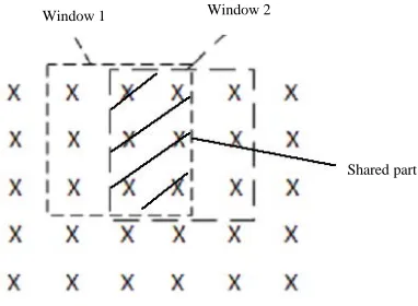
Window 1 Window 2
Fig. 4: Traditional hardware implementation of mean filter
Hardware implementation of mean filter: The ordinary The hardware implementation of this improved method for hardware implementation of mean filters is
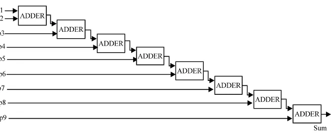
accomplished by scanning the window of specified size (n*n) over the entire image horizontally and vertically. The number of pixels of each window is equal to n multiplied by n(n*n pixels). All these pixels are entered simultaneously in parallel and summed together to compute the average of them. For n*n window size it is needed (n*n-1) adder and need n*n input pins from the recommended hardware that used as an implementation platform. Figure 4 shows traditional hardware implementation of 3*3 mean filter and it required eight adders. It is clear the number of required division operations in each step is only one.
MATERIALS AND METHODS
Proposed technique: The proposed technique depends on the fact that the new window is highly similar to the previous one (Zhang and Li, 2014) (for 3*3 mask window, similarity of 66.6%) and differs from it by only one column (also for 3*3 mask window, difference ratio is 33.3). Then there is no need to enter all the pixels of the new window but only the column that represent the difference part between the previous and next windows should be entered. As well as the summation of the big parts of the new window need not to be calculated next time, since, it is exist from the summation process of the previous window. In this way, the number of required adders will be reduced from (n*n-1) in the traditional technique to only (2*(n-1)) with proposed techniques.
The proposed techniques deal with clock sequencing to decide the suitable position of the input column.
{
If mod(clock seq/3) = 1 then assign entered column 1 to first stage; If mod(clock seq/3) = 2 then assign entered column 2 to first stage; If mod(clock seq/3) = 0 then assign entered column 3 to first stage; }
method is well illustrated in Fig. 5.
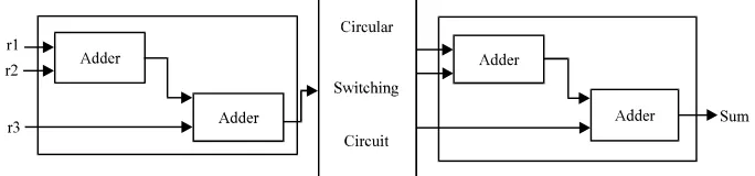
Proposed systolic technique: Systolic architecture are used for further reduction in addition operations. This proposed approaches convert the concurrent processing to sequential form as a pipelined stages, each stage responsible on part of the complete job and deliver its output to the next stage synchronized by a system clock (Wan, 1996; Evans and Amin, 1995). The number of additions can be minimized using pipelining technique, to only (n-1) addition operation. The number of input pins is also minimized from (n*n) pins to only (n) input pins with proposed techniques as shown in Fig. 6. The 5*5 mean filter design based on systolic array has been shown in Fig. 7.
Avoidance of division operation: In this research, we want to simplify the structure of hardware implementation of mean filtering process via. the assistance of systolic array. The hardware simplification process start by minimizing the number of used adders to find the summation of all pixels values within the specified window. Now, another try has been made to avoid the division operation that is essential to compute the mean (average) from the obtained sum. The division process as its obvious, need a complicated hardware, so an alternate method is used to avoid this division process.
Fig. 5: Proposed hardware implementation of mean filter
Fig. 6: Systolic design of mean filter with 3*3 filter length
Fig. 7: Systolic design of mean filter with 5*5 filter length
[image:4.612.135.477.99.179.2] [image:4.612.142.463.419.696.2]If the summation of the specified pixels vary between 1121-1129 then the average can be swing from 124.5-125.4 with step of 0.1 and all the values in this range can be considered as an integer of 125, since, any pixel value with floating point format can not be accepted for gray image. And when the sum vary between 1130-1138 the dependant average is 126 while when the sum is between 1112-1120, the average would be 124 and so on as illustrated in Fig. 8b.
S/W and H/W implementation remarks: The proposed techniques for mean filtering process using systolic array
can be implemented easily by replacing the adders with Fig. 9: Number of addition operations with respect to their digital equivalent circuits. The pipelined behavior is varying image size for different techniques solved by using systolic array design. The problem here
concentrate with the implementing of circular switching circuit and the reordering and latch circuit. The job of these two circuits can be established by using suitable S/W that executed with any high speed processor. The required software code can be summarized as follows:
PROCESS (clk) BEGIN
IF rising_edge (clk) THEN i <= i+1
if i = 1 THEN C1 <= SUM1 if i = 2 THEN
C2 <= SUM1 if i = 3 THEN
C3 <= SUM1 i <= 0 END PROCESS
RESULTS AND DISCUSSION
The two proposed methods were tested for 8-bit grayscale images and then extended for colored images filtration. Tested images have different sizes starting by 64*64 and ending with image size of 1024*1024. Mean filtering was applied using three different methods:
C Traditional method
C Proposed method
C Developed method using systolic array architecture
For all these methods the testing is considered for varying masking window size sewing from 3*3-11*11 window size. The formulated used number of adders for traditional and proposed methods are summarized in Table 1. This table presents also the number of required division operation for each design method.
[image:5.612.327.522.101.232.2]To declare the comparison among the three tested methods, the used numbers of adders were computed to
Fig. 10: Number of addition operations with respect to different techniques for 1024*1024 image size single window for each method with respect to different sizes of masking window vary from 3*3 and ending with 11*11 window size as illustrated in Table 2.
Different images with variable size ranged from 64*64 to 1024*1024 were processed in this work, the above calculations were repeated for each one and presented in Table 3.
Processing time was computed for mean filter with different filter length for each implemented method in this paper (traditional and proposed methods). Table 4 presents the computed values of this processing time.
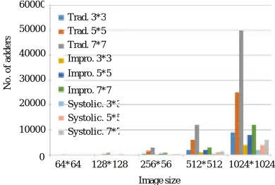
The varying number of adders for each image by applying all the implemented methods in the present research are shown in Fig. 9 while Fig. 10 repeat the same graph but for the image of size 1024*1024 only.
The increasing number of addition operations according to window size for the three tested methods is will illustrated in plot of Fig. 11 and the inverse plot that shows the number of addition operations with respect to these implementing methods against different window size is shown in Fig. 12 that applied to largest image also.
The plot of execution time against varying window size for the largest test image which have a size of 1024*1024 is shown in Fig. 13.
64*64 128*128 256*56 512*512 1024*1024
Image size 60000 50000 40000 30000 20000 10000 0
No. of adders
[image:5.612.326.524.271.394.2]Table 1: Number of adders for traditional and proposed methods
Technique/Operators Traditional method Improved method Systolic method Advanced method Advanced systolic
Adders n*n-1 2*(n-1) n-1 N 1
Dividers 1 0 0 0 0
Table 2: The number of required adders according to filter length for different implementing techniques
Used method/Window size Traditional method Proposed method Proposed method with systolic array
3*3 8 4 2
5*5 24 8 4
7*7 48 12 6
9*9 80 16 8
11*11 120 20 10
Table 3: Approximated number of required addition operations for different image size with different design techniques
Traditional method Proposed method Proposed method with systolic array
--- ---
---Used method/Image size 3*3 5*5 7*7 3*3 5*5 7*7 3*3 5*5 7*7
64*64 33*103 99*103 20*104 16*103 32*103 49*103 8*103 16*103 24*103
128*128 13*104 40*104 79*104 65*103 13*104 20*104 32*103 65*103 98*103
256*256 53*104 16*105 3*106 26*104 53*104 79*104 13*104 26*104 39*104
512*512 2*106 6*106 12*106 1*106 2*106 3*106 5*105 1*106 15*105
1024*1024 9*106 25*106 50*106 4*106 8*106 12*106 2*106 4*106 6*106
Table 4: Processing time for varying filter length with respect to different techniques
Used method/Window size Traditional method Proposed method Proposed method with systolic array
3*3 0.032768 0.0182044 0.010113
5*5 0.055945 0.019980 0.011100
7*7 0.080372 0.021150 0.011750
9*9 0.125998 0.026249 0.014583
11*11 0.183752 0.031681 0.017600
Fig. 11: Number of addition operations with respect to different techniques for varying filter length for an image of size 1024*1024
[image:6.612.94.276.546.684.2]Fig. 12: Number of addition operations with respect to different filter length with different techniques for an image of size 1024*1024
Fig. 13: Processing time for varying filter length with respect to different techniques
The plots that shows the big arising in number of addition operations with respect to image size for different window size are shown in Fig. 14-16 for traditional, improved and systolic method, respectively. The curves of Fig. 15 and Fig. 16 have the same shape but with different values.
Fig. 14: Number of addition operations with respect to Fig. 15: Number of addition operations with respect to varying image size for traditional technique varying image size for improved technique according to different filter length according to different filter length
[image:7.612.171.426.275.438.2]Fig. 16: Number of addition operations with respect to varying image size for systolic technique according to different filter length
Fig. 17: Continue
[image:7.612.179.413.478.712.2]Fig. 17: Performance of implemented mean filter with gray images (a) Original images, (b) Noisy images and (c) Filtered images
Fig. 18: Continue
(a) (b) (c)
[image:8.612.138.461.297.698.2]Fig. 18: Performance of implemented mean filter with colored images, (a) Original images, (b) noisy images and (c) Filtered images
CONCLUSION Finally, the effect of Gaussian noise on gray images Two different techniques were proposed in the
present work for mean filtering system design, to simplify hardware complexity, minimize processing time and improve overall system performance.
The reduction of hardware complexity can be achieved due to the efficient minimization in the required numbers of adders. The proposed improved method reduces the used number of adders from (n*n-1) to 2*(n-1) and the proposed systolic technique consumes as less as (n-1) adders only. If a storage element is used to keep the previous calculated sum in each step then further reduction can be gained to get (n) adders for the proposed improved method.
The division operations have been canceled in the proposed design method which results of more reduction in the used hardware as well as high improvements of processing time can be gained. This cancellation is done by storing the expected integer results of a division operation for different ranged sums.
The proposed methods and the implemented systems presented in this work were tested for different image sizes with varying filter length ranged from 3*3 to 11*11. The obtained results and plots ensure excellent improvements with respect to hardware design. Execution time was effectively reduced with the proposed techniques especially for large images, that encourage to depend the proposed systems for many real time applications of image processing.
The filtered images, that differ clearly in their complicated characteristic details, show that the mean filter behaves better with images of complicated details.
is greater than its effect on colored ones, but mean filter shows best performance with colored images than the enhancement achieved for gray images.
REFERENCES
Boncelet, C., 2000. Image Noise Models. In: Handbook of Image and Video Processing, Bovik, A.L. (Ed.). Academic Press, San Diego, California, USA., ISBN:0-12-119790-5, pp: 325-335.
Evans, D.J. and S.A. Amin, 1995. Systolic algorithms for digital image filtering. Parallel Comput., 21: 109-119. Gonzalez, R.C. and R.E. Woods, 2007. Digital Image
Processing 3rd Edn., Prentice Hall, New York, ISBN-13: 9780131687288.
Jain, A.K., 1989. Fundamentals of Digital Image Processing. Prentice-Hall, Upper Saddle River, New Jersey, USA., ISBN:9780133325782, Pages: 569. Kumar, N.R. and J.U. Kumar, 2015. A spatial mean and
median filter for noise removal in digital images. Intl. J. Adv. Res. Electr. Electron. Instrum. Eng., 4: 246-253. Rakshit, S., A. Ghosh and B.U. Shankar, 2007. Fast Mean Filtering Technique (FMFT). Pattern Recogn., 40: 890-897.
Wan, C., 1996. Systolic algorithms and applications. Ph.D Thesis, Loughborough University, Loughborough, England, UK.
Zhang, P. and F. Li, 2014. A new adaptive weighted mean filter for removing salt-and-pepper noise. IEEE. Signal Process. Lett., 21: 1280-1283.