PROCEEDINGS OF SPIE
SPIEDigitalLibrary.org/conference-proceedings-of-spie
High resolution, wide field of view,
real time 340GHz 3D imaging radar
for security screening
Duncan A. Robertson, David G. Macfarlane, Robert I.
Hunter, Scott L. Cassidy, Nuria Llombart, et al.
Duncan A. Robertson, David G. Macfarlane, Robert I. Hunter, Scott L.
Cassidy, Nuria Llombart, Erio Gandini, Tomas Bryllert, Mattias Ferndahl,
Hannu Lindström, Jussi Tenhunen, Hannu Vasama, Jouni Huopana, Timo
Selkälä, Antti-Jussi Vuotikka, "High resolution, wide field of view, real time
340GHz 3D imaging radar for security screening," Proc. SPIE 10189, Passive
and Active Millimeter-Wave Imaging XX, 101890C (11 May 2017); doi:
High resolution, wide field of view, real time 340 GHz
3D imaging radar for security screening.
Duncan A. Robertson*
1, David G. Macfarlane
1, Robert I. Hunter
1, Scott L. Cassidy
1, Nuria
Llombart
2, Erio Gandini
2, Tomas Bryllert
3, Mattias Ferndahl
4, Hannu Lindström
5, Jussi Tenhunen
5,
Hannu Vasama
5, Jouni Huopana
6, Timo Selkälä
6, Antti-Jussi Vuotikka
61
University of St Andrews, SUPA School of Physics & Astronomy,
St Andrews, Fife KY16 9SS, Scotland
2
Technical University of Delft, Delft, Netherlands
3
Wasa Millimeter Wave AB, Gothenburg, Sweden
4
GotMIC AB, Gothenburg, Sweden
5
VTT Technical Research Centre of Finland Ltd., Oulu, Finland
6
Global Boiler Works Oy, Oulu, Finland
ABSTRACT
The EU FP7 project CONSORTIS (Concealed Object Stand-Off Real-Time Imaging for Security) is developing a demonstrator system for next generation airport security screening which will combine passive and active submillimeter wave imaging sensors. We report on the development of the 340 GHz 3D imaging radar which achieves high volumetric resolution over a wide field of view with high dynamic range and a high frame rate. A sparse array of 16 radar transceivers is coupled with high speed mechanical beam scanning to achieve a field of view of ~ 1 x 1 x 1 m3 and a 10 Hz frame rate.
Keywords: Radar, submillimeter wave, security, FMCW, imaging.
1.
INTRODUCTION
Submillimeter wave 3D radar imaging is suitable for the detection of concealed objects in security applications such as next generation walk-by screening. The principal challenges in this are achieving high volumetric resolution over a relatively wide field of view, with high dynamic range, and at a sufficiently high frame rate to cope with dynamic scenes.
The EU FP7 project CONSORTIS (Concealed Object Stand-Off Real-Time Imaging for Security)1 is addressing this need and is developing a demonstrator system for next generation airport security screening which will combine passive and active submillimeter wave imaging sensors.
Here we report on the development of the 340 GHz 3D imaging radar which achieves high volumetric resolution over a wide field of view with high dynamic range and a high frame rate. A sparse array of 16 radar transceivers is coupled with high speed mechanical beam scanning to achieve a field of view of ~ 1 x 1 x 1 m3 and a 10 Hz frame rate.
The radar uses an FMCW homodyne architecture with frequency multiplying transceivers which exploit self-mixing multiplier technology, dispensing with the need for explicit duplexing components. The transceivers are driven by a wideband (~10%) 16 channel chirp generator which exhibits excellent channel balance and amplitude flatness. State-of-the-art wide field of view Dragonian mirror optics, in combination with the beam scanning optomechanics, yields high spatial resolution, low scan loss and low aberration over the field of view at relatively short range. High speed data acquisition and real time signal processing complete the concept demonstrator.
Section 2 describes the CONSORTIS system, section 3 the radar subsystem, section 4 the radar optics, section 5 the radar processor. Section 6 then gives some initial results, and the conclusions are given in section 7.
2.
SYSTEM OVERVIEW
[image:3.612.132.474.201.414.2]The CONSORTIS system is currently nearing the end of the manufacturing and integration phase and a 3D CAD model of the system is shown in Figure 1. It consists of an enclosure tower which houses the 340 GHz radar in the top section above the dual-band (250 / 500 GHz) cryogenically cooled passive imager in the lower section. As passengers pass by the system, data is collected from both primary sensors and a Support Sensor which measures the subject’s pose and position to aid data analysis. Passenger flow is controlled by a Passenger Control Subsystem which ensures only one person is being imaged at a time. The sensor data are passed to an Automatic Anomaly Detection subsystem which analyzes the data and presents an indication on the operator’s interface whether the passenger is clear to proceed or requires further manual screening.
Figure 1. CONSORTIS system CAD model.
3.
RADAR CIRCUIT
The radar uses a homodyne FMCW architecture in which frequency chirps generated in the microwave range are multiplied up to the carrier frequency and the reflected signals are mixed down to a raw intermediate frequency (IF) range in the tens of MHz. The frequency multiplication factor is x32. To achieve range bins of 0.5 cm for fine feature discrimination the transmitted chirp bandwidth is 30 GHz and the chirp duration is 40.96 µs. Since there is no need to detect targets in all ranges down to zero, a range-offset downconversion receiver isolates the range swath of interest and downconverts it to baseband, thus minimizing the sampling requirements. The major building blocks of the radar circuit are described on the following sections.
3.1 Wideband Chirp Generator
Wideband frequency chirps are generated at X-band prior to multiplication in the transceiver modules. The chirp generator is required to produce wideband chirps (0.94 GHz, 9% bandwidth) at 10.6 GHz with high linearity and low phase noise. Chirps are generated using an Analog Devices AD9914 direct digital synthesis (DDS) evaluation board clocked at 3.5 GHz. The DDS eval board's proprietary USB interface has been disabled and replaced with a custom USB daughter board which allows the relevant DDS control parameters to be manipulated programmatically from within the radar control software. The chirps are upconverted onto a microwave stable local oscillator (STALO) signal, filtered, doubled and filtered again. As 16 outputs are needed to drive the transceivers, each of which requires a +12 dBm input level, the chirp generator also incorporates a 1 W amplifier and 16-way power divider network. Figure 2 (left) shows the chirp generator assembly on the bench. The output power versus frequency for all 16 channels is shown in Figure 2 (right) and exhibits excellent channel balance and flatness of ±0.5 dB.
Radar
:ya&x
«£
_
-15
-E14.5
-co a 14
.-3 1.-3.5 c. 13 c, 12.5 ó 12 v 10.5 10 1015
111/11-__1Mi-
---
---
---
10 25 10 35 10 45 10 55 10 65 10 75 10 85 10 95 1105CG output frequency [GHz]
+8 +7 +6 +5 +4 +3 +2 +1 1 2 3 4 5 6 7 8 6
4
r
-.
'.
; _ __`_r,:
i-`- . s
.r-/-
.
I`J
_ ;
- ,`'
`.1%
y
TXRx-14 -TxRx-17 TxRx-18 TxRx-19
-
-TxRx-20 -TxRx-22
-TxRx-23 -TxRx-24-TxRx-06 TxRx-10 TxRx-8
-TxRx-05
,
-TxRx-11 -TxRx-12
-TxRx-13.-, -mo 2 tv ó. -2 -4 eco -6 -8 10
325 330 335 340 345 350 355
[image:4.612.72.540.75.243.2]Transmit frequency GHz
Figure 2. Chirp generator (left) and output frequency response for all 16 channels showing excellent flatness (right).
3.2 Self-Mixing Multiplier Homodyne Transceivers
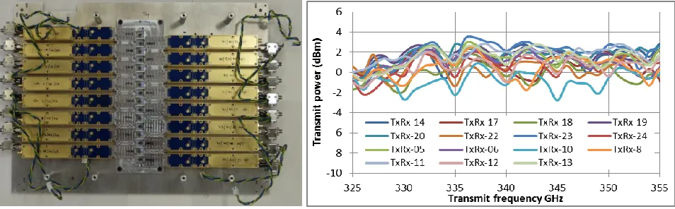
The transceiver consists of a x32 frequency multiplication chain in the sequence: x8 MMIC – x2 Schottky – x2 Schottky. The key novelty in this design is the use of a self-mixing doubler as the last stage: this acts as both the final doubler in the transmit path but also acts as a sub-harmonic mixer on receive2. This function is realized by using a balanced circuit configuration of two diode pairs which provides immunity to local oscillator (LO) noise. Internal waveguide branch-line coupler hybrids provide the necessary phasing at the LO and RF ports and the IF is coupled via a transformer which also provides the connection for DC bias of the diodes. Figure 3 (left) shows all 16 transceiver modules disposed in two 8 channel sub-arrays, mounted in the focal plane array including the feedhorns.
The transceiver output power is quite flat over the full 30 GHz bandwidth, yielding 1.0 ±1.4 dBm – Figure 3 (right), which is desirable for high fidelity radar measurements. Inevitably there is compromise with this design compared with having separate multiplier and mixer components and the receive conversion loss is around -19.0 ±1.4 dB. However, in the envisaged security imaging applications, signal-to-noise ratio is rarely the limiting factor in target detection. The compact form factor of the modules and their significant advantage of not requiring an external transmit-receive duplexer (either in waveguide or quasi-optics) makes them ideal for assembly into 1-D or 2D arrays, suitable for imaging.
Figure 3. Focal plane array showing 16 gold and blue transceiver modules (left) and output frequency response for all 16 transceivers (right).
3.3 Range-Offset Downconversion Receiver
[image:4.612.68.545.445.593.2]AZ'S
41: .
C e j..
^Molt :0 No
mi 't 35 30 25 ÿ 20 C m 15 10 5 0
o 1 2 3 4 5
IFFreq [MHz]
6 7 8
-#01
-#02
-#03
-#04
-#05
-#06
-#07
-#08
-#09
-#10
-#11
#12-#13
#14-#15
-#16
A downconversion receiver circuit was designed to perform this task and sixteen individual receiver PCBs were fabricated. In each receiver a custom bandpass filter selects frequencies in the 19 – 25 MHz range and these are amplified then downconverted against an 18 MHz local oscillator to a baseband range of 1 – 6 MHz which is also amplified. The receiver circuit concludes with an anti-alias lowpass filter prior to the ADC. The 18 MHz LO signals are generated on a separate PCB by a crystal oscillator whose output is power divided 16 ways. The 16 receiver PCBs and the LO PCB are shown in Figure 4 (left). All sixteen receiver PCBs were characterized and their measured conversion gain frequency response (18.1 – 26 MHz input, 0.1 – 8 MHz output) shows excellent channel-channel balance – Figure 4 (right).
Figure 4. 16 receiver PCBs and LO PCB on radar front end assembly (left) and receiver conversion gain frequency response for all 16 PCBs showing excellent channel balance (right).
4.
OPTICS
The requirements of the optics are that they should focus the beam from each transceiver to a tight spot (~1 cm) at the focal distance (~2.5 m) with adequate depth of focus and scan over a wide field of view (FoV) with low aberration and low scan loss. Multiple transceivers are disposed in a large format, sparse, linear focal plane array to enable parallel acquisition. The optics must also perform fast beam scanning in two dimensions to achieve full spatial sampling at the desired frame rate of 10 Hz and finally the whole FoV must be steerable to follow the movement of the subject. To achieve these goals, an optical system of five mirrors is used which is described in more detail below. Coupling between the transceivers and free space is achieved with smooth-walled feedhorns which are described in the subsequent section.
4.1 Focussing and Beam Scanning Optics
In the CONSORTIS system, the subject is at a relatively short range (2 – 3 m) and thus subtends a relatively large angular FoV. The optical architecture that guarantees the largest FoV for multiple-feed illumination compared to other dual-reflector systems is the Dragonian configuration3. This is due to the small magnification of the Dragonian which brings the benefits of reduced aberrations and spillover loss. We have thus implemented a Dragonian focusing mirror pair, illuminated by the line array of feedhorn-equipped transceivers.
Due to the relatively short focal distance, the mirror sizes are modest (25 – 30 cm) so the scanning optics can follow the focusing optics. As noted above, scanning in two dimensions is needed to fully sample the image so two scanning mechanisms are required. To scan in the direction orthogonal to the transceiver array we selected to perform a fast quasi-linear scan using a rotating double-disc scanner4. This is a type of Lissajous scanner which traces out a long, thin figure-of-eight pattern which approximates a linear scan. The advantage of this approach is that the mechanical motion is rotary rather than reciprocating so high scan speeds can be achieved (45 Hz). To fill in the scan pattern in the slow axis, the primary mirror of the Dragonian pair reciprocates at 5 Hz (a.k.a. the flip-flap mirror).
Finally, to direct the beam towards the subject as they walk past the system, a large oval mirror is used to pan the beam in the azimuthal direction (78° in 2 s). As the radar sits above the radiometer, the radar beams are tilted downwards by 12.5 ° so the FoVs of the two sensors overlap. A ray trace diagram of the radar optics is shown in Figure 5 along with a photo of the five mirrors viewed approximately from the position of the transceiver array.
16x Rx PCB
[image:5.612.68.546.174.324.2]w
c -25
o
ÿ- -30
w
ce -35 -40 -45 -50
CST E 340
340 SH01 340 SH02
-ST H 340 _
340 SHO1
340 SH02
-45- 40- 35- 30- 25- 20 -15 -10 -5 0 5 10 15 20 25 30 35 40 45
Angle [deg]
[image:6.612.96.527.77.251.2]Figure 5. Ray trace diagram of the radar optics (left) and photo showing main optical components (right).
4.2 Feedhorns
The key target performance metrics for the feedhorns were that they should have a symmetric -10 dB beamwidth of 9.8° ± 5% over a 30 GHz bandwidth centered at 340 GHz and as high a Gaussicity as possible (>98%). Additionally, as 16 horns were required for the focal plane array, a relatively low cost method of manufacture was desirable. A smooth-walled spline profile horn design was thus developed and fabricated in E-plane split block by direct machining. The horns have WM-650 (650 x 325 µm) rectangular waveguide inputs with integral transitions to circular waveguide, a Ø6.75 mm aperture and are 36 mm long5 – Figure 6 (left)
The spline profile part of the horn was simulated in CORRUG† and the full structure including the rectangular-to-circular transition was then verified in CST‡. The predicted -10 dB beamwidth is very close to requirements and the Gaussicity exceeds 99.2% over the full 30 GHz bandwidth, exceeding that reported for similar designs
Figure 6. Pair of smooth-walled spline profile horns (left) and E- and H-plane far-field antenna patterns at 340 GHz comparing CST simulations and measurements of two sample horns.
The far-field patterns were measured in the E- and H-planes at low-, mid- and high-band frequencies and results for two sample horns at 340 GHz are shown in Figure 6 (right) alongside CST simulations. The agreement between measurement and simulation is excellent down to below -40 dB. The mainlobe shows some low level asymmetry below -15 dB, probably due to the smooth-walled nature of the horn, and the sidelobe level is below -30 dB. The repeatability between the two units measured is excellent which verifies the split-block direct machining approach is appropriate for manufacturing such horns in quantities suitable for imaging arrays.
† S.M.T. Consultancies Ltd. http://www.smtconsultancies.co.uk/ ‡
Computer Simulation technology AG https://www.cst.com/
Pan mirror DD1
DD2 Secondary
[image:6.612.109.507.404.559.2]ojo
5.
PROCESSOR
The radar is controlled by a mid-range consumer PC (DELL Optiplex XE2) running the Windows 7 64-bit operating system. Control code is written in C using the National Instruments LabWindows/CVI programming environment. Radar control is achieved over USB via a 7-port hub. The USB modules in the head are:-
1. Customized DDS eval board (for DDS chirp programming)
2. Stepper motor controller for the pan axis
3. Two linear motor controllers for the slow scan axis
4. Motor controller for the fast scan axis
5. Microcontroller for control of fast axis motor speed
6. NI USB-6251 Multifunction DAQ
The NI DAQ unit performs multiple functions:-
1. Master transmit switch operation
2. 16 channel RF switch control
3. Master transmit power monitor detector
4. 16 channel power monitor detectors
5. Analog waveform control for slow axis motor
6. Fast axis encoder signal distribution for triggering and frame synchronization
The 16 baseband output signals are sampled by a pair of GageScope Octopus 16-bit 25 MS/s ADC cards in a PCIe chassis mounted in the radar head. Data is transferred to the host PC by a 5 m long PCIe cable. Burst acquisition of chirp outputs is triggered by an encoder driven from the fast axis motor and 1024 data points are sampled per chirp (40.96 µs), yielding 512 range bins for every line of sight. With a chirp bandwidth of 30 GHz and range bins of 0.5 cm, the full range swath covers 2.56 m. Spatial sampling consists of 100 pixels per horizontal line and a total of 144 lines vertically (9 for every transceiver). With 14,400 lines of sight per frame, the processor has to capture and compute 144,000 1k FFTs per second when the imager is running at the full 10 Hz frame rate. The total raw sample rate at 10 Hz frame rate is thus 147.4M samples per second. Processing this high data rate in real time (each frame processed in less than one frame duration of 100 ms) places significant demands on the processing code. The code architecture uses multi-threading on the multicore processor and is based on the successful parallelized approach developed at St Andrews6, 7.
The entire radar system is powered from a custom built, 4U 19” rackmount power supply unit which includes 8 individually regulated DC outputs, direct mains pass-through and switched mains – Figure 7. The complete system can thus be powered from a single 220 Vac 13A wall socket and consumes 550 VA.
[image:7.612.98.505.532.678.2]
Figure 7. Radar power supply unit.
Umbilical
ON/OFF
Motor switch ETI
1
ti
6.
INITIAL RESULTS
[image:8.612.77.537.121.356.2]The radar is currently undergoing testing and characterization in parallel with the development of the control code. Figure 8 shows the radar subsystem and the laboratory test set up.
Figure 8. Radar subsystem (left) and laboratory test set up (right).
Characterization to date has centered on confirming the FoV coverage, beam pointing and beam scanning performance. The focused spots from each transceiver are spaced at intervals of 6 cm in a line up the focal plane, which is tilted back at 12.5° to the vertical. Miniature corner cubes (square trihedrals with a 4 mm edge length) are used as bright sub-beamwidth targets and have a reasonable tolerance to angular pointing. The FoV at the focal plane is 100 cm wide by 96 cm high – Figure 9 (left). The range extent measured by the radar is defined by a combination of the optical depth of focus and the bandpass filter in the receiver. The measured range extent is 1 m centered on the focal plane.
Synchronization of the fast and slow scan axes is achieved via the encoder mounted to the fast axis rotary motor. Left-to-right and Left-to-right-to-left horizontal scans have been aligned through careful positioning of the encoder datum. Data acquisition is synchronized to the start of a frame using the rotary encoder Z pulse. Frames start at the bottom left and scan to the right and up towards the top right hand corner, and then back down again, as viewed by the radar.
Figure 9. FoV overlay (left) and a corresponding early example intensity image of a metallized mannequin (right).
PSU
~2.3 m
[image:8.612.137.476.505.686.2]11,1i1
P,y
d
,il
Figure 9 (right) shows an example of an early intensity image of a metallized mannequin. Areas of high intensity correspond to specular reflections from regions of the surface which are locally normal to the beam. The raised noise floor across the center of the image is due to two adjacent transceivers having slightly higher noise levels than others. There is residual distortion in this image as it is a simple projection of the raw data and has not been corrected for the angular scanning or the subtle differences in the sampling of alternate lines.
Work is currently ongoing to compensate for the frame rate dependent fall-off in elevation scanning angle achieved with the slow axis flip-flap mirror. The deviation of the driving linear motors as a function of frame rate has been characterized and a pre-distorted drive waveform used to compensate for the distortion, thus ensuring the full elevation scan range is achieved per transceiver.
The mannequin has been useful for initial testing at slow acquisition rates but suffers from having a very high reflectivity due to the metallization and this can yield unrealistically bright reflections. As the beam scanning and data acquisition developed we have begun collecting imagery of people and some examples are shown in Figure 10. Intensity images are presented as front or side projections of the 3D data cube, without correction of the angular scanning. Range calibration, to reduce the effect of residual chirp nonlinearity has not been applied to these images. Image data can be captured at up to 10 Hz but is currently processed offline in MATLAB for display in the formats shown.
[image:9.612.78.533.261.613.2]
Figure 10. Example images of two different people. Intensity image front view (top left), side view (top middle) and snapshot of 3D point cloud (top right) acquired at 1 Hz frame rate, and intensity image front view (bottom left) and side view (bottom right) acquired at 5 Hz frame rate. The intensity range is 35 dB in all images.
7.
CONCLUSIONS
We have presented the 340 GHz 3D imaging radar being developed for the EU FP7 CONSORTIS project. The radar uses 16 transceiver channels and high speed optomechanical beam steering to achieve a frame rate of 10 Hz with a volumetric field of view of ~1 x 1 x 1 m3. The combination of Dragonian focussing optics and a 30 GHz chirp bandwidth yields a voxel resolution of ~1 cm3. Key technologies employed in the radar have been reviewed and a selection of initial imagery presented.
Testing and characterization of the radar will soon be complete after which it will be integrated with the dual-band passive submillimetre wave imager into the system enclosure. The system aims to prove technology for use in next-generation airport security screening.
8.
ACKNOWLEDGEMENTS
Part of the research leading to these results has received funding from the European Union Seventh Framework Programme (FP7/2007-2013) under grant agreement no. 312745. The authors are very grateful to all our colleagues in the CONSORTIS project for their ongoing support and collaboration.
REFERENCES
[1] CONSORTIS website: http://consortis.eu/
[2] Dahlbäck, R., Bryllert, T., Granström, G., Ferndahl, M. Drakinskiy, V. and Stake, J., “Compact 340 GHz homodyne transceiver modules for FMWC imaging radar arrays,” IEEE MTT-S International Microwave Symposium (IMS), 1 – 4 (2016)
[3] Gandini, E. and Llombart, N., “Toward a real time stand-off submillimeter-wave imaging system with large field of view: quasi-optical system design considerations,” Proc. Of SPIE 9462, 946205, 1 – 12 (2015)
[4] Lettington, A.H., Alexander, N.E. and Dunn, D., “A new opto-mechanical scanner for millimeter and sub-millimeter wave imaging,” Proc. of SPIE 5789, 16 - 23 (2005)
[5] Robertson, D.A., McKay, J.E., Hunter, R.I., Speirs, P.J. and Smith, G.M., “High Gaussicity feedhorns for sub-/ millimeter wave applications”, 41st Int. Conf. Infrared, Millimeter, and Terahertz waves (IRMMW-THz), 1 – 2 (2016)
[6] Robertson, D.A., Marsh, P.N., Bolton, D.R., Middleton, R.J.C., Hunter, R.I., Speirs, P.J., Macfarlane, D.G., Cassidy, S.L., and Smith, G.M., “340 GHz 3D radar imaging test bed with 10 Hz frame rate.”, Proc. SPIE 8362, Passive and Active Millimeter-Wave Imaging XV, 836206, (2012)