MULTIPLE CHANNEL CROSSTALK REMOVAL USING
LIMITED CONNECTIVITY NEURAL NETWORKS
M.P.Craven, K.M.Curtis and B.R. Hayes-Gill
University of Nottingham, Department of Electrical and Electronic Engineering, University Park, Nottingham, NG7 2RD, UK. Tel: +44 115 9515536 Fax: +44 115 9515616 E-mail: mpc@eee.nott.ac.uk
ABSTRACT
Limited connectivity neural network architectures are investigated for the removal of crosstalk in systems using mutually overlapping sub-channels for the communication of multiple signals, either analogue or digital. The crosstalk error is modelled such that a fixed proportion of the signals in adjacent channels is added to the main signal. Different types of neural networks, trained using gradient descent algorithms, are tested as to their suitability for reducing the errors caused by a combination of crosstalk and additional gaussian noise. In particular we propose a single layer limited connectivity neural network since it promises to be the most easily implemented in hardware. A variable gain neuron structure is described which can be used for both analogue and digital data.
1. INTRODUCTION
This paper is concerned with the use of mutually overlapping sub-channels for communication of multiple signals in electronic systems. Such a method was originally intended for the task of reducing the pin-out in VLSI inter-chip connections using Frequency Division Multiplexing (FDM), since the signals generated by a set of outputs may be combined on-chip and transmitted off-chip via a single wire. However, the method is equally applicable to the general case of crosstalk in multiple channel communications, with or without FDM. Previous work carried out at the University of Nottingham has demonstrated that multiple sub-channel analogue FDM is feasible only if deliberate overlapping of the sub-channels is allowed[1]. This overlapping inevitably introduces adjacent channel (or cross-channel) interference which reduces the SNR in the receiver unless steps are taken to remove it. A multiple channel communication model is described by Van Etten[2] which uses an MxM interference matrix so that received signals are linear combinations of the wanted and interfering signals. In this paper the interference is considered to be resulting entirely from nearest adjacent sub-channels and the amount of interference is a fixed fraction ε of each of the adjacent signals, which is called the fractional crosstalk (or fractional overlap) parameter. This situation would arise in an FDM channel when receiver filter responses are overlapped by equal amounts, or in some kinds of multicore cable. It is necessary to examine the increase in error in the received signals caused by increasing this crosstalk, and thus compare methods for reducing the errors.
Consider a channel with M transmitters with signals denoted by the vector x at a particular time. Thus the M
received signals denoted by the vector y are given by y = R x where R is the interference matrix of form,
(1)
shown here for M=5.
2. NEURAL NETWORK ERROR REDUCTION The aim is to find the inverse of R in order to regain (or equalise) the original signals. This is can be written in the form of a single layer feedforward neural network, where the elements of the inverse matrix are approximated as closely as possible by the weights of the network i.e. z = W y where W ≈ R-1, so z ≈ x. Direct calculation of the inverse is possible, and a result is obtained analytically except for certain values of ε which make the matrix singular. The weights wji are also readily calculated iteratively by the µ-LMS algorithm[3] as follows,
∆wji = 2µ (xi - zi)yj (2)
However, such a network requires M2 weights so a hardware architecture based on this scheme would scale rather badly with M. It has been demonstrated[4] that the area of a fully connected neural network architecture scales with order M3. The use of limited connectivity neural networks are thus proposed here where many of the weight matrix elements are zero.
2.1. Limited connectivity architecture
A limited connectivity architecture simplifies the network and allows the number of weights to be scaled linearly with M, which is important both in reducing the overall size of network and in providing a extendable modular structure. In the case where connectivity is limited to three receivers, the number of weights required is ≈3M and the optimum weight matrix has the form,
(3)
which is a limited connectivity neural network with 3 inputs per neuron. Clearly, W will only be an
W
w w
w w w
w w w
w w w
w w
=
+
− +
− +
− +
−
0 1
1 0 1
1 0 1
1 0 1
1 0
0 0 0 0 0
0 0
0 0 0 0 0
R=
1 0 0 0
1 0 0
0 1 0
0 0 1
0 0 0 1
ε ε ε
ε ε ε ε
approximation to R-1. For clarity, the signal to be corrected is given index 0 and the other transmitted signals are indexed ±1 and ±2. The input signals to each neuron yj comprise the received signal from the original receiving node and its nearest neighbours, which are then multiplied by the weights wi and summed to give output z0. Thus, a maximum of 5 transmitted signals xi have an effect on any one received signal.
2.2. Analogue data
Error correction can be carried out independently for each neuron by finding its optimal weights. In the case of analogue signals, the output must follow the amplitude of the corresponding transmitted signal node as closely as possible, in spite of the crosstalk errors introduced, for an arbitrary combination of signals from the 5 transmitting nodes. In this implementation the five transmitted values were random numbers in a uniform distribution of range [0,V] (representing an analogue voltage range of 0 to V volts). Before the correction network the error is,
(y0-x0) = ε x-1 + ε x+1 (4)
and at the output of the neuron, the error expression is,
(z0-x0) = (w0+ε w-1 + ε w+1-1)x0 + (w-1+ε w0)x-1
+ (w+1+ε w0)x+1 + ε w-1x-2+ ε w+1x+2 (5)
The expectation E[Z0-X0] and variance Var[Z0-X0] can then be derived and minimised (by partial differentiation with respect to w0 and w1, setting w+1=w-1=w1 since the mean input vector is symmetrical) to yield the optimal values of w0 and w1 which are found to be,
w0
2
2
3 2 1 2 3 8 7
= − − + − +
( )
( )( )
ε ε
ε ε ε w1 2
4 3
1 2 3 8 7
= −
+ − +
ε ε ε ε ε
( )
( )( )
(6)
The weights may also be found iteratively as before by approximate steepest descent using the µ-LMS rule[3], computing the standard error at the output of the central neuron in the row as,
(7)
where N is the number of samples used.
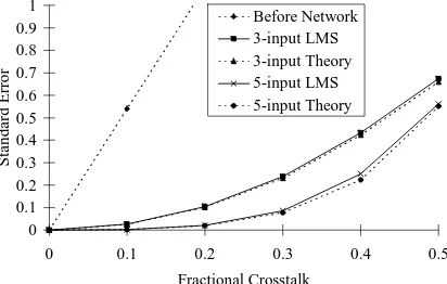
Software was designed to simulate the crosstalk and correction technique using the µ-LMS rule, coded in C. A neuron was trained on 500 sets of random signal samples for each value of fractional crosstalk from 0.0 to 0.5, using a learning rate µ of 0.005. Then, the generalisation performance of the network was measured for a further 500 sets of samples. Curves of standard error for various degrees of fractional crosstalk are shown in Fig 1, for an input range [0,5]. The top trace is the error before the network i.e. if a neural network is not used. This error increases linearly as the amount of crosstalk is increased, as predicted.
[image:2.596.306.512.177.308.2]The middle pair of curves show the error achieved for the 3-input neuron, which is significantly less than that before correction. The ability of the network to reduce the error is best for smaller fractional crosstalk. With ε=0.1 the error reduction is 26.3dB. Comparison with theory shows that the µ-LMS rule is able to achieve nearly the optimum set of weights as obtained from equation 6.
Fig 1. Crosstalk errors after training 3-input and 5-input neurons, compared with theory
The results for a further investigation using a 5-input neuron (lower curves in Fig 1) were found to be even better than those in the 3-input case with an error reduction of 48.6dB for ε=0.1. The improvement is due to removal of the 'error-in-the-error' by the extra weighted inputs. A numerical computation of the minimum showed that the µ-LMS algorithm was again able to achieve nearly the optimum set of weights. Simulations with 7 and 9 input neurons were also carried out and the error was reduced even further. It is noted, however, that the use of a larger number of synapses is likely to increase the amount of random noise in a hardware implementation, and complicates the system by increasing the number of synapses needed. Therefore the 3-input neuron is to be preferred in practice.
2.3. Analogue data with additional random noise We now consider the case where random noise is introduced into each of the transmitters such that we replace xi by (xi + ni), where ni is a sample of gaussian noise added to transmitted sample xi. We can now investigate the combined effects of crosstalk and noise. It is useful to define a Signal-to-Noise Power Ratio (SNR) at the output which includes the crosstalk as a type of noise. Thus,
SNR(dB)out = 20 log (V(rms)signal/ V(rms)noise) (8)
Although the noise in each transmitter is independent, the output from the 3-input neural network is a weighted sum from 3 different receivers, so some of the random noise will be correlated at the output. However, the amount of correlation will depend on the values of the weights. For small amounts of crosstalk requiring small weights w-1 and w+1 and a value of w0≈1, the amount of correlated noise will be small and the output SNR will be similar to that of the noiseless case. With
SE
Ns xs zs N
= −
=
∑
1
0 0
2
1
( )
0 0.1 0.2 0.3 0.4 0.5 0.6 0.7 0.8 0.9 1
0 0.1 0.2 0.3 0.4 0.5
Fractional Crosstalk
St
an
d
ard
E
rro
r
an input signal of peak amplitude 5v and a root-mean-square (RMS) value of Vinputnoise = 0.01v, the input SNR is 51.0dB, corresponding to 0.94 bits of error in a signal coded using 8 bits, which is a reasonable resolution for an analogue signal. Results were generated in the same way as before, this time using 5000 samples of signal plus noise. As seen in Table 1 the crosstalk dominates such that the output SNR is virtually unchanged for all but the smallest fractional crosstalk values, where random noise dominates.
Fractional Crosstalk
SNR(dB)out
Vinputnoise= 0v
SNR(dB)out
Vinputnoise=0.01v
0.0 - 51.0
0.1 43.1 42.5
0.2 31.0 31.0
0.3 23.8 23.8
0.4 18.5 18.5
[image:3.596.81.278.200.343.2]0.5 14.6 14.6
Table 1. Signal-to-noise ratios for crosstalk only, and crosstalk plus gaussian noise (RMS 0.01v)
Vinputnoise
/Volts
0.1
0.2 0.3 0.4 0.5
SNR(dB)in
/dB
31.0 24.9 21.4 18.9 17.0
Fractional Crosstalk
SNR(dB)out /dB (for
the above input noise values)
0.0 31.0 25.1 21.6 19.2 17.4
0.1 30.5 24.7 21.3 19.0 17.2
0.2 27.4 23.1 20.1 18.0 16.4
0.3 22.6 20.3 18.1 16.4 15.1
0.4 18.1 16.9 15.6 14.5 13.6
0.5 14.5 14.0 13.3 12.7 12.1 Table 2. Signal-to-noise ratios for larger amounts of
input noise (RMS 0.1-0.5v)
The next set of results, shown in Table 2, illustrates the effect of larger amounts of random noise (larger than would normally be encountered in an analogue system). It is seen that the larger amounts of random noise account for a significant lowering of SNR at the output for ε between 0.0 and 0.2, and a moderate reduction in SNR for ε=0.3, whereas the loss due to random noise is at most 4.5dB for ε=0.4 and higher. It was also noted that the absolute values of the weights were decreased as Vinputnoise was increased, for any fixed value of fractional crosstalk.
2.4. Binary data
[image:3.596.76.282.382.588.2]algorithm for MLP neural networks is described in the literature[6].
0 0.2 0.4 0.6 0.8 1 1.2 1.4 1.6 1.8 2
0 0.1 0.2 0.3 0.4 0.5
Fractional Crosstalk
S
tandard Error
Before network
3-1 linear/no bias
3-1 linear/with bias
3-1 sigmoid/with bias
[image:4.596.88.287.103.242.2]3-3-1 MLP
Fig 2. Separation of binary signals using various supervised neural networks
All networks tested were found to reduce the error compared with the situation where no network was used (straight line in Fig 2). Increasing the number of training epochs (30000) improved convergence in the 3-input limited connectivity case compared to the previous simulation with only 500 epochs, which shows that convergence is achieved more slowly than with analogue data with the same learning rate. Addition of a bias gave a small improvement in the case of the linear network, although this requires ≈4M weights compared to ≈3M without the bias. For fractional crosstalk up to 0.2, both linear networks have a slightly lower error than the non-linear ones. However, a combination of bias and sigmoidal function reduces the error considerably using a limited connectivity network with ≈4M weights. The best overall error reduction was obtained for the 3-3-1 multilayer network, where errors were small for all values of crosstalk. However, the number of weights required for the multilayer network is ≈16M. In practice, for a hardware system, neither a multilayer nor a fully connected network are likely to be feasible, and after hard-limiting, the limited connectivity network has as good a performance as either of these for fractional crosstalk up to 0.4.
2.5. Binary data with additional random noise A system with binary data is inherently more tolerant to noise since it is acting as a classifier. We considered On/Off keying of sinusoidal signals of amplitude V=5v, with Vinputnoise ranging from 0.0v to 0.5v. The neural network used was the best previously considered single layer limited connectivity network, using a three input neuron with bias weight (i.e. 4 weights per neuron) and sigmoidal output. The output was then thresholded to binary values. At the output, the Bit Error Rate (BER) was computed based on 30000 samples, as defined by BER = Number of errors/30000, using a decision threshold of z0 = 2.5v.
BER was found to be zero for ε≤0.2 for all noise values considered. With ε=0.3, BER was zero for
Vinputnoise≤0.3v, 0.0001 at 0.4v and 0.0006 at 0.5v. With
ε=0.4, BER was zero for Vinputnoise≤0.2v, 0.002 at 0.3v, 0.004 at 0.4v and 0.01 at 0.5v. The cases with ε≥0.5
were not resolvable even in the noiseless case with a BER>0.03 for all noise values, since the neural network cannot define suitable decision boundaries. As crosstalk is increased, the position of the decision boundaries becomes more critical so that a decision is more greatly affected by the random noise. Of course, the situation may be improved by suitable coding and error correction techniques.
3. CONCLUSIONS
We have used limited connectivity architectures for crosstalk removal, such that the number of weights scales linearly with the number of signals. Each sub-channel has its own neuron which can be trained independently of the others. Thus a modular hardware implementation of the network could include separate learning hardware and weight storage for each neuron. Whilst a simple three weight neuron with a linear transfer function was adequate for error reduction with analogue signals, it is seen that an extra weight was required for biasing the transfer function in the binary case, and a sigmoidal output was also necessary to train the network with the Delta Rule. For binary data it is desirable to use hard-limiting outputs after the weights have been trained. The need to accommodate both types of signal suggests the use of a 3-input neuron with bias and a variable transfer function, which can be either linear, sigmoidal or hard-limiting. All these types of transfer function can be implemented using a variable gain sigmoid function F(x)=1/(1+e-kx), which has an almost linear response for small k and an almost hard-limiting response for large k.
ACKNOWLEDGEMENT
The funding for this work was provided by the UK Engineering and Physical Sciences Research Council, grant GR/J16701.
REFERENCES
[1] CRAVEN M.P., CURTIS K.M. and HAYES-GILL B.R. :"Consideration of multiplexing in neural network hardware", IEE Proceedings Part-G, Circuits Devices and Systems, pp237-240, June 1994.
[2] VAN ETTEN W. :"An optimum linear receiver for multiple channel digital transmission systems", IEEE Trans. Communications, pp828-834, August 1975. [3] WIDROW B. and LEHR M.A. : "30 years of adaptive neural networks: Perceptron, Madaline, and Backpropagation", Proc. IEEE, 78,(9), pp1415-1442, September 1990.