Dynamics of a levitated microparticle in vacuum
trapped by a perfect vortex beam: three dimensional
motion around a complex optical potential
Y
OSHIHIKOA
RITA1,2*, M
INGZHOUC
HEN1, E
WANM. W
RIGHT1,3,
ANDK
ISHAND
HOLAKIA1,2,3*1SUPA, School of Physics and Astronomy, University of St Andrews, St Andrews, Fife, KY16 9SS, United Kingdom
2Molecular Chirality Research Centre, Graduate School of Advanced Integration Science, Chiba University, 1-33 Yayoi, Inage, Chiba 263-0022, Japan 3College of Optical Sciences, The University of Arizona, 1630 East University Boulevard, Tuscon, Arizona 85721-0094, USA.
*Corresponding author: [email protected] or [email protected]
Compiled March 29, 2017
We trap a single silica microparticle in a complex three dimensional optical potential with orbital angular momentum in vacuum. The potential is formed by the generation of a “perfect vortex” in vacuum which, upon propagation, evolves to a Bessel light field. The optical gradient and scattering forces interplay with the inertial and gravitational forces acting on the trapped particle, to produce a rich variety of orbital motions with respect to the propagation axis. As a result the particle undergoes a complex trajectory, part of which is rotational motion in the plane of the “perfect vortex”. As the particle explores the whole three dimensional volume and is not solely restricted to one anchor point, we are able to determine the three dimensional optical potentialin situby tracking the particle. This represents the first demonstration of trapping a microparticle within a complex three dimensional optical potential in vacuum. This may open up new perspectives in levitated optomechanics with particle dynamics on complex trajectories. © 2017 Optical Society of America
OCIS codes: (140.7010) Laser trapping; (350.4855) Optical tweezers or optical manipulation; (260.6042) Singular optics.
http://dx.doi.org/10.1364/ol.XX.XXXXXX
1. INTRODUCTION
Levitated optomechanics offers a range of new opportunities and insights at the classical-quantum limit [1–7]. Importantly the absence of a mechanical tether and minimal dissipation leads to the realisation of high quality factors exceedingQ>1012[8] and has excellent potential for quantum metrology [9]. Whilst the majority of studies have focused on linear optical momen-tum transfer, some recent studies have shown interest in angular momentum transfer to levitated microparticles [10–13], includ-ing the transfer of orbital angular momentum (OAM) [14,15]. In such studies phase gradients due to inclined wavefronts of the field can play a central role. By including both spin and orbital angular momentum of light, levitated optomechanics can be a powerful testbed to explore a particle’s rotational degree of free-dom, complex orbital particle motion and may have relevance to spin-orbit light-matter interactions [16,17].
Vortices are ubiquitous in many areas of physics ranging from optics, fluid dynamics, superconductivity, and quantum gases. In the domain of optics, vortices are identified as singular points encircled with helical phase profiles within a light beam, with a characteristic dependence of exp(±i`φ)on the transverse
angu-lar coordinateφ, which is described by Laguerre–Gaussian (LG) transverse modes [18]. The topological charge or azimuthal in-dex`of the beam denotes the integer multiple of 2πthat the field phase accumulates upon circling the beam centre. This topic has gained prominence due to a diverse range of applications in optical manipulation of microparticles, studies of cold atoms, quantum gases, and quantum information processing. Whilst a Laguerre-Gaussian beam scales in size with azimuthal index|`|, recently we have created a “perfect vortex” beam whose radial intensity profile and radius are both independent of topological charge, which has gained significant interest for optical manipu-lation in liquid [19,20]. It is important to note that such a perfect vortex beam is the Fourier transform of a Bessel function and thus realising an annulus with no spatial variation for differing `values, in the sample plane.
three dimensional optical potentials including OAM, which may open up new possibilities for cavity-optomechanics studies.
In this article, we create a perfect vortex beam, which is the Fourier transform of a Bessel beam. Therefore over the three di-mensional space, one would expect the perfect vortex to evolve on propagation to a Bessel beam. For the first time, we trap microparticles within this complex three dimensional optical potential with OAM in vacuum. We load individual silica mi-croparticles into this field and observe their trajectories. The optical gradient and scattering forces interplay with the inertial and gravitational forces acting on the trapped particle, includ-ing the rotational degrees of freedom. As a result the trapped microparticle exhibits a complex three dimensional motion that includes a periodic orbital motion between the perfect vortex and the Bessel beam. We are able to determine the three dimen-sional optical potential by tracking the particle motionin situ. This represents the first demonstration of trapping mesoscopic particles within a complex three dimensional optical potential in-cluding OAM in vacuum. This approach can open up new forms of optical conveyors in vacuum for atoms [25] and mesoscopic particles [26] and new possibilities for fundamental studies of transport phenomena in complex geometries, using mesoscopic dielectric particles, similar to ongoing work in atomtronics [27].
2. NUMERICAL SIMULATIONS
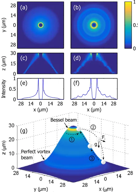
When an axicon is illuminated with a Gaussian beam, a Bessel beam is formed in the near-field, which transforms upon prop-agation to an annulus in the far field. Previously, we created a “perfect vortex” beam, which can vary in azimuthal index inde-pendent of radial scaling and intensity variation, by illuminating a spatial light modulator (SLM) with this annulus and directly imaging the SLM plane onto the trapping (sample) plane [19,20]. In this way the Bessel beam is also formed at the conjugate plane of the pupil of the microscope objective (MO). Using a paraxial approximation of the beam propagation, one can simulate a per-fect vortex starting from the axicon-generated annular beam at the SLM [19]. The beam profiles of such a perfect vortex beam along the propagation direction towards the Bessel beam are also well defined. Figs.1(a, c, e) shows the simulated beam inten-sity profiles of a perfect vortex beam with a topological charge ` = 15, which is used for the particle levitation experiment. The axial view of the beam [Fig.1(a)] is obtained as the sum of the beam profiles at different axial positions of 0≤z≤30 [see Fig1(c)]. It should be noted that the perfect vortex beam is formed atz ≈ 5µm in Fig.1(c), which further propagates towards the concentric annular Bessel beam atz≈30µm, where most of the beam power is available [Fig.1(e)].
[image:2.612.325.549.46.356.2]We experimentally verify the beam propagation after a high numerical aperture MO (Nikon E-Plan,×100, NA=1.25 in oil). The beam profile as a function of axial position (with 1µm reso-lution) is measured using a thin cover glass (Harvard apparatus, 150µm thick), which partially reflects the beam and is imaged on a CCD camera. Figs.1(b, d, f) show the experimentally deter-mined beam profiles, which correspond to the simulated ones in Figs.1(a, c, e). As one can see, the experimental results are in a good agreement with the simulation. Note that the beam profile is dependent on the position of the pupil plane of the MO in the optical system. In practice, it is difficult to position the MO’s pupil exactly at the plane conjugate to the Fourier plane. In numerical simulations, the calculated beam profile is determined by fitting the position of the pupil plane to min-imise the discrepancy between the simulated and experimental
Fig. 1.Spatial profile of a perfect vortex beam propagating along thezaxis with` = 15 compared with numerical sim-ulations. Axial view of (a) a simulated beam, and (b) mea-sured beam, with side view (cross section aty =0µm) of (c) a simulated beam, and (d) measured profile. (e) Simulated beam intensity profile aty=0µm, and (f) measured one. (g) Topography of the measured beam around thezaxis with a schematic of the particle motion where the arrows with broken lines indicate the paths of the particle and the arrows withFi andgdenotes the inertial and gravitational forces acting on the particle. Colour bar indicates the relative beam intensity and applies to all panels. The dataset can be accessed at [28].
beam profiles. Our model indicates that the pupil plane of the MO is shifted by one focal length (0.17 mm for the MO used) away from its nominal position in the experiment. As a result, a cone-shaped annular beam profile is formed as shown both in Figs.1(c, d). Fig.1(g) shows a three dimensional topography of the beam, which is a Gaussian function with a standard de-viation ofσ=17.7µm fitted with the measured cross-sectional beam profile of Fig.1(d). The lateral beam profile [Fig.1b] is pro-jected onto this fitted Gaussian function, where colour indicates the relative intensity of the beam. Here we include a schematic of the particle motion, that depicts its trajectory: i) Trapped and set into rotation at the Bessel beam; ii) Horizontally launched into free space and lands on the perfect vortex beam; iii) Driven by both the scattering and gradient forces towards the Bessel beam.
3. EXPERIMENTAL SETUP
(15.8 mm×12 mm) of a spatial light modulator (SLM, Hama-matsu LCOS-SLM X10468-03). The SLM plane is directly imaged onto the trapping plane with a series of lenses and the MO. The modulated first diffraction order is selected by a pinhole located at a Fourier plane and directed to the vacuum chamber for trapping a microparticle.
The topological charge of the beam is controlled by the vortex phase and a grating phase applied on the SLM. The achievable topological charge is mainly constrained by the back aperture of the MO due to the ring illumination used. In our system, we can realise topological charges ranging from−35≤`≤35 without beam degradation. As most of the optical aberrations in the system are attributable to the flatness of SLM surface, they are corrected effectively by applying a well-known wavefront correction method [29]. We note, however, that the beam profile is also subject to aberrations arising from the refractive index mismatch between the optical system and the vacuum enclosure. The protocol for microparticle levitation is described else-where [11]. Our samples are comprised of dry silica micro-spheres, each of 5µm in diameter (Thermo Scientific, CD9005). We levitate a single microsphere with a linearly polarised perfect vortex beam (`= 15) in air. The optical power is maintained at 81.6 mW, which is measured at the back aperture of the MO throughout the measurements. Once a single microparticle is trapped at atmospheric pressure, the chamber pressure is gradu-ally reduced to 10 mBar.
To investigate the dynamics of a trapped microparticle within a perfect vortex beam in vacuum, we employ a fast CMOS cam-era (Mikrotron, EoSens, MC1362) synchronised with pulses from a nanosecond laser (Elforlight, SPOT: wavelength of 532 nm, pulse width of<1 ns), which acts as a stroboscope at a frame rate of 465 fps [11]. We also employ a fast photodiode (Thor-labs, DET10C, InGaAs) to monitor the transmitted light through the trapped particle via a condenser lens (Nikon, E-plan×10, NA=0.25 in air) to record the particle dynamics.
4. RESULTS AND DISCUSSION
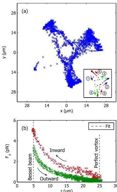
Fig.2(a) shows the trajectories of a trapped microparticle, where the blue cross markers represents the centre-of-mass (COM) of the particle at each frame (see also supplementary video 1, rendered at 25 fps from 465 fps). It is to be noted that the camera imaging plane is adjusted to the perfect vortex beam (z=0µm). Change in the sharpness of the particle boundary in the images suggests its axial motion along the beamzaxis.
[image:3.612.349.537.41.350.2]To understand its complex orbital cycle, we separate the par-ticle motion into inward and outward phases. In the initial state, the microparticle is trapped at the Bessel annular beam (z=30µm) which has the maximum beam intensity in the field. OAM with a topological charge` = 15 is encoded onto both the Bessel and the perfect vortex beams by the SLM, which is transferred to the microparticle via light scattering and sets the microparticle into rotation. Depending on the topological charge of the beam and the orbital rate and the orbital radius of the particle, the inertial force (centrifugal in this case) increases the orbital radial position with respect to the radial trap. However, the particle only remains trapped while the orbital frequency is lower than the trap frequency, i.e. once the inertial force exceeds the radial trapping force, the particle is horizontally launched into free space (outward phase) and falls due to gravity, until the force due to the perfect vortex beam (r=25µm;z=0µm) provides sufficient levitation. Due to both the scattering and gradient forces acting on the particle, it is guided along the beam
Fig. 2.Particle trajectories and force fields around the trap. (a) COM of a microparticle trapped by a perfect vortex beam with `= 15 at a pressure of 55 mBar. Inset shows the path of the particle through one complete cycle. The execution order is indicated by the circled numbers. (b) Stokes drag force deter-mined by a microparticle moving around the trap. The radial range (R≈20µm) in the outward phase depends on the iner-tial force caused by the orbital motion at the Bessel beam (at r =5µm) while the inward phase is driven by the scattering and the gradient forces.
surface towards the annular Bessel beam (inward phase), where the particle restarts its orbital cycle, but its excursion can be on a different azimuthal direction (or branch), as shown in Fig.2(a). It should be noted that, given the cylindrical symmetry of the beam, the particle trajectory are deterministic if all the variables in the system are free from random variations. Practically, how-ever, the particle motion is subject to influence of perturbations in the optical potential due to aberration present in the beam. We note also that multiple microparticles can be simultaneously loaded into this complex three dimensional optical field if de-sired. These particles are stably trapped and continue their orbital motion for a duration of several hours.
in dealing with viscosity in low vacuum, as it does not scale with the residual gas pressure but significantly depends on the ratio between the particle radiusrsand the mean-free-path ¯`of the surrounding gas molecules [11]. Here we experimentally determine the viscosityµ(P)in the vicinity of the microparticle by taking the ratio of the rotation rates of a spinning birefrin-gent microparticle –vateriteof the same size between pressures ofP(under consideration) andP0(atmospheric pressure as a reference). In this way, the local viscosity is determined to be µ(P) =µ0Ω(P0)/Ω(P)whereΩdenotes rotation rates andµ0 the gas viscosity of air.
Once the local force field has been probed by the single mi-croparticle moving around the optical potential, we can establish the 1D map of the Stokes drag force depending on the radial po-sition of the beam. Fig.2(b) shows such a force field depending on the radial position of the microparticle. It is worth noting that the outward and the inward phases of the particle motion are dis-tinguishable. Green crosses are for the particle launched horizon-tally away from the Bessel annular beam, while the red crosses are for the particle optically driven towards the top Bessel beam. We note that the microparticle is set into rotation at the Bessel beam until it gains the inertial force to overcome the trapping potential and is launched for another orbital cycle. We measure the initial velocity of the horizontal launch to be in the range of v0=8.2±0.7 mms−1(2σ)with its launch height ofh=30µm. In the absence of frictional drag, we estimate the radial range that the microparticle can reach to beR=v0
p
2h/g≈20µm wheregis the acceleration due to gravity. This is in a good agreement with the experimental result in Fig.2(a, b).
The optical potential for the microparticle can be determined from the radial dependence ofFs(r0)as
U(r0) =−
Z r2
r1
Fs(r0)dr0. (1)
The integration of the fitted curve (broken line in Fig.2(b)) to the measuredFs(r)(red crosses) in the range fromr1=25µm tor2 =5µm yields a change in the optical potential from the perfect vortex annular beam (z=30µm) to the Bessel annular beam (z=0µm). Fig.3(a) shows the experimentally determined optical potential (blue solid line) dependent on the particle radial position.
For dielectric particles, the optical potential of the gradi-ent force is linearly related to the optical field intensity as U(r) = α|E(r)|2/2, whereαis the particle polarisability. The potential curve (blue solid line) is further fitted with the beam intensity profile averaged over the particle diameter of 5µm (green dotted line) using a nonlinear least square fitting method (lsqnonlin) available in MATLAB. Here we found a good agree-ment between the two curves with a residual error<5%. As such the optical potential curve is calibrated with the microparti-cle moving around the complex potential and yielded the deep-est potential well of−3.8×10⁻¹⁸J at the annular Bessel beam. Fig.3(b) shows the three dimensional optical potential profile of the perfect vortex assuming the cylindrical symmetry of the beam.
[image:4.612.345.536.44.248.2] [image:4.612.344.535.495.678.2]It is intriguing to understand the dynamics of microparticles trapped with a different topological charge. Fig.4shows the particle trajectories at`=3, 10, 30 corresponding to blue, green and red crosses, respectively. The radial range that the micropar-ticle explores depends on the inertial forceFi=mv20/r, i.e. the particle launch velocityv0, which is determined by the charge `and the radial trap stiffness or frequency. It should be noted while the annular size of the perfect vortex beam (atz=0µm)
Fig. 3.Optical potential profile of the trap. (a) Experimentally determined optical potential (blue solid line) probed by a mi-croparticle moving around the beam axis (r = 0µm). This potential curve is fitted with the beam intensity profile aver-aged over the particle diameter of 5µm (green dotted line). (b) Optical potential presented in 3D. The dataset can be accessed at [28].
remains unchanged, the Bessel beam (atz=30µm) scales with
|`|. Here, we observe increasing orbital speeds with larger` until the outward inertial force exceeds the radial trapping force in the system, when again the particle would leave its azimuthal trajectory. A special case arises when the annular Bessel beam is comparable to or smaller than the microparticle e.g. when `=3, which results in the microparticle rotating at a fixed trap-ping position at the Bessel beam (blue crosses). This suggests a fundamental limit to the OAM that may be transferred to a trapped, orbiting particle, dependent upon the beam parameters and inertial forces present [14].
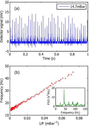
The motion and trajectory of microparticles is also dependent on the residual gas damping coefficientΓ. Fig.5(a) shows the characteristic intensity variation of the photodiode signal at a residual gas pressure of 14.7 mBar. Since the beam power is concentrated at the annular Bessel beam, the change in light intensity is only appreciable when the particle scatters that part of the beam. Fig.5(b) shows a power spectrum of the photodi-ode signal (inset) at 14.7 mBar and the frequency of this orbital cycle depending on the residual gas pressure. It is worth noting that the frequency f scales inversely with the gas pressureP. For sufficiently low pressure that the mean free path ¯`of the background gas is larger than the particle radiusrs, it is known that associated viscosity experienced by the particle moving through the gas scales asµ∝rs/¯`∝P[11]. One expects that the frequency varies asf ∝1/µ∝1/P, as shown in Fig.5(b).
Fig. 5.Particle oscillation frequency at different gas pressures. (a) Photodiode signal of the forward scattered light from a trapped microparticle. (b) Oscillation frequency of a trapped microparticle inversely dependent on the background gas pressureP. Inset shows a power spectrum at the residual gas pressure of 15 mBar showing the oscillation frequency of 45 Hz. The dataset can be accessed at [28].
We observe that asΓdecreases with lower pressure, the parti-cle velocity increases in a wider orbital trajectory, but completes the orbital cycle faster, until the radial range exceeds the light field. At this gas pressure, the particle would leave its trajectory.
5. CONCLUSIONS
In summary, we have explored particle dynamics in a three dimensional potential in vacuum. Our potential comprises a perfect vortex beam, which is the Fourier transform of a Bessel beam, in vacuum. The perfect vortex evolves on propagation to a Bessel beam within tens of micrometers with a high numerical aperture MO. We load an individual silica microparticle into this complex three dimensional optical potential possessing OAM
and observe its trajectory. In the underdamped case, the particle inertia plays an important role in its dynamics, where the optical gradient and scattering forces interplay with the inertial and gravitational forces acting on the trapped particle. As a result the trapped microparticle exhibits a complex three dimensional motion that includes a periodic orbital motion between the per-fect vortex and the Bessel beam. As the particle explores the whole three dimensional volume not solely restricted to one anchor point, we are able to determine the three dimensional optical potentialin situby tracking the particle. This represents the first demonstration of trapping mesoscopic particles within a complex three dimensional optical potential in vacuum. This approach can open up new possibilities for fundamental studies in levitated optomechanics. Particular studies may include the controlled particle transport into and out of a cavity based on the approaches of optical conveyors for atoms [25] and mesoscopic particles [26], and collective motion of multiple particles [27] and optical binding [30].
FUNDING INFORMATION
The authors acknowledge funding from the UK Engineer-ing and Physical Sciences Research Council (EPSRC) Grants EP/J01771X/1 and EP/M000869/1. We thank Professor Takashige Omatsu, Chiba University, and Dr Graham D. Bruce, University of St Andrews, for useful discussions.
REFERENCES
1. A. Ashkin and J. M. Dziedzic, “Optical levitation by radiation pressure,” Appl. Phys. Lett.19, 283 (1971).
2. T. Li, S. Kheifets, D. Medellin, and M. G. Raizen, “Measurement of the instantaneous velocity of a brownian particle,” Science328, 1673 (2010).
3. T. Li, S. Kheifets, and M. G. Raizen, “Millikelvin cooling of an optically trapped microsphere in vacuum,” Nat. Phys.7, 527 (2011).
4. P. F. Barker, “Doppler cooling a microsphere,” Phys. Rev. Lett.105, 073002 (2010).
5. D. E. Chang, C. A. Regal, S. B. Papp, D. J. Wilson, J. Ye, O. Painter, H. J. Kimble, and P. Zoller, “Cavity opto-mechanics using an optically levitated nanosphere,” P. Natl. Acad. Sci. USA107, 1005 (2010). 6. J. Gieseler, B. Deutsch, R. Quidant, and L. Novotny, “Subkelvin
para-metric feedback cooling of a laser-trapped nanoparticle,” Phys. Rev. Lett.109, 103603 (2012).
7. L. P. Neukirch, E. von Haartman, J. M. Rosenholm, and A. N. Vami-vakas, “Multi-dimensional single-spin nano-optomechanics with a levi-tated nanodiamond,” Nat. Photonics9, 653 (2015).
8. J. Gieseler, L. Novotny, and R. Quidant, “Thermal nonlinearities in a nanomechanical oscillator,” Nat. Phys.9, 806 (2013).
9. A. A. Geraci, S. B. Papp, and J. Kitching, “Short-range force detection using optically cooled levitated microspheres,” Phys. Rev. Lett.105, 101101 (2010).
10. Y. Arita, A. W. McKinley, M. Mazilu, H. Rubinsztein-Dunlop, and K. Dho-lakia, “Picoliter rheology of gaseous media using a rotating optically trapped birefringent microparticle,” Anal. Chem.83, 8855 (2011). 11. Y. Arita, M. Mazilu, and K. Dholakia, “Laser-induced rotation and
cool-ing of a trapped microgyroscope in vacuum,” Nat. Commun.4, 2374 (2013).
12. Y. Arita, M. Mazilu, T. Vettenburg, E. M. Wright, and K. Dholakia, “Rotation of two trapped microparticles in vacuum: observation of optically mediated parametric resonances,” Opt. Lett.40, 4751 (2015). 13. S. Kuhn, P. Asenbaum, A. Kosloff, M. Sclafani, B. A. Stickler, S. Nimm-richter, K. Hornberger, O. Cheshnovsky, F. Patolsky, and M. Arndt, “Cavity-assisted manipulation of freely rotating silicon nanorods in high vacuum,” Nano Lett.15, 5604 (2015).
K. Dholakia, “Orbital-angular-momentum transfer to optically levitated microparticles in vacuum,” Phys. Rev. A94, 053821 (2016). 15. L.-M. Zhou, K.-W. Xiao, J. Chen, and N. Zhao, “Optical levitation of
nanodiamonds by doughnut beams in vacuum,” Laser Photon. Rev.11, 1600284 (2017).
16. K. Y. Bliokh and Y. P. Bliokh, “Conservation of angular momentum, transverse shift, and spin hall effect in reflection and refraction of an electromagnetic wave packet,” Phys. Rev. Lett.96, 073903 (2006). 17. O. Hosten and P. Kwiat, “Observation of the spin hall effect of light via
weak measurements,” Science319, 787 (2008).
18. L. Allen, M. W. Beijersbergen, R. J. C. Spreeuw, and J. P. Woerdman, “Orbital angular momentum of light and the transformation of laguerre-gaussian laser modes,” Phys. Rev. A45, 8185 (1992).
19. M. Chen, M. Mazilu, Y. Arita, E. M. Wright, and K. Dholakia, “Dynamics of microparticles trapped in a perfect vortex beam,” Opt. Lett.38, 4919 (2013).
20. M. Chen, M. Mazilu, Y. Arita, E. M. Wright, and K. Dholakia, “Creating and probing of a perfect vortex in situ with an optically trapped particle,” Opt. Rev.22, 162 (2015).
21. J. A. Rodrigo, T. Alieva, E. Abramochkin, and I. Castro, “Shaping of light beams along curves in three dimensions,” Opt Express21, 20544 (2013).
22. J. A. Rodrigo and T. Alieva, “Freestyle 3d laser traps: tools for studying light-driven particle dynamics and beyond,” Optica2, 812 (2015). 23. S.-H. Lee, Y. Roichman, and D. G. Grier, “Optical solenoid beams,” Opt.
Express18, 6988 (2010).
24. E. R. Shanblatt and D. G. Grier, “Extended and knotted optical traps in three dimensions,” Opt. Express19, 5833 (2011).
25. S. Schmid, G. Thalhammer, K. Winkler, F. Lang, and J. H. Denschlag, “Long distance transport of ultracold atoms using a 1d optical lattice,” New. J. Phys.8, 159 (2006).
26. T. ˇCižmár, V. Garcés-Chávez, K. Dholakia, and P. Zemánek, “Optical conveyor belt for delivery of submicron objects,” Appl. Phys. Lett.86, 174101 (2005).
27. C. Ryu and M. G. Boshier, “Integrated coherent matter wave circuits,” New. J. Phys.17, 092002 (2015).
28. Y. Arita, M. Chen, E. M. Wright, and K. Dholakia, “Data underpinning: Dynamics of a levitated microparticle in vacuum trapped by a perfect vortex beam: three dimensional motion around a complex optical poten-tial,” University of St Andrews, http://dx.doi.org/10.17630/7ad8b998-a344-4158-bfb2-e7c66f82377c(2017).
29. T. ˇCižmár, M. Mazilu, and K. Dholakia, “In situ wavefront correction and its application to micromanipulation,” Nat. Photon.4, 388 (2010). 30. K. Dholakia and P. Zemánek, “Colloquium: Gripped by light: Optical