TRANSIENTS IN ANTENNAS
A thesis pres ed for the degree of
Doctor of Philosophy Ele cal Engineering the University of Canterbury,
stchurch, Ze ffild.
by
G.A. Burrell, B.E.(Hons.)
exciting it may be called an antenna. It is ic grounds that such a pile of tin does not good antenna, and i t is worthwhile to search
characteristics that can be used to
a some dis
ate between an ordinary pile of tin and one that s a od
on
anterma. When the properties of a good enna are consider-ed, the only one that stands out is g
metal.
A
good antenna does not have an ens ears, flaps, and springs that play no us business of radiating.C.G.
R.H.
economy of e of met lic
Measurement and computational procedures are developed for inferring the frequency responses (both driving point and field) of an antenna or antenna system from measure-ments made in the time domain (using nanosecond
time-domain-reflectometer techniques). A hybrid computer has been us to present simUltaneous displays the pulse response and the frequency response (in both magnitude and phase). The experimental te~hnique used to empirically design a new wideband antennu for the
3-30
MHz band from measurements made on sc e models.which is to faithfully
A
design principle for.an antenna effi ently t t a very wide bruldwidth signal is also esented, and an experimenta) evaluation of a pr iminary design is reported.T frequency responses of dual parts of an antenna can be isolated and splayed simply th this experimental teChnique. To illustrate this, input imp ance and radiation from an effectively inite monopole are
esented. These results verify pr ous theories. Trans-ssion and r lection coefficients describing the propagat-ion of m0:20ChroLlstic current waves on thin bent wire
ante~nas are inf from p s of the lected pulse
I am greatly indebted to supervisor Mr R.H.T. Bates for his encouragement and guidance over t duration of this project.
I so espe ally thank my wife Katharine for her patience and encouragement.
Mr E.J. Young of the New Zealand Post Office is thanked for his support arranging t construction of the
antennas developed this t sis. I so thank the drawing ice staff of the Post Office for their diligence in pre-paring most the diagrams in this the s.
The fi~anc as stance of New Zealand Po Office
Abstract
Acknowledgements T Ie of contents
ssary e
CONTENTS
i
vii xi
1: Review of transient re onse of antennas 1
C
I. MEASUREMEIJlr TECHNIQUES
2: Inf frequency re onses from ru1tenna measurements made in domain
-time-to quency transf ion (TFT) tecbni
2.1
Introduction2.2
The pulse re onses of an antenna system2.3
TFT tec2.3.1
Measuring a from a sampl2.3.2
Using2.3.3
Errorsa In
d computer on~
calculated spe
2.3.3 1
Errors in calculatof a si
2.3.3.1.1
Aliasing2.3.3.1.2
Truncation2.3.3.1.3
Timing2.3.3.2
ise-like errors2.3.3.2,1
Amplifier noise2.3.3.2.2
Timing jitter2,3.3.2.3
Quantisationits time sa
oscilloscope
the spectrum values
11
11
11+
18
25
25
30
30
33
34
transmission lines 2.3.4 Measurement resolution
2.3.5 A practical evaluation of error in an inferred reflection coefficient
37
38
2.3.6 3-point scanning using a hybrid computer 40 2.4 The far Id transfer functions of an enna2.5 erring transmission and r lection
coefficients for bends in wire ennas from a part of the r lec pulse response
CHAPTER 3: Measurement systems and experimental procedures
3.1 Introduction
3.2 The driving point measurement range
3.2.1 Exper~mental procedure for me reflection coef cients
3.2.1.1 Measuring the test pulse 3.2.1.2 Measuring pulse response
3.3 Apparatus for measuBing the characteri cs bends wire antennas
3.3 1 Experimental ce efor measuring b 3.4 The far field measurement range
3.4.1 Calibrating the standard antenna
3,4.2 Experimental procedure for measur far field transfer functions
3.4.2.1 Nle the test pulse 3.4.2.2 asuring the pulse response 3.4.3 cking the measurem accuracy 3.5 C ibr ing the s ling os lloscope
44
53
57
57
59 60
65
CHAPTER 4: Generating high spe signals
4.1
Introduction4.2
Avalanche mode switchingi i i
f§b~
78
78
81
4.3
Construction of avalanche stor pulsegenerators
4.3.1
Relaxation oscillators4.3.2
A trigger pulse generator4.4 Pulse forming
4.4.1
Differenti ion4.4.2
StubsPART DRIVING POINT RESPONSES
CHAPTli;R
5:
Res'ponse narrow band antennas5.1
Introduction5.2
oretical considera~ions5.3
Experimental det ion ofof an effectively inite monopole
5.4
SCUSSloninfinite
5·4.1
5.4.2
ent response of dipole CfillPTER 6: Response of6.1 lon
6.2 ical consi
6.2.1 C c monopoles
6.2.2
Fan monopoles6.3
Measured responsesc mO:i.l.opoles e-corrected c
antennas
iOEs
monopoles
impedance
83
83
86 86 86 86
93
96
1
107 109 109 113
115
115
6.4"
Discussion6.4.1 Conical monopoles 6.4.2 Fan monopoles
6.4.2.1 Reflected pulse re 6.4.2.1.1 Sheet metal fans 6.4.2.1.2 Wire fans
6.4.2.2 Frequency responses 6.4.2.2.1 Sheet metal fans 6.4.2.2.2 Wire fans
es
6.5 A estion for further work
C
7:
wideband Wlre antennas for7
,1• I duction
asymmetrical trilliigular 7.2.1 Sc e model measurements
7·3 7.3.1 7.3.2
An
7.4 r
asymmetrical triangular fan son of measured input
scale model monopole square f~n
1 measurements square fan lopments
s
121 121 123 123
1
1
125 125 127 128 140 140 144 144 147
PART III. FAR FIELD RESPONSES
CHAPTER 8: faithful transmission width signals
Introduction
very wide
band-General theoretical considerations 8.1
8.2
8.3 A design principle for a system
hful transmission
8.4 Suitable types of antenna CHAPTER
9:
Measured Responses9.1 Introduction
Radiation from base and tip of monopole C cal monopoles
9.4 Phase-corrected c
9.5
Fan monopolesDiscussion
cal monopoles
far fie responses CRA.PTER 10:
10.1 Radi 10.2 Fai
lon a monopole
transmission of wideband s
PART IV. PROPAGATION OF C~RENT ON BENT At'\lTENNAS CHAPTER 11: Propagation of current on b
antennas 11.1 Introduction 11,2 The driving po
ennas
11.2.1 lect from 11,2 2 Reflections fro~
11.2.3 Transmission 11,3 Transmiss and
bent antennas
pulse responses of wire
b
b
b wires
lection coefficients for
11 3.1 Comput frequency responses 11.3.1.1 Transmis on coeffici s
11 3.1.2 11 3.2 11.3.3
Refl coeffici Computed responses Discussion of errors
s
11.4 Discussion of the responses for further work
APPENDIX 1:
A1.1 A1.2 T
The organi lon of a program for simultaneous domain pulse responses of antennas
analogue computer
di~ital computer
APPENDIX 2: The organis on of an on~l
suggestions
d computer ay of time quency re
hybrid
computer for 3-point scan sampling A2.1 T the scan s e
A2.2 analogue computer
225 225 228 228 229 233 es
A2.3 The al computer 267
'cape format A2.4
A2.5 Card format for IBM 360/L~4 proces A2.6 The
A2.7 Subse APPENDIX 3: C
1
fectiveness of int scanning
wave
improvement to the program ation of T(f) and R(f) for a
O.
monopole at f es when er·-wavel and threem is a
er-L1. : 2rs for
~easure-268 268 269 270 275 ments long of S8.111P
orted in I-III 278
vii
GLOSSARY
Symbols, and definitions. ss
other-Wlse defined symbols the meanings g
a radius conductor of co
of antenna
ADC analo to digital converter
b radius outer conductor of co
c veloc of electromagnetic waves
c. w. c wave
DAC to analogue converter
dB dec el
DFT dis Fourier transform dia.
E(f) eqn.
f
FT FFT
diameter
ec c field intensity as e
F
f
gen
lon quency
er transform
Fourier transform
function of t ( )
low:
1 radius
ee space
ion of frequency
get)
G(f) of get); gain of enna as function of fre
o
GHz gigahertz (107 Hz)
H etic field int vector
H(f) tem transfer function of an antelllla as of frequency (section 2.3)
(f) ective height of an enna as flmction of equency
Hz
j K
k
L
m
MHz ms mv
n
N
ns
.2
J z
surface current density vector radian wave number ~ 2n1~ length of antenna
metres
megahertz (106 Hz)
millisecond (10-
3
second) millivolt (10-3
volt) refract indexnumber of samples
nanosecond (10-
9
second)narrow pulse: pulse whose duration 1S short compared. to
pf ps
time it takes to propagate, at light, along an antenna.
picofarad (1 12 farad) cosecond (10-12 second)
velocity of
pulse duration: dur ion of a pulse measured between the points at which its amplitude is -20 dB of its pe am.plitude (section 4.1)
~ulse ris ime: the time t~ken for a pulse to rise between
r
'iO% and of its amplitude
distance separat of curvature
two antenna3 (chapters 1 0); bend (chapter 'i 1)
rad. radius
R(f) reception tr&''lsfer func on of an antenna as fun ion frequency (section 2.4)
snm(t): time domain scattering parameter from port n towards po.rt m
Snm(f): of surn(t)
SWG standard wire gauge
t time
T
T(f).sampling erval
transmission transfer function of an antenna as function of equency (section 2.4)
TDR
time domain reflectometerTEM
TFT
TM
. u(t)U(f)
v
vet) V(f)
VI1F
VSWR wZ
s
transverse ectromagnetic
time to frequency transformation transverse magnetic
test pulse
FT
of u(t)velocity factor ( propagation to c)
ratio the velocity of
response of ell~a or antenna system to u(t)
FT
of v( t)very high equency
voltage standing wave ratio
(1-w) is the frac on of the samples in a time domain record to ch a data window is appli (section 2.3.3.1.2)
SlJ.rge imped.ance (section
5.
if-. 2)Z(f) el1na input imp e as func on frequency
0: loss factor
transmission co ici for b wire eIL"1.a as function of frequency (c er 11)
ref) current reflection coefficient for bend in wire antenna as funct of frequency ( chapter 11)
l)
e
A
Ilv
v
2
(J
w
quantising interval
error; permittivity of free space
relative permittivity
characteri ic impedance of free space (= 120n ohms)
general angle
wavelength
permeability of free space
microvolt (10-6 volt)
amplitude jitter (sec on
2.3.3.2.1)
confidence level (section
2.3.3.2)
voltage reflection coefficient at input of an
antenna as function of frequency (section
2.3)
variance
time delay
half flare angle (chapters 6 and
7)
apex angle (chapter
7)
radian equency := 2 n;f
xi
PREFACE
During t last de a number papers have eared
(mainly IEEE Trans ions on ennas and ation)
in which time response of an antenna to transi
signals is obtained by a er transfo ion of its
frequency re e. In cases exp s were to
substanti e the calculations. These c ations can
be made for ennas for ch the fre response is
known, and effective limited signals.
other with mo equipment, measurements of
transient re e of VHF microwave ennas can be with less 1 than c onal frequency domain
measure-ments. The re an antenna is usually more
useful in radio communications engineering the transi
response. s sis is conc wit~1 the
quency re e (in both and e) of an antenna
from a pair of surements the time The
erimental c is call the quency trans
f on (TFT) technique, ational
,
cedures are loped for obtaining the ency responses
(bo input and far field) of an eIHla or em of
ennas by the technique. practic of the
te clu'li que 1S by its use the empiric design
and oprnent of a wideband enna for the
:3
MHz band measurements on scale Is, and in study ofthe propagation current on antennas. A design pr e for an enna system 1S to l' ly and
The
dent by t
easing importance of
attention be
technique is evi
devoted to i t in the
literature. Rec issues of the j
papers which been of considerable
These papers come two places:
Centre, Mas s, where'the
TFT
te applied to t measurement of coaxialponents (inc cables) and dielectric
(Nicolson
1968,
colson and Ross1970);
Research C where the uti
a sampling oscilloscope a computer for
s contain
to the author.
Rand Research
e has been
ssion line
com-als
network been realised, and s
IBM Watson
union of
general
and
hardware is being
funct~ons (Farber
for a variety of me
1969,
Stuckert1969,
t1970).
As far as the author is aware, this thesis r s t rst application of the
Chapter 1 lS
previous work on the
work relevent to this
of trffilsients into p
t he remainder
s. In the followj
licitly.
I includes
tecrillique and its
Because t s measuring
technicrue to antenna measur s.
oductory, and contains a ew of
response of Only
s is included, e.g. ation
is excluded. New work is
contain-t sis, which is divi d
scussion, the new work is
s and is concerned on to antenna
is essentially new
four
cat
s.
is
work are inc for completeness. er 2 describes how to measure
responses of an reflection co functions of
point (reflected) far field pulse enna system and how to compute the
ent and system transfer function (as ) from them. The far field transfer functions for an enna on transmission reception are introduced and how to er them from a me . using a standard antenna is scribed (the use of a antelma with TFT procedures is new). It is shown a sampling oscilloscope (whi used for a receiver) can be connected to a small general
only a few times the measurement omatically . . A det error is included.
se computer (which are now available co of a sampling os 1 scope) so
t
ti te
h
(1969)
but some TFT technique isslotted l.ine me
sequent process can be done
~)cussion of the sources of
s follows Nicolson
(1968)
~~d ions are made. The ofby comparison The advantages
a COl1ven-t TFT over conventi quency domain methods for antenna measllJ:'emen.ts are pointed out. In
equency responses of be iso ed and displayed
parts of an cru~
the TFT technique. is
des
measur
h07l tr&'l.smission lection coefficients e the propagation and reflec of monochromatic
waves on bent wire only part of
emlas can be inferred from a lected pulse response. This camlot be done simply with fre domain methods.
is ed by the s 1 osc~lloscope ele
overcome this, Nicolson (1969) has devis a hod of s8lIlpling called
and a sampling os
o scanning which uses a small computer lloscope in a control T s measure-ment method, for
described in ments reported
ch Nicolson has a pending, is er 2. It was used for many of the measure-t s thesis. 3-po represents a major advance
experimental te domain measurem
the TFT technique because, with careful que, the accuracy
s can be equalled
sion frequency ssibly exceeded. The s of the measurement
for all t measurements reported in chapter 3. calibration of making far f Id measurements is s
s which was used s thesis is outlined andard antenna
ed, The experimental proce s are given in detail.
Chapter 4 concerned wi ing high speed
signals, this project commenc there were no le pulse gene ors available in New Z and. So, some
be bui Some of the des were so successful (200 co-second setimes were achi d) that con,struction Is are
less
c
(
The total co the cost of
so contains a eed signals.
of the circuit compon al output connector.
ew of methods
s is
driving point re es of antennas are seuted II j which inc s chapters
5-7.
er5
con--with a repres dipole). ~he 1
l respm::.ses
been concerned with
example of a narrow band antenna e contains inve of the
er
5
is review and discus illustrate how thetechnique can be used to frequency response of
erent parts of an antenna, impedance of an
ectively infinite monopole is s This result, which has never been obt ctly from experiment
before, verifies previous t s,
The characteristics of two wideband antennas, the
conic-al monopole and the fan monopole are investigated in chapter
6. The driving point cs of the conical
mono-pole are included because t s antenna type is of interest
in Part III. The chapter 6 is an investigation of some wire fan ennas. constructed from a
contin-uous sheet of metal are to be good wideband antennas
(Brown and 7Joodward,
19
there does not seem to beinformation avai made of discrete wires.
investigation ed identifies the differences
performance between met fans and wire fans.
Chapter
7
cont s from chapter 6 and explores potential of dipoles as wideband ennas t3-30
MHz
quency (HF) band. The New Z stOffice ) a need for a simple ( , e t) HF wideband enna for radio telephone s ces to i ated
parts of New Ze and the Pacific I
discus
R
H.T. Bates (project sor) andE.J.
Young ( ) a arose of using some of vnre fan.
In er
7,
two HF antennas are deve cally byinf impedance of one- ze scale
models h the Tt"I' tecIh"lique. on full
luded. An
sis) is about to Sugge for improving designs are
improved sign (not ed in this t
begin service asses s.
I I I (chapters
of terising an
8-10) is conc with the problem
em which will
reproduce faithful
icient antenna
the output of receiving enna,
a wide bandwidth signal which been applied to the input of the transmi antenna. 8 cannot be
principle bas
e with
on a note
s A des by
antenna
es (967) for e types of
'T'he far fi
chapter
9.
sted by
an antenna is given in chapter 8, and
enna are discussed.
ic
responses of c
is shown t
monopoles are
report-e-correct
oretical approach presented
(as
chap.ter 8)
conical monopoles improves t system re
ication of pr
dependence
e.
is an
predictions
ch occurs
cylindri
Chapter 10
ous
ons of this
inted out.
erimental
the fre
a transi
monopoleo
scusses
is radiated
results pres
ers, and lS concerned
Some errors in the
Part IV (chapter 11) ains an
ous theoret
the radiat
the base of a
ed in the
s.sible exten~
are
.the prop
measur
of current on bent wire
tal study
ennas. Ac
s of the driving point responses of bent wire
e
xvii
pulse reflected a sharp bend is a compressed version of
the incident
gradual bend
length of
(which were
propagation
bent wires are
se and that a pulse
its a continuous
Transmission
ed earlier in
lection of mono
around a
ection from the whole
of the
wires and
mechanism
These re
ions for
All
e
erred from
the pulse refle
ection coeffi
ter 2) describing
ic waves on t
measurements. Insp
from the tip of
erred frequency re es reveals the
current propagation on the bent wire
s 5.::.:'e new. The
this work.
measurements
er concludes with
performed autoID9.tically by
this thesis were
-590
hybrid computer ions
the Ele Engineering The s were
process either by the
EAI-dig computer of the
C With the except
HARM,
which was a fand a measurement program us
used were wri by
ASSEMBLER language
ers published, ac
cs from this thesis are:
computer or by the 360/44
ty of Canterbury er
standard IBM s ic
-Fourier-transform thill,
chapter 11 , 1 er
author in or
or suh~ni tted to e on
( i) R.H.T. Bates and GaAe Burrell: "Simul ous clisplay
ennas II, paper
of frequency se responses of
sented at Conference on
Computat-lon, Nll.mi er
19'70,
ap:.o83T in( )
R.H.T Bates and G.A. Burre IITowards faithful radio transmission of very wide bandwidth signalslt,
paper to appear in IEEE Transactions on Antennas and Propagation.
1
REVIEW OF OF Acl'ifTEl\TNAS
During the last
15
years or so considerable interest has been shown in the transicharacteristics of antennas. trend is to use physically
on and driving point
the use of very short pulse mo
radar systems the ennas. At the same time
signals to improve ant. Also, electronic range resolution has become
scanning has made arrays very rapidly. antenna system to re mitted signals
radar system. can be faithfully system is ultimate point and the si
antenna system.
In the e 1,)60's s
r
eer the beam of antenna it is the inability of the rapid changes in the
overall perform~~ce of bandwidth of the signal which
by a radio communications by both the transient
a~ on char~cteristics of
pulse generators and f oscilloscopes became available so that the i responses ennas which were a reall
could be me This stimulated intere
ze
ent responses becaus oretical predictions co be substant-·
t measure~
iated by ment of of ous usually s can re
pulse
Papers appeared radiation and enna types. The input
(i.e. dc) pulses or
be generated with semiconductor ion, or the step riset e5 was
agation time of ele
re onses were
antenna. Within the st few years interest , and the only research team currently working on enna transient responses, as far as author is aware, is Sperry Rand Research C , Sudbury, Massachusetts the
leadership of It is cus exciting volt time1 , Mathema differentials dependences. arbitrary t solutions are obtained for an deriv8s a f
antenna short
is obt d
Lee (1970) dipole t
s
most antenna problems assume an e (or current) which varies soidally with c solutions are fac l because time
egrals are replaced Ie frequency s cannot be done if signal is an
on, and consequently ect time domain emely difficult. however been
e cylindrical enna. Wu (1961b) for the cur:r:ent on on a dipole by a step function of vo for times
switch on of the vol e, The same result a different way by (1962). Latham
a formula for el of an infinite by a step function of vo age. Similar results earlier been reported by 11 (1960a),
equal TIle two The t
1
c teristics of'antennas can be described with
i in the time
are related by a onse of an antenna
( oretically) be det
ce the monochromatic because most erma monochromatic signals to
the signals are at most a few
ennas
or frequency domain, er transform (FT).
signal can d completely from the
eristics are very lications require e be tra2smitted or rec
ed the bandwidth
3
frequency re e, Conse most retical ent
re es have en obtained by taking inverse FT of the
quency response.
A complete
signal re
erminat of the t response for any
es knowledge of the frequency re e up to the highe frequency for which the signal
icant Obt
ion characteristics
the monochromatic
8.-11 antemla is essent
and
a
boun-em of so Max'vvell t s equations subj ect to
conditions imposed the antenna and the source. This
can be surprisingly difficult. An of the enormous
amount of fo which s been exp d by many people over
decades on a mathematical
enna can be had by thumbing
s of the I
the pages
ar
(1956). Not all antennas have been solved
King
cally,
on
(Jasik e,g. the formulas describing the and
characteri ics of b~lic ant ennas are ernp iri c
1961, chapter '7), Theoretical so ion;], when lable,
are only
theoretic
a restri
values of
range of parameters, e.g. the
input
10' wavel
edance of ectrical
long are given by Wu thin dipoles up to
(1961a). However
radius-to-wavelength
they do not repres
are only for four values of the
o (
over a frequency range.
frequ response high fre
response can only be erred for
input waves.
S (1960) ers the
reception responses a thin
a 3:1
edance
of knowl
). Thus
a fixed antenna
e of the
es means that the t
effective band-limit
ient tr ssion
a step function volt e. The responses were obtained for various source illlpedances. Some his results were sub~
stanti ed by a transmission eriment between two monopoles mounted ove a ground plane. ever, because Schmi
truncated s inverse FT premature his theoretic results are in error. This is discussed later in chapter
10.
Theient transmission reception responses a
cylindrical monopole excited by eband pulses various durations are es d by Schmitt ale
(1966).
Their calculations arQ more accurate than those of Schmitt(1960)
because knowledge of the frequency response was more complete. Good agreement til experiment was obt . They show that for monopoles which are very short compared the wavelength of the highest significant frequency the inputsi the e of the ated f Id is prop or onal to the se time derivative of the input signal When the short monopole is rece the shape of the received gnal is proportional to t time derivat of shape of the incident field. These differences between smis ffi1d reception ee th Mayo et alb
(1961),
who were probably the f st to point out that'the impulse response of an antenna is different on tran ssion aJd ree tion. If a s e int circuit is used for a load? t the short recerecei ver of
monopole is a f thful ( inefficient) ient signals. These results were so confirmed by experiment.
a l a r er? SOD. and W ams
(1965)
the smission ili'1d reception re,s'Ponses of e
5
They show that for very short cones transi behaviour is the same as for thin cylindric antenna cribed
previous paragraph. They so show for a e cone shape the r ed fie is a r ca of the put pulse until such time as input pulse is lected
the cone rim. No experimental results are given. The driving point ent response of a monopole been igated erimentally (us a narrow baseband pulse) by and t (1 ) and theor ically ( erred from frequency response) by Wil ams (1
)
.
Wu and King( 1963) al1alyse oretically the shape of the r ected current step functions are incident the ion of a coaxial 1 and a ht antenna. Emphasis is gi ven to incident signals hav:~ng finite risetimes, Kumeric results are present which t t (1963) substant ed
exper~l.mental Ross al. (1 , 1966b) er the
driving point impulse re e of a ohm mat coni monopole tll-eory by Papas King (1949),
sub-s iate the result wi a narrow pulse measurement. Measurements weEe also made on mi d cones,
,
Palciauskas and run (1970) obtain theore cal ient ation fie of a cylindrical monopole excit by a and pulse for dire ions at r thaIl
ground plane. e and Jacobs (1 ) show the ation ern of 1 thin e antennas for short pulse excit ion is sed of contributions from the
antenna. They demonstrate how the f steady st e pattern is a sup as ion of
2
These ers are scussed 1 er in
liar
er
5,
patterns. Wait (1969) obtains an approximate expression for the transient radiation field of a le over a finite
conduct ground which a finite, circular ground screen is embedded. dipole curr is a ramp function of time. The early time behaviour shown to be that a perfectly
conduct ground late t behaviour approaches that expected for a homogeneous flat ground.
Harrison and King (1967) obtain the eld radiated by an inite monopole excited by a Gaussian voltage pulse by transforming t monochromatic far field derived by Papas
(1949) into the time domain. The transi eld was shown to be a fairly good replica of
suggested s use as a knovfl1
d~ ortion.introduced by ansi
input pulse, and they ent field for checking
measuring equipment. The use of electric and magnetic probes for me
trans-i ent fie both air and dissipative media, had been eviously scussed by son (196L~b). scribed electromagnetic ses can so be g ed by sho
exciting (e.g. with a voltage st ) a resistance loaded mono-pole (Merewether 1969, Taylor and Shumpert 1970). These repeatable and known elds' can be used to inves e the effe s the transient electromagnetic fields generated by lightning flashes or nuclear losions on both unprotected and shielded electronic equipment. The fectiveness of metallic shields against transi fields has been inve
driving point voltage required to produce a prescribed transient radiation field from a dipole has also been con-sidered by Latham and Lee
(1970).
The transient radiation field of a rectangular loop antenna excited by a voltage step is considered by Dion
(1970).
The loops are fed at the midpoint of one of their longest arms and are resistance loaded at the midpoint of7
the opposite arm to avoid ringing, and to simplify the analysis. The transient radiation field of the loop is obtained by integrating the contributions of each infinites-imal dipole around the loop. Reflections from the bends and the resistance load, and coupling between the branches of the loop, were neglected. It was also assumed that the current propagated around the loop Lmdistorted and unatten-uated. The transient radiation field of the infinitesimal
dipol~ was inferred from the well known monocrrromatic formula.
The received voltage was obtained in a similar way, and responses for transmission between two loops were obtained numerically and experimentally. Good agreement between
theory and experiment was obtained for the early part of the response but significant differences occur for later times which means that the effects of the forementioned
simplific-ations are not i1egligible 0 Consequently the method could not be used for an unloaded loop.
Katayama and Mushiake
(196
r7) also start from the transient fields of the infinitesimal dipole in obtaining the transient radiation field of a two-6lement Yagi-Uda
obtained their antenna current an RLC equivalent
circuit, whi means t their is is only valid for s which spectrums concentrated around
resonant frequency the antenna. Conse ly the
behaviour the response (when the tantaneous bandwidth of signal is highest) can be expe to be error. Approximate numeri results are given reasonable
eement experiment was obt The re s
cate that buildup the st state ion fi d of a two-element enna t s out 12 les of
carrier.
The transi behaviour of ap antennas been by Polk
(1960),
Mayo(1961)
and and Tsanalys
(1964) .
se authors seek analytical methods for det the time required for estab (orre-estab sbment) main beam when changes are made the excitation. analyses are based on the FT,
although it es not appear explici in the re of Cheng Tseng. trans bui of the r ("-tion field of a travell wave waveguide slot is an ed
Borgiot
(1966).
1 these ers gnalsto antenna are assumed to be ed ther) the antenna muse large in terms of wavelengths all
fre es in gnal sp rum.
driving point far-field ent re onses of horns slotted ennas ( luding the coaxial
1 e de trans ) been eX1)
.1. ally
inve t ated by ss et input s Is used
were a eband pulse and a modulat monochromatic wave. ic arguments are esented to ain
observed results.
A simple time domain method of obtaining driving by Ross point sient response of a e 1S sent
(1966c). The antenna is esent by a network loss-less, const characterist impedance transmission 1 s
9
with ed discontinuities at ends and at to introduce radiation loss and di ersion.
driving model par ers are determined by a simple narrow se measure-ment, the model can then be used to obtain response to any signal. The tr~nsmission model is discuss-ed 1 er in chs,pter
5
where s limit ions are pointed out.The t~ansmission and reception responses of dipoles to
impulse function exci U-LLwu_,-,-ssion line models by (1969a).
A
t domain criterion are also ss et al. (1
for de
ermined from
) and ss
of elem f thfully transmi and rece transi s is
s for est by Ross (1968) and several sient rec ving e ents
been de d and built on the s of s criterion (Ross
1 a, Fens and ss 1 ) :3 . . All ansi rece
elements so far reported are 1 compeTed wi the
wave-1 ths corresponding to the main range frequen es for which they are des
effici receivers To sum up, is used to determine Dire analytical so
ffi Inf
:3These el s are
radio
transi ions
, the elements are not
t three methods have been e1'1 ics of
the time domain are
ennas. ly transi re e from the
frequency response limited to antenna types for which the monochromatic driving point and far eld charact stics are known. A further tation that input signal must be effectively bandlimited because theoretical
knowledge of the frequency response is never comp teo Presumably experiments can always be devised to determine the frequency response as completely as required, but continuous wave (c.w.) measurements are very tedious. It turns out that it is easier to measure the transient response and to infer the frequency response from it. Part I of this thesis is conce::::-ned with this measur
time models, which are postulat
procedure. Simple to explain an
I
MEASURE~ENTS MADE
2.1
the driving and far fi re es of VHF and microwave antenna ems to short se tation
lS a lopment interest the
transi re onse of ennas during the cade. There have been several examples enna ranges use short pulse g as tran ers and osc es as
rec vers (ScIl1llitt 1960, and Scbmitt 1 Ross et al.
1 ss et al. 1 Lorenzo 1967, es and Burrell 1970). Conventional re oscilloscopes were used as rec s during the e work of Sc}1.Jlli tt (1 ) and King
and t (1962). ed bandwid se
re (300 MHz was r orted by Schmitt) re cted the the transmi se to about 3 nanoseconds (ns), (14.6m by 7.3m) p-lanes were us
sampling os oscopes has revolutionised t ~easurements, all recent
sb~d time-domain measurements have been made us
-~ oscillosc es as receivers.
are 50 picosecond (ps) setilfie (14 os lloscopes Wl sensitivities s
ly available bandwidth at 3
millivolts1, ses as sho as a few tenths of a nanosecond can be
g ed with rno s 1
such
conductor s when used displays.
ces (as ShOVV:1
sens
)
12
chapter 4). Distance resolution is reduced to a few c imetres allowing refle lons and radiation
individual p s an antenna to be iso ed ( es,
1966).
Consequently, smaller ground planes may be used. Thedriving point measurem reported this sis were performed on a 1.8 by 2.44m ground plane.
T domain antenna measurements can be made more quickly with less our conventional frequency domain measurements. The frequency re onse an antenna system, which often easier to
re onse (because the human
erpr th&~ the pulse lS conditioned to under-standing a equency re onse), re ly c culated from the pulse re
cal ating
onse. The potential simplicity and effi ency ste state scattering ements for a scattering body from measurements made the
domain was recognis by De Lorenzo (1 ), but g s no cation of likely errors or tab_ons of t method. Nicolson (1968) scUsses the feasibil of TFT
technique, demonstrates its ili by erring the equency response of bro TEVl mode crowave
components from measurement~ of their response to a voltage step function. He so discusses the sources error,
A
atistical assessment of many of sources of error is
g by th
(1969),
Some his re s are includedNicolson's imilar, but
ere Farber Ho
(1969)
have ar independent paper their error discussion is not as thorough.Section 2,3 cribes how to obt the response of sand enna stems
esented a Nicolson's, but
te que and section
2.3.2
describes how a hybrid computer has been used on-line to present simultaneous di lays of2
pulse re onse and frequency response 0 T tre ment of errors given in section
2.3.3
mainly fo ows that of Nicolson's, but an important addition is made. data window, which is a commonly used chni for reducing ripples on a computed spectrum caus by sudden signal trunc ion, has been found ess I when making antenna measurements and not appeared l i t pert ing to TFT te que, Also included is a scussion the error due to impe ections feeder cables. Thequency resolution the computed equency response is discussed in sectio.;:).
2.3.4,
and the util of thete que lS demonstrated on
2.3.5
where the refleion co fi ent an enna obtained by t TFT technique is cOLlpared a conventional continuous waVB (cow.)
measurement,
Noise gener.ated the saYfip os lloscope electronics limits accuracy wi whi low amp tude or f risetime signals can be measured (see section
2.3,3).
ot (1 )sed a em which uses oscilloscopes
cascade, tog with Em I i circuit (
can be ering circuit a conventional osci
0-scope), to remove timing drift. The jitter (see sect
2.3.3.2.2)
is then removed a low pass fi er anac e low- eed lica of the speed input s lS
obt d. However, s I i ft as
small gene and digital
0-hybrid COml)uter
pl1rpose er 'J'.Ji t analogue o·,di ogue converters could have been used. was us becau e one was available.
tal
14
timing t so system is only use for measur
amp Ii signals amp drift is
ignific--ant. Nicolson
(1969)
has loped a me d (call intscanning) for accur ely measur high spe low ampli
signals. uses a computer a samp
oscillo-s e ln a 1 loop. implement on of this
sampl method u a hybrid computer lS scribed
section
2.3.6.
Signals which are low the noise levelthe os scope screen dire can be measured
using s method: s is done later in er 11.
The field er funct for an enna on
ssion reception are introduc in sect 2.4.
frequency re onse dual p of an enna
can be erred from s of the se response. This is
illustrated er chapters
5
and9.
ction2.5
scribes howcoeffici
teclll1ique can be used to infer a transmission
and a r Ie lOll co i ent to
ation eflection of current on a bent
e the
antenna
from a measurement only part of the
An
al investigation ofon bent wire antennas is ted er
point re
on of curl'
chapter
11.
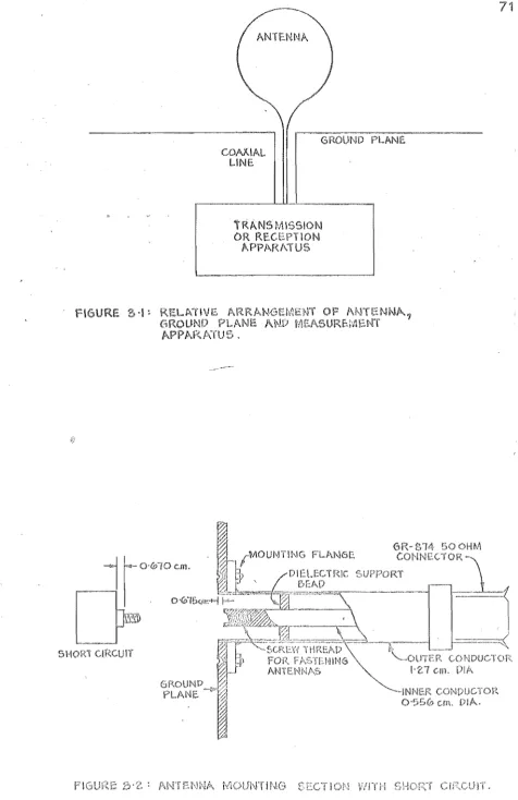
Fig. 2.1 shows two erLna,g, one transmi tt the ot receiving. The distance r is suff i for
antenna be in respect far fields. A pulse
generator, r esented s Thevenin eauivalent c cuit,
es a pulse u(t) (cal d a test pul e) which is
compared to the t i t takes to
light, 1
1,
to
speed
enna 1,
Antenna 2 is ed by a length of transmission 1
to a load impe e ZL' For simp the transmi on lines are as to be loss less spersive
. origins of t for the test pulse, the reflected transmitt s, are arranged so that the transmiss delays by the lengths L1 and L2 of transmiss
line, and separation distance r the two are removed. T ation app antenna 1 is u(t). The point pulse re onse of antenna 1
reflect back towards the
,
v1(t). The mission se response of t enna f:7 stem s
at the load enna 2. Both t se
responses are easily measureQ a sampling osc oscope (see
3).
By represas a two-port througb. antemla t
its s ering mat~ix,
(with an erisk denot
s11(t) is the impuls 1"e se response
the two antennas their whose boundary passes
describing s network by em equations can written convolution)
e of enna 2.
enna 1 and s22(t) 1(t) is the trans
(2-1)
on impulse re e of tlw antenna , and f:i.:om t
of the matrix (Montg
p.1 )
identical antennas are used
s (t) =
11 (t) .
et aL 1948,
( 2)
16
An
ortant advantage of making VHF and crowavemeasur s in the time domain is that e be s d so that unwanted reflections
from mismatch in the feeder cables (e.g ons
or joins between cables of diff c c
edance) arrive separated in time e being
measured. This is achieved by choo i long
feeder cables ffild by placing the e iciently far from reflecting objects e adequate time delays
into the reflected signal p is possible to
arrange that mismatches at e ons have negligible effect on the measurements large attentuators,
which is a distinct ional c.w.
measure-ment methods. The e e ss necessarily long
connecting cables can [)e remo measurement by
recording u(t) in a ec cll is scribed in chapter
The time which is le measuring the pulse
response (either v
1(t) or (t» before the arrival of
umvanted reflecJuions is term t vieviLLng window. It is
,
convenient to d measurement interval as the time
interval se response is to be measured.
The measurem cCll~not be longer than the vi
window, p system Cffil have a strict
time l i m i t e , Consequently "by limit
measurement ion errors are introduced when
the e e computed: these are discussed 1 er in section
.3.3.1.2.
re e is as time for vvhich i t is
as much of e response as ss le the measurem
interval be equal to the e duration.
uCt) is compared to the t takes a current se
to propagate along the antenna speed of light,
i t 1S often ssible to isolate r lections and on
from parts of an The viewing window
then need be long enough so the desired of
the pulse re onse is received. Section
2.5
des sdriving po measurements of b 1n W1re
.
.which measurement int ludes only a
all lli"1wanted s by using a
window means t the antenna em is in a ed inf empty environm Thus time
ranges can be a'ccommodat relatively d es.
Some t measurements r 1n this not
have ~)een rformed simply frequency because
e was no anechoic er nor sui table out or antenna
lable.
It is imprac time domain measurements
e on higll CHF) antennas b cause very ed to give a window of
ficient duration to le the pulse re e to be
isol ed, For example, on the basiB of measurements
r ed in Part
es a1)out 300 me
measure v
1Ct) for all
advantage of
e retained -by
of
s
s thesi,s) co cable delay
would be re ed to be able
enna designed to· erate at 20
measurem s time do:::nain c
measu~ement on sc mo Is.
a pulse is termed a narrow pulse.
18
further discussed er
7,
A graphical record a short e measurement of an enna represents a great deal of information stored in a small space. this reason i t is often difficult to
int eta It is sirable to transform pulse response equency response. This is e ecial true of
re onses from vi s of an antenna. The time hi ory of an ennas responses v
1(t) and (t) to a te pulse u(t) contain all ormat
required for c culat the antennas vo e le on coe icient at input of t antenna, p(f) , and the
enna system transfer function, H(f), within the ect bandwidth of te pulse. H(f) is transfer ction be een transmitter and rece , assuming that t
at-on is st onless, and ter r the fect of antenna s aration on phase and tude. es eqn
(2-1) in frequency domain s:
r~11
(f)LS21(f)
(2_11 )
Each le in e (2-/+ ) is t Fourier transform (FT) corresponding able e ( )
.
Upper case 1 81:18
are used for fr re es ( ectra) r case letters for signals, l.e.
get)
1:
G(f) ejThe vol reflection co icient at the of antenna 1
is 'by
8
11(f) V1(f)/U(f), (2-6)
and system er function by
(2-7)
The effe
of fr
'oandwidth of u( t) 1S defiLed to be band
es, of width W c on
F,
withinIU(f)
I
is well above the mean noise level. The 1 s of Wits V;fere c sen
peak value,
smaller t
be the points re IU(f)
I
was -20s limit was choL'lenbecause when
I
U(f)I
wast s the computat of the frequency re
were observed to deteriorate. Consequen-cly
e
F+(W/2); ( 2-·-8)
H(f) r (f),
F-(W/2)
< IfI
<where the distance r metres'is inc
of antenna sep ion on the magnj
antenna s on e is removed
(W/2) , (2 )
to remove the effect
H( ) (the effect o~
appropriate
choice of time or for vet)), Knowl both p( f) and
H( ) is required fo a proper understcuJ.u.J'Ll.F~ of the operation
an antenna tern,
The reflection co icient of an antenna es how well the aCltenna is a· s on of a ceI:~
characteri ic e Z
being a property of the enna alone, is en more us
and may be simply culated from the erred ection
co icient:
( )
For accurate c ation the fre ency response,
D(f), which occurs in denominator of e (2-6) and
(2-7),
mu not c ain any zeros or small values ofmodulus, or any rapid phase es. A eband se was
chosen ?S a te signal because of s well behaved ectrum
(see "ber it-) , rrhe centre frequency F in e (2-8)
( ) is t zero quency"
The pulse responses were sampl (as ed
following two se ions), the fre ency re ses were
culated by a digit computer, When IBlVI
c ompu"c er was us the IS were computed by the fast Fourier
transform (FFT) oritbm (Cooley Tukey, 19 ), whi
approximat s eqn(2- ) by the screte f te s es:
N~l
( ) ( ) e - j nfT G
SN f == T :s g n==O
f k k 0, ±1 , .. , ,
( 10)
N is the er of es t ? T is samp int
and == 1/2T is the st frequency. script ions the
FFT, how to use it, are given by IEEE (1 )
,
IEEE (19 ) Bergl (1969) The FFT ori atly escom~-c on t in c son strai orward numerical
integr on met , the actual am lNhi was
lable (the IB~'JI entific EA.JlM) oc ed
compute FT's (which is described er section
2.3.2),
a trapezoidal rule egration method was used because theFFT could not fitt into the memory of the tal
computer. Conse ently a typical computation time the measurements report In s thesis was two minutes. The same results are obtained whichever method us because
FFT is mere a sp algorithm for trapezoidal rule int ion (Cool et ale
1967).
Also, the ezrule is quite accurate when T is small because the oscillat kernal in
2-5a) ,
Modern. ing oscilloscopes are ide instruments to connect to automat measuring equipment, because they can be scanned a re time rate ch is convenient fOl' the scanning equipment. Analogue recordings can be made with an
pen recorder by scanning time s the recorder and time bane the ling oscilloscope simultaneously. These analogue records may be sampled manually for
$equent computer proces s method was used during a prel inary ev~luation of TF'II te que. HOlNever 1
s es are re from a number of recordings methocl is v tedious ~~d conse 1 . .
~_y l S error
sens
the srune answers
t
COllC~l S
is now avai :#:
360D--13. 4.002,
ch r input data by its transform an involved procedure to sort
vector, Consequently
In (2-10) the frequency response is cuI ed equencies ac by 1/NT. Thus accurate timing of the . sampling interval T is required to avoid errors the
frequency scale calibration.
Accurate samples of the pulse response are eas
obtained by connect t sampling oscilloscope to automat-ic data me equipment. T synchronising is simple
t measuring equipment generates a staircase scanning voltage for t sampling oscilloscope time base. Accurate
t of the les is obtained in s provided the sampl oscilloscope horizontal e scale d Ie
f or (volts per cm of deflec on) is knovn~ accurate Hovv to ibr e the sampl oscilloscope is described later in section
3.5.
A hybrid computer, wlli is a di al computer and an anal c er int ed with a data conversion and control unit, is ideal for automatically measuring
processing data from a domain antenna range, All the measurements rep ed this the s were p or::ned by an
-590
computing system. Some the measurementswere processed on-l by the same COJlput fr responses were d on a high-resolution sto
ch been special iIlt ac to t Bnd the se re es were di layed on oscilloscope screen.
drawn by an hybrid computer screen.
simultaneous di s were
al computer~
ing
ays fre ancy an
and pulse response were obtained. The two di are com-plementary: the loc on of antenna dis inuities are given by time display and ect on the antenna p ormance is given by the equency spl
Connecting a samp os lloscope to a small computer is reported by colson (1968), who scusses feasibi ty of making wideband measurements on microwave transmission line components us the TFT technique. He ludes
experiment re s to demonstrate its c abil A hybrid computer is emely versatile, and sophi cat
super-visory routines could be included the digital computer program which cul es frequency r8 onse. logic
erface allowed a control box, which was remote located at t enna range, to be erfaced the digital com-puter pro The digital computer wan then progr81nmed have overall control of the measurement system, which could be operated eit~er from t computer console or from the dupli ed controls at the antenna e~ g. 2,2 is a simpl ied block diagram of the TFT measurement system.
Several digit basic 0
computer programs were wri en and their ion is given,in Appendix 1.
use
of
a genera~ purpose c er as a controle ent for measur syst
over a hardware control er. There is
er of advantage flexibi ty
stored pro lows. Mo ic ion of the control functions correction of errors are done by the
program~ not wi Often this involves just changing
a few trG.ctions in memory, can be the co 81'
24
functions6.
The advantages a hybrid computer controlled TFT measuring tem for and microwave antennas are:
1) wideband information is obtained from a s e measurement;
2) cable and generator mismatch do not ect the measurement;
effects cable loss and di ersion are easily removed from me
4) a simul ed inf environment allows
measurements to be in relatively conf spaces; 5) simul tB.n80US lays equen re onse time
domain se re onse aid unders of an enna. tem operation;
6) e llild ease me enables many enna conI ions to evaluat Teas quickly; '1) flexibi of II ell control allows system
to e reorganised qUl (a matter of minutes) for
differ mea functions;
8) the c er can be used for other ering ions it i~ not being u for enna measurements.
However) t arbi fine resolution the fre domain measurement ds cannot be att , although the
accuracy can be approached for measurem s on and antennas by a speci sampling t clmique (Nicolson,
c measurement as scojJe\ e and software for such a
2.3.3.1 inherent in cal
It can be shovn'l (Cooley al.,1967) eqn( 0) lS
equivalent to
00
2.: G(f+2£f N) I
£=-00
-
f k 0,±1, (2-11 )N
00,
eqn(2 1) describes a peri c fm1ction GS(f) whi t superposition the non-peri c function G(f)shift by all multiples of t fundrunental period
GS(f) is said to be an ased on G(f). For es
of f within the l' re
e G(f) plus unwanted cGrttributions the aliases G(f) 1,2, ...
00,
since no actical gnallS
P
ectly bandlimited.alias error is reduced making fN 1 e, ch i equivalent to making T small. This shifts the ases furt ap and reduces t~1e ed c ons om them the e -fN
<:
f<:
creas T whilemeasurement eases N,
re es more c er more ion, thus
a compromise is nec ssary. aliasing error be reduced by deliberate bandl ting s T
of te pulses used to make s report in
this t SlS s f 0, ampli tude
crease as e incr ases" The .S VIer
26
samp oscilloscope. T was chosen to make fN f s
the dth of the s ing oscilloscope. The
of computed spec of the test ses at fN
all less than 1% of amplitudes f ::=
o.
alias error in measurement dth (0
<-the bandwidth the sampling os lloscope
cons ly less 1%.
2.3.3.1.2
all of vet) were recei would be
avo accepting eciable refle from
So, vet) must be g ed which means that, having
g interval ion N'r inning at t rece accepts (v(t) gate(t/NT)); where g
zero except for 0 <- t <- NT is unity.
s
were
Thus
f
<-
fN/5
ifis us ) lS
ssible to
environment
7 .
sen some0, the
(tiNT) lS
gating
tion gate( ) is termed R. rectangular a w.indow. A
Ie value NT was chosen for each me which
on le ion of vet), a maximum
set by the time of e ons from environment.
loss of some of vet) causes an error le
quency re onse which lS cult to e because
upon t portion of vet) which has not been measured.
so, the
V(f) vvith sine nfNT)
I
nf .the mea
11 exhibit
7
pro:n nOVl plJ.lseon
If v (t) or b .1
o VlOUS
received s lS t convolution of
of gate( se lS
tll:3 durat of vet) lS ciahly er
int then the c ed spe
les a width of close to 1/NT,
v( t) :L,s used
v
1(t) or tV'I(t) is me the context,
mean el fie parti
i '-ling po t se re onse - (t).
effect has been call response presented
leakage (Bergland, 1969), and the F ,9.3(c) clearly exhibits such ripples showing that although the chosen value
most of vet) to be received, nevertheless the
NT permitt ects of
. truncation were sensible. However, the ects of truncation were never suffici to mask t trends of the frequency responses of the measured antennas. It is also worth noting that it was not possible to identify the reciprocals of the widths of the ripples the comput frequency responses with any major physic dimension the antennas under test,
Leakage can be reduced by sampling vet) with a data window which lower sidelobes in the quency domain than has gate( tiNT) . The data windovv which was used on driving point and far field lse responses in parts II and
of this the s is extended cosine bell window scribed by Bergl
d(t) 1 , It
I "
wNT,d(t)
d(t) 0, ( )
where (1-w) is the fraction of the data to the co ine -be appli cause vet) i causal, eqn(2--12a) is only appli d for t
>
0, but is lied to st theinterval -NT " t "
°
even no measurement is madethis erval, s to the e e the trunc
28
(2-12b)
where D
1(f) is the of eqn(2-1 ) with w = 1 (i.e. d(t) is
re ): (Bl and Tukey 1958, p98). eqn
(2-1 ) with w ~ 0 can also be by convo the
values of the c ed spectra s of 1/2NT with the
we s
i,
i
andi.
gate (t/NT) cuts off vet),a data window as eqn(
g s worse re s.
edge truncat
a compromise is necessary,
sen for each measurement.
much longer t
even less vet) is
frequency re e will
lusion of noise,
An effect ch is asso
) cuts off more of it,
, the data
and reduces
a suitable
eliminates
ripple.
for w is
so, if the measurement
the me Ie duration so
, then c tations
orate because of the
ed with Ie e is call
pi fence e (Bergland, 1969). orward use of
FFT computes the fr response at discrete
quencies
record_ is
ed
shape sine
when the
which do
signal
multiple
ctral
ch are t I e s of 1 , and, because
ated at NT,
filter
required V(f) is not ally
by a set ectral windows of
fence ect becomes
being ed has fre COJlpOnents
correspond to multiples 1/NCL Con a
a component fs' which lS not a
1/NT. s component is een ~y all adjacent
Wi-~~l i s corre to level at
Thus the component at fs does not contribute properly to the
computed spectrum. For example, the peak in the frequency
response occurrlng at the resonant frequency of a narrow
band anten~a -may not coincide with a multiple of 1/NT (an
example of this is given later in section 2.3.5).
A data window such as eqn(2-12a) reduces the problem by
increasing the width of the main lobe and reducing the level
of the side lobes of the spectral windows, but the problem lS
cured either by interpolating the computed complex Fourier
coefficients or by using the easier, but equivalent, method
of computing the frequency response at a finer spacing than
1/NT. This is simple when using a straightforward numerical
integration method, but the FFT resolution (not to be
confus-ed with measure~ent resolution, see section 2.3.4) can be
increased by extending the time domain record with zeros.
Most of the frequency re,sponses presented in this thesis were
computed at 10 MHz intervals.
Finally, i t is worth pointing out that the paper by
Farber and Ho (1969) contain,s an incorrect discussion of
aliasing an.d truncation errors. Their c.omments on truncation
errors actually :::-efer to aliasing, and Vlce-versa,
2.3,3.1,3 ~iming Shif!
If the time origin ofv(t) is delayed by ~ with respect
to the time origin of u(t), then the computed frequency
response will be multiplied by exp( -~j2TIf T), by the time
shift theorem (Lathi 1965, 'section 6,15). This is a phase
error which increases linearly wi tb. increasing frequency,
The 8xperimeEtal procedures clescribed in chapter 3 are