Burst Error Correction Method Based on Arithmetic
Weighted Checksums
Saleh Al-Omar1, Atef Obeidat2
1Department of Engineering, Amman Private University, Amman, Jordan 2Department of Information Technology, Al-Balqa Applied University, Irbid, Jordan
Email: [email protected]
Received July 19,2012; revised August 23, 2012; accepted September 4, 2012
ABSTRACT
In this paper a new approach for increasing the performance of burst error correction that occurs during data transmis-sion in low-frequency channels with pulse-code modulation is proposed. The specific technique is based on the weighted checksum which is computed with arithmetic operations. It is shown that the solution proposed not only guarantees the correction of any single error burst but it also lowers the computational complexity so that procedure correction time does not depend on controlled data block length. Finally, the use of the algorithm is illustrated via the thorough presentation of an example of erroneous data transmission.
Keywords: Burst-Errors; Reed Solomon; Arithmetic Weighted Checksum
1. Introduction
The development of the information transmission tech-nologies in the computer networks and in the telecom-munication systems is inseparably connected with the problem of integrity and of ensuring high effectiveness of error detection and correction of errors which occur during data transmission.
The dynamic increase in the speed of information transmission in the buses of computer systems and the channels of computer networks brings about stringent requirements for the performance of the hardware im-plementation of the error detection and correction algo-rithm: it must ensure the realization of the operations which are connected with the rate of error detection for data transmission.
A continuous increase in the speeds of data transmis-sion in the telecommunications network systems is re-sulted in change of error character and effectiveness cri-terions of error detecting and correction. Today the main cause of data transmission errors is external impulse noise [1]. Data transmission speeds up the external im-pulse noise’s influence on few adjacent channels signals. In consequence,the group of adjacent bits of transmitted data can be distorting. Suchgroup of bits is named burst of errors. So, today bursts of bits distortions become dominating type of errors [1].
On the other hand, the dynamic increase of the data transmission speed has changed the importance such of tradition error control effectiveness criterions as number
control bits and possibilities of detecting and correction errors in rate data transmission. It is clear that in modern condition of significant speeding up of data transmission, its increasing of the importance of computation complex-ity of detecting and correction errors procedure which impose the possibilities of real time error control. On the contrary, the modern tendency for increase of speed and values of data transmission decreases the importance of such tradition error control effectiveness criterions as number control bits.
Thus, the problem of detecting and correcting burst of errors in rate data transmission is very important and requires attention for the current and future technological developments in computer and telecommunications sys-tem. This specifies the urgency and the practical impor-tance of the development of new methods and means to speed up the burst errors detection and correction proce-dures.
2. Burst Error Analysis and Existing
Techniques for Their Correction
frequency, amplitude, or phase distortion of the trans-mitted signal [2].
Unlike the errors that are caused by thermal noise, all other sources tend to give errors that formulate bursts. About the frequency of the error events only empirical conclusions can be drawn by testing under real condi-tions.
The term burst errors suggest that those errors are cor-related, i.e. if one bit is erroneous, it is quite likely that the adjacent bits have also been corrupted. When one refers to the term burst error of size m, what is meant is that the distance in bits from the first to the last error in the frame is at most m – 1 while the intermediate bits may or may not be corrupted.
Indeed, let the externally produced noise correspond to a maximum duration tn. One thing worth mentioning is that for the same bit error rate, burst errors are in princi-ple easier to deal with than random errors.For example, consider the case of frames consisted of 1000 bits and an overall error rate of 1 in 1000. If all errors were random, almost all frames would be corrupted. However, if deal-ing with burst error events of size 1000, only 1 frame in 1000 would be corrupted [3]. The disadvantage that comes with the appearance of burst error events is that error detection and correction as well as analytical mod-eling of the specific patterns is much more difficult to achieve compared with the case of random errors.
When random error is the case, the theoretical model of the less memory Binary Symmetric Channel (BSC) is being used. The BSC is not appropriate for the descrip-tion of burst error events as a channel with memory is necessary [4].
The probability that two burst errors occur is lower than the probability of the occurrence of a singular burst error. Thus, burst error multiplicity is usually considered to be equal to one in the state of the art.
With the use of special coding it is possible to distin-guish two approaches for the control of the appearing errors:
The error detection by special codes and their correc-tion by retransmitting the data block (ARQ—Auto-matic Repeat Request);
The correction of the appearing errors by applying correcting codes without the repeated transmission (FEC—Forward Error Correction).
The choice of the appropriate technology is deter-mined by the features of the data transmission channel as well as the particularities of the specific use. Thus, in wired systems for digital data transmission, in which the intensity of errors is several orders lower in comparison with the wireless channels, the use of ARQ is considered to be more effective. On the contrary, in the wireless channels the prevailing source of the transmitted errors is the externally produced noise and in this case the
inten-sity of the appearing errors is high enough to consider the application of FEC technologies to be more preferable.
In general, ARQ technology is being preferred over FEC technology as the latter demands more complicated decoding hardware and greater redundancy. This makes sense if one takes into consideration that FEC technology demands not only the knowledge of the occurrence of at least one error but also of the exact number of erroneous bits and of course of the exact positions of the corrupted bits in the affected block. Therefore, the drawbacks of error correction codes include the relatively large volume of control information, the complexity of the procedures and the decoding process. As a matter of fact, the number of control bits increases exponentially as the multiplicity of errors that are required to be corrected increases. Ad-ditionally, in the case of correction codes the computa-tions for the syndrome calculation take place even if no corruption has occurred and that causes a considerable cost in complexity [3].
For burst error correction usually the cyclic codes are utilized. Among cyclic codes which are peculated to one burs error correction, Fire, Abramson and Melay-Abram- son codes [2] can be mentioned. At the same time the most widespread is Reed-Solomon code [4] which is able to correct few burst errors. In practice, the type Reed- Solomon code for one burs error correction is most fre-quently used.
Reed-Solomon code is non-binary codes suggests the division of the transmitted block into n symbols, each of which will be consisted of m bit. With the use of 2 × h control symbols a Reed-Solomon code allows the correc-tion of every distorted bit in h symbols. However the computational complexity of the implementation of the demanded calculations is unjustifiably large. From the mathematical point of view, the procedure of distorted symbol location consists of solving of nonlinear system equations. In fact according to Reed-Solomon code tech- niques for this nonlinear system equations solving use enumeration: finding of nonzero components error loca- tion vector executed by examining all n variants. It means that computational complexity of procedures cod- ing, decoding and error correction depend on transmitted block length.
Usually, both encoding and decoding procedures are implemented with specific devices and since Reed-Solo- mon codes are cyclic, encoding as well as error control are implemented in a sequential way, namely without the ability of parallel computations. Finally, since Reed- Solomon codes compute the syndromes whether there is an error or not, computational cost increases even more.
low frequency channels or during data storage has sev-eral further crucial features and those particular features allow the proposed method to maximize its efficiency in burst error correction compared to Reed-Solomon codes. For the correction of this kind of errors, Reed-Solomon codes must be able to guarantee the correction of h = 2 × r—bit symbols, since the burst error could originate any-where in the sequence. Consequently, the total number of control symbols required in the case of Reed-Solomon is equal to 4 (4 × m bits) while the theoretical minimum is 2 × r bits. That implies that Reed-Solomon code is clearly suboptimal for the solution of the problem under study.
Another approach over the last years is the use of sim-ple weighted checksum for error correction [3]. The based on logical weighted checksum approach for single burst error correction [3] is more effective in comparison to Reed-Solomon codes: used less control bits, this
ap-proach allowed to red m
to . Using logical weighted checksum approach enhances the efficiency of single burst error control in low frequency channels, due to the decomposition of the main problem in two parts: the localization of the positions of the corrupted bits in the burst and the localization of the start point of the burst that has occurred.
uce computation complexity fro
O 4 n m
22
O 4 log n m
From the modern effectiveness criterions, the main disadvantage of logical weighted checksum method con- sists in that computation complexity of burst error cor- rection procedure depends on transmitted block length.
The aim of presented investigation is to speed up the burst error correction procedure so that it can be executed in rate data transmission.
3. Burst Error Correction
Let us consider a transmitted information block B that consists of N bits:
1, , ,2 N
B b b b , bl
0,1 l
1, , N
. Proposed method assumes that this block divided into n symbols: . Every j-th symbol X,contain
1 2m bits , , , nB X X X
n
j
1, ,j Xj
x xj1, j2, , xjm, , , so
that xj1bj1m 1,xj2bj1 m 2 jm j m
2 2
x x
1
x b
2 x 2m1
, where
m isthe maximum size of the burst. Each one j-th symbol Xj can be considered as binary number
1 2 3
j j j j jm . For every
j-th symbol Xjthere is weight coefficient Wj defined as .
D x
Wj j
The control code C consists of three components C = {C1, C2, C3}, first of which—C1 is the arithmetic sum of
odd-numbered symbols of the transmitted block:
1 1 1 1 . 2 j n j j C
D (1)Second component С2 is calculated as arithmetic sum
of symbols with even number in transmitted block:
1
2 1 1 1 . 2 j n j j C D
(2)The third component C3 is the arithmetic sum of
products symbols by its weight coefficients, whose are by one greater of symbols number:
3 1 1 n j j C j
D (3)The mentioned above control code components calcu-lated according to Equations (1)-(3) by sender are de-noted as C1S, C2S and C3S. After the calculation of the
control code at the sender side, this information is sent to the receiver in the following order: C3S, C1S, C2S, X1, X2,···,
Xn.
For example, let us consider the data block B which consists of 16 bits (N = 16) B = {1001 1010 1100 101}. If maximal number m of bits if burst equals 4 (m = 4), transmitted block divides into four (n = 4) 4-bit symbols: X1 = {1001}, X2 = {0111}, X3 = {1111}, X4 = {1010}.
Correspondently: D1 = 9, D2 = 14, D3 = 15, D4 = 5. On
the sender side the components of the control code will be computed as such:
1S 1 3 9 15 24
C X X
2S 2 4 14 5 19
C X X
;
3 2 1 3 2 4 3
2 9 3 14 4 15 5 5 C X X X
;
4
5 145.
S X
Sender sent to the receiver following bits sequences: C3S,
C1S, C2S, X1, X2,···, Xn = 1000100 00110 01010 1001 0111 1111 1010.
On the receiver side the information block and senders control code are received and using Equations (1)-(3) the receiver control code components denoted as C1R, C2R
and C3R are calculated. The receiver calculates the
dif-ference Δ using the three components computed in their end and those that were received. Indeed, = <1, 2,
3> where 1 = С1R – С1S, 2 = C2R – C2S and 3 = C3R –
C3S.
Consequently, the receiver analyses the code for the purpose of determining if the information block was transmitted without errors, for the detection of possible transmission errors in the information block and for the correction of such errors. Assuming that only a single burst of errors occurs and that this burst distorts no more than tree symbols, there may occur one of the following cases:
1) If all three components of code Δ are equal to zero, namely 1 = 0, 3 and 3 = 0, then the information block
has been transmitted without errors.
3) Control code component C2Sand first symbols X1 of
information block are distorted.
4) One or pair of adjacent control code components C2S, C1S, C3Sare distorted.
In second and third cases it is necessary to correct er-ror in information block. In last case it would suffice to determinate this type of errors.
In second and third cases there are two different vari-ants: only one symbol Xv is distorted and two adjacent symbols Xv and Xv +1 are distorted. If only one v-th
sym-bol Xv is distorted and its number v is odd than
. Consequently number 1 v can be defined by following way: 2 3 1
, 0, а 1
vR vS
D D v
3 1
1 v
(4)
Correction is executed by following way:
1
– vS vR
D D
. In a similar manner the one symbol with even number in block is corrected.
When two adjacent symbols Xv and Xv +1 are distorted
and v is odd than
1 DvR DvS, 2 Dv1,R Dv1,S
3 1 2
2 1 2
and 1 2 1 ( )
v v
v
Such as in symbol Xv the high bits are distorted and in
next symbol Xv+1 the low ones, condition 1 2 is
fulfilled. In view to above number v of first distorted symbol can be define by following way:
3 2
1 2
1. V
(5)
For correction of distorted symbols, it is need to exe-cute operation: vS vR 1 and .
In a similar manner if v is even:
D D Dv1,S Dv1,R 2 1 2 and
num-ber v of first distorted symbol can be defined by follow-ing way:
3 1
1 2
1. V
(6)
For correction of distorted symbols, it is need to exe-cute operation: vS vR 2 and 1, 1, 1.
The outlined way for burst error correction can be il-lustrated by such example. It is suggested that during bits sequences transmission: C3S, C1S, C2S, X1S, X2S,···, XnS= 1000100 00110 01010 1001 0111 1111 1010 external noise caused a burst of errors that corrupted third and fourth symbol of information block. As a result, the cor-rupted symbols have been received on receiver side, which are as: X3R = {1010}, X4R = {0010}. Correspon-dently D1R= 9, D2R= 14, D3R= 5, D4R= 4. Consequently, on the receiver side the components of the control code will be computed as such:
D D Dv S Dv R
1 2
3 3
9 5 14, 14 4 18,
2 9 3 14 4 5 5 4 100.
R R
R R
C C
C C
The difference of control code is calculated on re-ceiver side as:
1 14 24 10, 2 18 19 1
and 3 100 145 45.
Because of 1 2 then first distorted symbol has
odd number v, which according to (5) is calculated as:
3 2
1 2
45 1 44
1 1
10 1 11 V 1 3
Procedure correction of X3 and X4 executed by
calcula-tion:
3 3R 1 5 10
D D mod 25 = 15,
4 4R 2 4 1 5
D D .
If control code component C2Sand first symbols X1 of
information block are distorted then 1 0, 2 0 and 3
0, despite the fact that 1 D1RD1S and 2 1 , 31 × 2. If all mentioned conditions are fulfilled then
correction executed by the way: 1S 1R 1. If only one of control code components C2S, C1S or C3S is distorted that two from codes 1, 2 and 3 equal to
zero and one is not equal to zero. This situation can not be arising in case information symbol distorting and so can be easily defined.
D D
In the case that pair of control components are dis-torted during transmission there are two variants: pair C2S,
or pair C3S, C1S is distorted. In first variant 1 0, 2 0
and 3 0, it is clear that such situation can not be
aris-ing in case information symbol distortaris-ing and so can be easily defined.
In second variant 3 0, 1 0 and 2 0. Because
C3S is transmitted before C1S, in component C3S the high
bits are distorted and in component C1S the low bits are
distorted. It means that 3 1 and it’s simply to
show that:
3 1 2 n 1.
(7)
It is clear that in case distorting of information symbol occurs, the condition (7) can not be fulfilled, so this con-dition can be used to define the situation when pair C3S,
C1S is distorted.
4. Effectiveness Estimation
For proposed burst error correction method number k control bits is determined by the sum of size of control code components C1, C and C. It is clear that maximal
value of C1 and C2 is
2 3
2m 1
n2 n 2m1. Thus, bitsize of control code components C1, C2 is equal:
. Maximal possible value of components C3 is equal:
1
2 2
log n 2m log n 1
plicity higher than the one which allows correction. For instance, in case of the occurrence of two burst errors, the code proceeds to an erroneous correction of an un-distorted symbol. On the contrary, for the method de-scribed above there is a control mechanism of the errors that cannot be corrected so as to alert the user to request retransmission.
m
2
2
2 1 2 3 1
2 1 2 2 2 2
m
m
n
n n n n m1.
The primary advantage of the proposed method is the
efficient correction of single burst errors with an imple-mentation that demands low computational complexity both for the control and the error correction.
Correspondently, bit size of components C3 is equal
2 1
2 2 2
log 2 2
log 2 1 2 log .
m
n n
n n m n
2 m
1
For coding (control code components calculation), it needs to execute three addition and one multiplication per symbols of block. In view of the fact that modern processors contain the fast multiplier, it can be conceded that there are executed four operations per symbol. So, coding computational complexity—O(4 × n). In pro-posed method is similar to coding and, correspondently, complexity of decoding procedure—O(4× n). For single burst error correction according to (4)-(6) is required four operation of addition and one operation of division. Eventually, for correction only five processors operation are required. It means that for burst error correction op-eration time does not depend on both information block length and symbol length.
Thus, the control bits number k is equal:
23 1 4 log
k m n (8)
For Reed-Solomon codes which are also used for the solution of similar problems, the correction of a single burst error of size up to m bits in low-frequency channels demands 4 × m control bits.
The comparison of the two methods shows that the suggested one requires a trifle over control bits in com-parison to Reed-Solomon codes. For example, for the correction of a burst error the size of which is up to 8 (m = 8) in a packet of size 64 bytes (n = 64), with the use of Reed-Solomon 4 × m = 32 bits are required while with the proposed method 2 control bits
are used or 40% higher than Reed-Solomon codes need. 3 7 4 log 64 45
Reed-Solomon code single burst error correction in-cludes such procedures:
1) Solving of the system of two symbols equation for locator error vector coefficient define.
2) Location of the position of twodistorted symbols in data block. To do this, it would require searching non-zero values of location error vector by enumeration n possible variants.
Additionally, Reed-Solomon codes put restrictions on the size n of the controlled information block B depend-ing on the value of m. Thus, the block size must be up to 2m symbols or 2m× m bits. For instance, when m = 4 the information block size cannot exceed 8 bytes. On the contrary, the suggested technique which is based on the decomposition of the initial problem into the sub-prob- lem of the localization of the burst and the sub-problem of the distribution of the errors in the burst guarantees single burst error correction without putting restriction on the size of the information block.
3) Solving the system of symbols equation for location distorted bits for every distorted symbol.
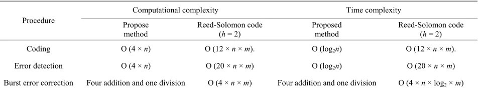
The total number of processors operation is equal 4 × n × m. For example, for the correction of a burst error the size of which is up to 8 (m = 8) in block of size 64 bytes (n = 64), with the use of Reed-Solomon 4 × n × m = 2048 processors operations are required while with the pro- posed method only five that is less than Reed-Solomon codes by factor 410. The data for comparison analysis of computation and time complexity proposed method and Reed-Solomon codes are shown in Table 1.
[image:5.595.62.538.645.736.2]Finally, in Reed-Solomon codes there is lack of a con-trol mechanism of the occurrence of errors of multi-
Table 1. Computational/time complexity both methods.
Computational complexity Time complexity
Procedure Propose
method
Reed-Solomon code (h = 2)
Proposed method
Reed-Solomon code (h = 2)
Coding O (4 × n) O (12 × n × m). O (log2n) O (12 × n × m).
Error detection O (4 × n) O (20 × n × m) O (log2n) O (20 × n × m)
The data analysis based on Table 1 shows that the use of the method based on checksum allows the substantial reduction of time complexity compared to Reed-Solo-mon code. Consequently, an increase of the speed of the encoding, decoding and error correction has been achieved.
5. Conclusions
The proposed approach enhances the efficiency of single burst error control in low frequency channels due to the decomposition of the main problem in two parts: the lo-calization of the positions of the corrupted bits in the burst and the localization of the start point of the burst that has occurred. To succeed in reducing computational complexity and speeding up processes involved, the pre-sent technique suggests the use of a conventional check-sum method and the use of the weighted version of the checksum for the solution of the first and the second problem respectively.
The main advantage of proposed approach is that pro-cedure burst error correction has computational complex-ity less than Reed-Solomon codes by 2 - 3 order and less that method based on logical weighted checksum by one order. It means that proposed approach assures signifi-
cant speeding up of burst error correction in comparison to known methods. In doing so, required control bits number increase shall be no more 45%.
It has been shown that the application of the method described in this paper lowers the computational cost of the operations that need to be executed for the correction of the burst error comparing to Reed-Solomon codes.
REFERENCES
[1] B. Sklar, “Digital Communication, Fundamental and Ap- plication,” Prentice Hall, Upper Saddle River, 2001, p. 1104.
[2] R. E. Blahut, “Theory and Practice of Error Control Codes,” Addison-Wesley Publishing Company, Boston, 1983, p. 452. [3] N. G. Bardis, O. Markovskyi and N. Doukas, “Efficient Burst Error Correction Method for Application in Low Frequency Channels and Data Storage Units,” Proceed-ings of IEEE Digital Signal Processing Conference, Corfu, 6-8 July 2011, pp. 1-6.