A thesis
submitted in fulfilment
of the requirements for the Degree of
Master of Engineering in the
University of Canterbury, Christchurch, New Zealand.
by
J. D. Marvelly.
ABSTRACT.
The principal application of stepping motors to date is in low power open loop positioning systems. It is widely known that self synchronisation offers a significant improvement in dynamic
performance in addition to step integrity. The necessary positional feedback is traditionally provided by a position encoder. However the fitting of such a device is usually expensive and inconvenient.
Previous analyses of stator current waveforms of motors driven from the conventional L/R drive have revealed rotor position dependant characteristics which can be used to provide self positional feedback. A variety of different schemes using both on and off phases have been proposed in the literature. Successful self synchronisation utilising some of these characteristics has been reported for multiple stack variable reluctance stepping motors.
When the active suppression drive is used, the variable reluctance stepping motor offers high specific output and efficiency making it a contender in controlled speed drive applications as well. Lower
manufacturing cost makes the single stack motor additionally attractive.
This research investigates the suitability of the single stack variable reluctance stepping motor to position encoderless self
synchronisation when driven by an active suppression drive and chopper current limiting.
An algorithm for obtaining the necessary self positional feedback has been developed and the equipment necessary to implement it has been designed and constructed. Certain characteristics which restrict the performance of the algorithm have been observed during operation. These characteristics have been explained in terms of the significant mutual inductances between phases inherent in the single stack motor.
A linear model of the on and de-energising phase currents has been developed and implemented numerically. The results have been used to generate theoretical torque vs speed plots. These plots show good agreement with the measured performance.
A linear model of the self positional feedback algorithm has been developed to further the analytical understanding of the advances made experimentally. The numerical solutions identify the cause of the performance restrictions and simulate the nature of the observed self positional feedback characteristics closely.
ABSTRACT.
ACKNOWLEDGEMENTS.
TABLE OF CONTENTS.
CHAPTER 1. A REVIEW OF STEPPING MOTOR CONTROL. 1.1 Introduction.
1.2 Applications.
1.3 Design, Measurement and Modelling. 1.4 Methods of Control.
CHAPTER 2. THEORY.
2.1 Introduction.
2.2 The Variable Reluctance Motor.
2.2.1 The Multiple Stack VR Motor. 2.2.2 The Single Stack VR Motor. 2.3 The Phase Inductances.
2.4 Performance Criteria. 2.5 Drive Circuits.
2.5.1 The L/R Drive.
2.5.2 The Active Suppression Drive. 2.6 An Active Suppression Drive Circuit
Linear Model. 2.7 Lead Angle.
2.8 Positional Feedback. 2.9 Self Positional Feedback.
2.9.1 Self Positional Feedback With The L/R Drive.
2.9.2 Self Positional Feedback and Active Suppression.
2.10 The Position Monitoring Algorithm. 2.10.1 Spatial Requirements of the
Monitoring Phase Inductance. 2.11 Summary.
CHAPTER 3. EXPERIMENTAL RESEARCH. 3.1 Introduction.
3.2 The Motor.
3.3 The Controller Architecture. 3.3.1 Current Sensing.
3,3.2 The Active Suppression Drives. 3.3.3 Power Supplies.
3.4 Operation Of The Slave Drive Unit. 3.5 An Open Loop Control Scheme.
3.6 Self Synchronisation With A Position Encoder.
3.7
3.6.1 Decoding.
Self Synchronisation With Self Positional Feedback.
3.7.1 Modifications To The Drives. 3.7.2 Operation Of The Modified Drive
Circuitry.
3.7.3 The Position Monitoring Circuitry. 3.7.4 Operation Of The Position
Monitoring Circuitry.
3.7.5 Decoding The Monitoring Circuit Output.
3.7.6 Coordinating Driving And Position Monitoring.
3.8 Modifications. 3.9 Surrunary.
CHAPTER 4. THE RESULTS. 4.1 Introduction. 4.2 The Motor.
4.3 4.4 4.5
4.6
4.2.1 Self Inductances.
4.2.2 Adjacent Phase Mutual Inductances. 4.2.3 Orthogonal Phase Mutual
Inductances. The On Phase Currents. The Monitoring Cycle.
The Monitoring Cycle Envelopes. 4.5.1 Monitoring Abnormalities. Characterising the Observations. 4.6.1 Pole Configuration.
4.6.2 The Effects Of Interference On Position Monitoring.
4.7 Torque Measurement. 4.8 Summary.
CHAPTER 5. MODELLING. 5.1 Introduction.
5.2 Modelling The On Phase Currents.
5.3 5.4
5,5
5.6
5.7
CHAPTER 6.
REFERENCES. APPENDIX A. APPENDIX
B.
APPENDIX C. APPENDIX D.
Solving The On Phase Current Equations. Generating Theoretical Torque vs Speed Plots.
Comparison With The Experimental Torque Measurements.
The Monitoring Current Model.
5.6.1 The Saddle Shaped Envelope.
5.6.2 The Monotonic Envelope. Summary.
CONCLUSION.
120
125
131 133 133 138 140
142
146
ACKNOWLEDGEMENTS.
I wish to acknowledge my supervisor Dr. G.R. Dunlop for his guidance during this research.
This opportunity is also taken to acknowledge Electropar ltd., the New Zealand University Grants Committee and the Canterbury University Grants Committee for their contributions towards the funding of the project. Electropar ltd. also supplied the motor used in this research and a commercial controller. IBM, Digital Equipment Corporation and the New Zealand Electricity Department are also acknowledged for the supply and funding of computing equipment which has been utilised in this research.
Personal financial assistance was gratefully received through the Todd Motors Research Scholarship (1986) and the Mercer Memorial
Scholarship (1986).
Finally, I wish to thank my parents. This research is not only the culmination of my own efforts but also of their selfless support
CHAPTER 1.
A REVIEW OF STEPPING MOTOR CONTROL.
1.1 Introduction.
The stepping motor is the most widely used motor in the field of low power precision position control. This is largely due to its incremental motion upon commutation from one phase to the next. The number of commutations or steps necessary to reach a specified target is easily determined and then executed without positional feedback. This positioning is accomplished by driving the motor synchronously from a commutation pulse train generated by the controller. This feature enables precision positional control from a simple control system and hence the widespread use of the step motor in this field.
While such a simple system is capable of precision positioning, its dynamic performance is limited. The limited performance is a
much. However like mechanical damping they generally lower the efficiency of the drive.
A second restriction on performance inherent in open loop
control is the lack of control over the rotor position relative to the detent positions upon commutation. The rotor teeth must be in advance of their next detent position at all times if the motor is to
continuously produce positive torque. The performance of the stepping motor is very dependant on the size of this angle of advance or lead. The angle in advance of the detent position at the instant of
commutation has been termed the Lead Angle and is a key variable in analysing stepping motor performance. To maximise the torque output, it is necessary to find the optimum lead angle.
The optimum lead angle is speed dependant as well as being influenced by the individual characteristics of the motor. In open loop control the required lead angle is determined by the motor speed, acceleration, stator current and load. It is usually not possible to have any control over the lead angle as the only controlled variable is the motor speed. The lead angle is set by the operating conditions defined by the above variables and usually at some non optimal value.
The optimum lead angle can only practicably be maintained by obtaining positional feedback and implementing closed loop control. Positional feedback can be used solely as confirmation of stepping, indicating when synchronisation has been lost. This simple usage of feedback while often termed closed loop control, does not directly improve the dynamic performance of an otherwise open loop control system. Such a system makes no attempt to control the lead angle, so the motor's torque output cannot be maximised. Any performance
point of poling or where synchronisation is lost.
The most advantageous use of positional feedback is in self synchronised control of commutation. Self synchronisation is the implementation of closed loop control where commutation is triggered in response to an attained rotor position. Such a system controls the lead angle. In an advanced form it is capable of maintaining the lead angle at the optimum value and therefore maximising the dynamic
performance as well as ensuring step integrity.
Considerable literature on the broad subject of maximising stepping motor performance has been published in recent years. The various aspects of stepping motor performance this literature addresses can be categorised into three main areas.
1. Applications.
2. Design, measurement and modelling.
3. Methods of control.
1.2 Applications.
This small area of the literature is primarily concerned with applying stepping motor drives to particular applications. The
experimental results supporting the use of stepping motors are
presented. The implementation of small hybrid stepping motor drives is now a popular area of research in the field of stepping motor
application. For example Ferris et al. (1981) describe the application of a standard four phase hybrid stepping motor to a high performance closed loop incremental motion control system suitable for paper feeding in line printers. The benefits of using D.C. servo motors in this application are discussed also. The results presented show that for the intended application the stepping motor equals the performance of D.C. servo motors, and more efficient and cost effective.
1.3 Measurement and Model
In addition to researching new applications for stepping motors, research into the design parameters which affect the
performance has been undertaken. This research has produced literature on motor performance measurement and on the development of measurement apparatus. Vallon and Jufer discuss (1981) a microprocessor based system which analyses the performance of a motor by minimising the time needed to reach a specified rotor displacement from zero speed. A high resolution encoder is used to implement closed loop control over a range of different lead angles. The lead angle profile necessary to maxiulise the acceleration over the speed range is recorded.
significant effect on performance. The results of programs which simulate stepping motor dynamic performance can be found in the literature.
1.4 Methods of Control.
Most literature is either partly or wholly devoted to the
control of stepping motor performance. In recent years the performance offered by stepping motors has increased significantly. This is
largely because they can be controlled efficiently by a microcomputer with minimal ancillary equipment. Improvements in the performance of micro computers and the reduction in their cost has made sophisticated dynamic control of stepping motors readily achievable and moderately inexpensive. Another contributing factor is the advances made in the performance of semiconductor switching devices. Power devices with high voltage ratings and high switching speeds are continually
becoming a smaller portion of the total cost of the drive circuits. As a result much research is being done in the area of control methods. Most of the related literature is primarily concerned with point to point slew time minimisation. This end result has prompted work on two main fronts; firstly the development of alternative energisation
methods, and secondly the formulation of new control algorithms and their assessment.
supply. The active suppression drive also features non dissipative chopper current limiting during energisation by switching the phase inductance between the energising current path and a low resistance "freewheeling" current path. These functions offer several motoring performance advantages in addition to increased drive efficiency.
Most of the control algorithm work has been aimed at improving performance in the open loop control mode. Phase plane related
techniques as used by Hammad and Mathur (1977), Taft and Gauthier (1975) • Taft et ale (1981) and Kille and Klein (1980) are a popular method of predicting the maximum acceleration and deceleration for a given combination of drive circuitry and motor. Theoretically optimal velocity profiles can be generated and then executed by a
microcomputer which are claimed to rival self synchronised control for slewing performance below resonant speed, and without the risk of dynamic instability in the target area. In addition the problems of resonance can be partially overcome by software controlled
microstepping. However it is generally acknowledged in the literature that to maximise the step motors performance for a given frame size and to guarantee step integrity, self synchronisation is required. The improvements in step motor performance can be summarised by a
comparison of the torque vs speed plots for a given motor for the two modes of control. Typically synchronisation brings about greater torque for a given speed and extends the useful speed range.
The positional feedback necessary to implement synchronisation is usually provided by a position encoder fitted to the motor.
Position encoders sense discrete rotor positions which are fixed relative to phase detent positions. To commutate phases at rotor
a controller capable of interpolating between adjacent sensed
positions. The demands placed upon such a controller can be reduced if the encoder has a resolution somewhat greater than the step resolution of the motor. This means that the encoder is capable of detecting a number of discrete rotor positions per step. If such an encoder is used, a degree of inter step interpolation is automatically
accomplished by the encoder. However for any motor with other than coarse steps an encoder of comparatively high resolution and accuracy is required. To achieve high resolution and accuracy a high level of overall precision is required. But such a device is expensive to manufacture, difficult to install and align accurately. Also it is usually required to operate without regular maintenance in an environment where dirt, heat and vibration may all be problems.
The disadvantage of using a position encoder to achieve self synchronised control could be largely overcome if some electrical characteristic of the motor could be used to provide positional feedback. It is in this area that this research effort is directed. The aim is to investigate the suitability of the single stack variable reluctance stepping motor to self synchronisation when driven by
active suppression drives with chopper current limiting. Conclusive results will reveal whether a given method could resolve the necessary lead angles to maximise the torque output of the motor.
2.1 Introduction.
CHAPTER 2. THEORY
The first chapter identifies the advantages of closed loop control of stepping motors and in particular when using self positional feedback. A system based on a single stack variable reluctance motor driven by an active suppression drive and chopper current limiting is proposed.
This chapter presents an analytical discussion of the system components which are used to produce such a system. A linear model for the phase currents of an active suppression driven motor is developed. The existing self positional feedback algorithms are analysed and a new algorithm is introduced and its theoretical performance is analysed.
2.2 The Variable Reluctance Motor.
The variable reluctance stepping motor is characterised by having a soft iron multiple pole rotor. In producing torque it relies on the principle of variation in the flux path reluctance between the stator and rotor poles as the rotor rotates. The poles are identified electrically as regions of minimum path reluctance and they are
identified mechanically as "teeth" on the stator and rotor. The torque exerted on the rotor can be shown to act in the direction of
between the stator and rotor poles. The attraction leads to alignment of the poles.
There are U;lO main types of variable reluctance (VR) motor) the multiple stack and the single stack motor.
2.2.1 The Multiple Stack VR Motor.
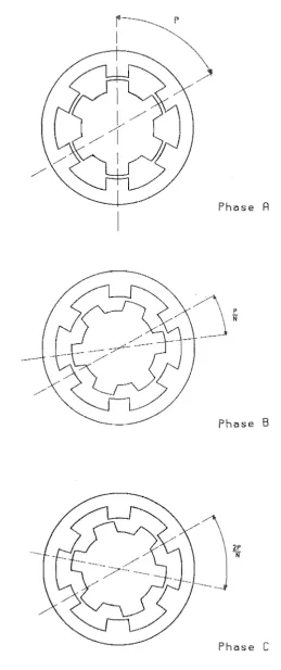
The multiple stack construction is so named because each phase has its own stator section which is magnetically independent from all the others. The motor is constructed through the axial "stacking" of all the phases. Each stack usually has its own section of rotor, the teeth of which do not continue into the next stack. The relationship between the teeth in different stacks of a typical three phase
multiple stack motor is shown in figure 2.1. The stator and rotor characteristically have the same number of teeth. The rotor teeth in each stack are shovlO to be angularly misaligned with respect to the stator teeth in all the other stacks. Alternatively, the stator teeth may be equivalently misaligned between phases. Whether the
Fig 2.1
Phc:lse A
Phase B
2P
N
[image:18.595.208.468.86.705.2]2.2.2 The Stack VR Motor.
In the past most VR motors have been of the multiple stack construction but over the last decade the single stack motor has
become increasingly more popular. The main reason for this is the high cost of manufacturing the multiple stack motor together with
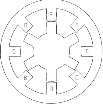
increasing demand for low cost motors. The single stack motor differs principally in that all of the phase windings are incorporated in one stator section. Unlike in the multiple stack motor the stator and rotor require a different number of teeth. The difference is usually by the number of stator teeth per phase. With this arrangement, like the multiple stack motor, one electrical cycle moves the rotor one tooth pitch. Figure 2.2 is a schematic diagram of the teeth
arrangements of a single stack four phase motor. Commutation in the phase sequence A,B,C,D causes detenting in that sequence. However the rotor rotates in the opposite sense to that of the field path unlike in the multiple stack motor where the location of the field moves axially amongst the stacks. Because an electrical cycle moves the rotor one tooth pitch, the electrical angular velocity is greater than the mechanical angular velocity by a factor of the number of rotor teeth.
2.3 The Phase Inductances.
R
c
c
R
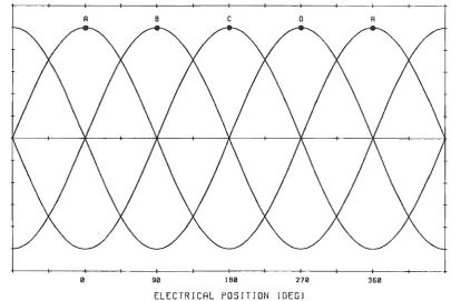
[image:20.598.138.476.193.553.2]the motor to be made. A theoretical plot of the phase inductances as functions of position within the electrical cycle is shown in figure 2.3. The phase inductances are represented sinusoidally. In practical motors the inductance variation not exactly sinusoidal because of saliency in the pole configuration. However over much of a motor's
,
electrical cycle the inductance variation is almost sinusoidal.
Figure 2.3 shows the ninety degree shift in electrical position between adjacent phase inductances inherent in the four phase motor. The detent positions are located as the points of maximum inductance and are labelled according to phase. The points of minimum phase
inductance represent the rotor positions of maximum misalignment between the stator and rotor poles for a given phase. The two step separation between minimum and maximum inductance of a given phase can be seen.
2.4 Performance Criteria.
The performance of a variable reluctance stepping motor is a function of a number of variables. However the cumulative effect these variables have on performance can be expressed in terms of the
resulting phase current and its time gradient as functions of rotor position.
w u z a:
I-u
::J Cl
Z
Fig 2.3
A 8 c o
90 160 270
ELECTRICAL POSITION IDEGJ
Theoretical phase inductances.
A
[image:22.595.117.523.292.563.2]A general and complete expression for the voltage across a phase as a function of time can be written (cf. Kuo 1979). The
expression is derived from consideration of the time rate of magnetic flux linkage change within the phase inductance. The total flux
linkage can be expressed by the sum of a number of terms involving the product of inductance and current. The expression is derived
rigorously by Kuo (1979) so the derivation is not reproduced here. The general expression for the voltage across phase k of an n phase motor is,
)
(2.1).
When expressed in terms of the transformational, motional and saturational components, this expression becomes,
(2.2).
The transformational voltage is,
(2.3) •
This component is the summation of voltages induced in phase k through current change in the self and mutual inductances. The motion induced voltage is,
n
2: ( (2.4) •
change in the self and mutual inductances with rotor position. The saturation induced voltage is,
(2.5).
This component is the summation of voltages induced in phase k through change in the self and mutual inductances with current. Saturation imposes a current dependency on the phase inductance, causing a reduction in inductance with increasing saturation. A current dependant inductance at a given value of current is termed the incremental inductance at that current, and it is this value of inductance which must be used for exact calculations at significant portions of the rated current. In practical stepping motors, the rotor and stator teeth are subjected to the greatest flux density and are typically saturated when operating at high currents. This saturation is known to affect the performance of the motor. The inclusion of saturation terms renders equation 2.1 nonlinear and subsequent torque equations without closed form solution. Linear models which omit the saturation terms in equation 2.1 can be solved. While not exact these models are still useful as they illustrate how certain variables affect performance.
The torque output can be calculated by applying the principle of virtual work and considering the field energy decrease with respect to rotor position. A rigorous derivation of the torque output with rotor position expected by the linear model is also presented by Kuo
T (2.6) .
This expression includes both the self and mutual torques. It can be seen that the self torque produced is proportional to the current in that phase squared and the rate of inductance change with rotor position. In practical motors operating near rated current, saturation effects reduce the rate of inductance change with rotor position. This in turn reduces the torque output below that predicted by the linear model.
2.5 Drive Circuits.
The type of drive circuit used with a stepping motor governs the rates of current rise and suppression (decay) in the phase
windings and hence the performance. The current which can be achieved during running is limited by the electrical time constant of the phase winding and drive circuit, the asymptotic current value and the
motional voltage term of equation 2.1. This is particularly so at high speed where the time constant may be a significant portion of a
phase's excitation period and the motional voltage term increases to a significant portion of the supply voltage. The motional voltage is in opposition to the power supply voltage and in effect reduces the asymptotic current. To obtain high torque output at high speed it is therefore necessary to have an energising circuit with a high
be a small portion of a phase excitation period, the current will approach the asymptotic value. This is likely to be many times the rated value if good high speed performance is to be achieved,
potentially resulting in damage to the stator windings. Some means of low speed current limiting within the drive circuit which does not significantly decrease the current rise time is therefore necessary.
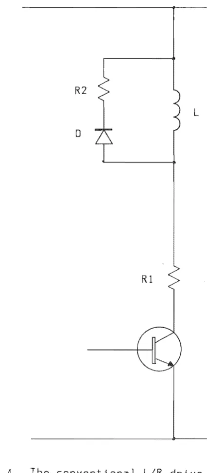
2.5.1 The Drive.
The usual method of meeting the drive circuit requirements is the L/R type drive, sho\VTI in schematic form in figure 2.4.
The resistor Rl limits the current to a safe maximum value when the motor is running at low speed or at rest. When the phase is
dissipation in the current limiting and suppression resistors becomes excessive, so there is a practical limit to the performance this type of drive can offer. This is particularly so for large step motors where stator currents can be in excess of 10 amps.
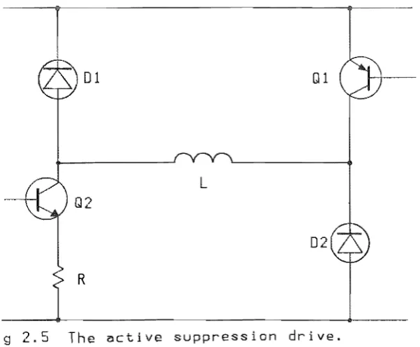
2.5.2 The Active Suppression Drive.
A drive system which overcomes the dissipative problem is the Active Suppression Drive (cf. A. Cassat 1977). This drive differs from the L/R drive principally in that it is configured to return the field energy of a de-energising phase to the power supply. In this way the de-energising current is not dissipated at the end of the step but used for excitation of the consecutive phase. In addition to
de-energising current salvaging, this type of drive usually
incorporates non dissipative current limiting through chopping of the energising current. The schematic form the drive circuitry takes is shown in figure 2.5 and the characteristic current waveform during one whole cycle is shown in figure 2.6.
The current waveform exhibits three distinct regions. Each region characterises one of the three different functions which the drive performs. These functions can be termed as follows.
1. Energisation (current rise)
2. Freewheeling (large time constant current decay)
01 Q1
L
Q2
02
R
Fig 2.5 The active suppression drive.
I /
/ /
/ '
/ ' /'
Fig. 2.6
\
\ \
\
\
\ \
\
\ \
\
"
"
+ve asymptote (VIR)
-Ve asymptote ____________ ~~ ____ __
[image:29.595.153.512.82.739.2] [image:29.595.213.514.102.350.2]Energisation is commenced by simultaneously turning on the two switching devices Ql and Q2 of figure 2.5. The energising current then passes through the current sensing resistor R and is allowed to rise until it reaches a preset level Imax. Current Imax is detected when the voltage across R exceeds the prescribed level. At this point switching device Ql is turned off and the current is allowed to
"freewheel". The freewheeling current circulates in the circuit formed by diode D2, the switching device Q2 and the current sensing resistor R. The time constant for this circuit is large so the freewheeling current decays slowly, however during chopping, the large time constant is advantageous as the rotor is mid-step and a positive torque is produced by the freewheeling current. When the current has decayed to the minimum level Imin, Ql is once again turned on. This reverse biases D2 and the current in the phase rises until Imax is reached and the cycle repeats, maintaining a controlled mean current. Owing to the lack of current limiting resistor, the asymptotic current is very high, albeit with a large time constant. However a very high asymptotic current ensures moderately rapid current rise.
This type of drive also places tighter control on the
2.6 An Active Suppression Drive Circuit Linear Model.
A linear model of the active suppression drive has been developed in the course of the research and is described as follows.
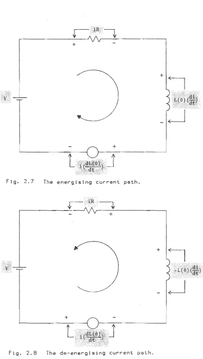
The generalised form of the energising current path can be represented as shown below in figure 2.7. The current in this circuit is the solution of,
+ i( R + (dL(O)) ) dt = V (2. 7)
where the terms are, the supply voltage, the resistive voltage drop, the self induced voltage and the motional voltage. The rate of current rise is,
=
V - iC R + (dL
d:)) )
L(O) (2.8) .
The de-energising circuit can be represented in a generalised form as shown in figure 2.8. The current in this circuit is the solution of,
L(O) (di) dt - 1 . ( R + CdL(O))) dt = V (2.9).
When expressed in terms of the current gradient, the absolute rate of current decay is,
=
. (R (dL (0)) ) V + 1 + dt
+
t
Fig. 2.7 The energising current path.
iR
r
~
, -_ _ _ _ _ _ _ _ _ _ _ _ _ _ _ _ - - J , -_ _ _ _ _ _ _ _ _ _ _ _ _ _ _ _ _ _ - ,
+
+
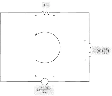
[image:32.595.120.517.73.774.2]The freewheeling circuit can be represented in a generalised form as shown in figure 2.9. The current in this circuit is the solution of,
(2.11).
The absolute rate of current decay is,
)
:: (2.12).
It can be seen in the energising circuit representation of figure 2.7 that the motional voltage opposes the power supply voltage and reduces the rate of current rise. For a four phase motor, this is so for the two steps prior to detent, where the phase inductance increases as the rotor approaches the detent positions. Beyond this region where the phase inductance decreases as the rotor approaches detent, the motional voltage term adds to the power supply voltage and the current gradient will be increased. However energisation in this
region only occurs at high speed and even then begins near the end of the region. The phase currents will therefore be low and the motional voltage term will hence be small in magnitude. Therefore practicably, the motional voltage only serves to decrease the rate of current rise.
In the de-energising circuit representation of figure 2.8, the motional voltage adds to the power supply voltage and increases the rate of current decay. This is the case when de-energisation occurs during either of the two steps immediately prior to the detent
+
, (dL(e))
;t dt
+
Fig. 2.9 The freewheeling current path.
[image:34.595.161.522.199.508.2]step range, the motional voltage opposes the power supply voltage, and the rate of current decay is reduced. In practice this does not happen to any significant extent because at high speed where the motional voltage is significant, de-energisation occurs well within the two step range of increasing phase inductance.
The freewheeling circuit is represented in figure 2.9. This circuit is related to the de-energising circuit. The difference lies in the absence of the power supply voltage. This absence allows the current to decay naturally in accordance with the circuit time
constant. Consequently the current decay is considerably slower than in the de-energising circuit. The slow current decay during
freewheeling is desirable. The rate of freewheeling current decay plays a role in the low speed efficiency of the drive but has no influence on the high speed performance.
It can be concluded that the rate of current decay during de-energisation is generally increased by the motional voltage, whereas during energisation the rate of current rise is generally decreased. As the rate of current decay is typically faster than the rate of current rise, the de-energising current has usually reached zero in less than one step at high speed. At low speed the
2.7 Lead
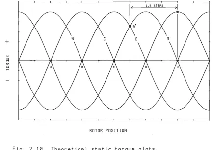
The position of the rotor teeth relative to the stator teeth of a phase as it is energised, has a significant effect on the torque output of the motor. This angular displacement of the rotor teeth in advance of the detent position of the phase when it is first energised is termed the "lead angle", and is illustrated by the theoretical static torque plots for a four phase motor in figure 2.10.
Static torque plots are plots of holding torque variation with rotor position and are generated by measuring the torque necessary to hold the rotor stationary over a range of rotor positions. In
theoretical plots a sinusoidal torque variation with rotor position is usually assumed. The detent positions coincide with the points of zero torque output, from where a rotor displacement in either direction produces a torque acting in the opposite direction, i.e. a restoring torque. The restoring torque results from an increase in the flux path reluctance as rotor is moved away from the detent position. The other points of zero torque are meta-stable positions only and a
displacement in either direction from one of these positions will cause the rotor to come to rest at an adjacent detent position. The detent positions are labelled according to phase, points A on the rotor position axis being the detents of phase A and the meta-stable points of phase C etc.
+
ROTOR POSIT I ON
[image:37.595.88.521.268.573.2]illustrated by the envelope which contains the torque plots of all the phases. For the theoretical plots shown, this lead angle is 1.5 steps. The point AI shows where Phase A is energised to produce a 1.5 step
lead angle for positive rotation. At greater speed however
energisation must occur in advance of this position. This corresponds to a greater lead angle. The advance is necessitated by the finite rise time of the energising current. To achieve high current in rotor positions where it can produce high torque output, it is necessary to start energisation of the phase earlier. This requirement is
compounded by the current limiting effect of the motional voltage which increases with speed.
Analytical derivations of the optimum lead angle for an L/R driven motor as a function of speed have been performed by Acarnley and Gibbons (1982), Rahman and Bell (1984) and Tal (1982). These
derivations lead to the same final result. Acarnley and Gibbons (1982) express the result as an angular advance on the static torque lead angle, termed the switching angle. Their analysis yields,
(2.13)
where p is the number of rotor teeth, L is the mean phase inductance, R is the total phase resistance and w is the electrical angular
velocity.
This result is obtained through consideration of only the D.C. and fundamental components of voltage and current, and neglects
the higher frequencies. A sinusoidal variation in phase inductance with rotor position is also assumed. Generally, in a practical motor this is only true for a portion of the phase inductance versus rotor position plot. However the phase inductance also varies periodically and as with the voltages and currents, only the fundamental component of the variation is considered in the derivation. With respect to the accuracy of the other assumptions made, the variation of phase
inductance with rotor position may also be considered wholly
sinusoidal. Saturation effects are neglected so that the nonlinear equations are avoided and an analytical solution can be obtained. This approach is supported by the fact that at high speed where the result is of greatest interest, the currents obtainable are lower and the extent of saturation is much reduced. Within the simplifying
assumptions made equation 2.13 predicts the variation in lead angle with speed necessary to maximise the torque output. Calculated results yield values of optimum lead angle which are in reasonably good
agreement with experimental results (Acarnley and Gibbons 1979). The result is also applicable to the active suppression driven motor but only at very high speed when the phase current is not
chopped.
2.8 Positional Feedback.
To operate a step motor at or near the optimum lead angle over a wide range of speeds and loads requires closed loop control through self synchronisation, and therefore positional feedback. The
termed a position encoder. Position encoders are fitted to the frame of the motor and sense the relative position between the stator and parts with relative motion. The most widely used of these techniques are optical and Hall effect proximity detection.
A simplified optical encoder assembly is shown in figure 2.11. The rotating component is a disc with uniformly spaced slots. As the disc rotates with the rotor. the light beam between a source and a sensor is periodically interrupted. If one sensor is used. the resolution of the encoder is equal to the number of slots. If two sensors are used in quadrature. the resolution is doubled and
direction detection is also possible. The resolution of the encoder can be increased further by adding extra sensors to the encoder. However the task of decoding the outputs from all the sensors into a contiguous pulse train and detecting rotation direction becomes increasingly more complex.
True positional feedback requires either continuous monitoring or the ability to interpolate between discreetly sensed rotor
positions. Position encoders usually only sense one or two discrete positions per step, necessitating interpolation. Usually interpolation is achieved by starting an electronically implemented time delay when the sensed rotor position immediately in advance of the desired
commutation point is signalled by the encoder. The commutation point and hence the lead angle is changed by varying the length of this delay. To produce a given lead angle requires knowledge of motor speed at any instant. At high speed a small change in the delay period
brings about a significant change in the lead angle. This necessitates a very stable delay period if consistent performance is to be
Fig. 2.11
R
Sensors ~
B~'
Optic~l encoder assembly showing two sensors
the delay period, a much larger delay is required to produce the same lead angle. If the motor is to operate over a wide speed range, a delay which can be varied over a wide range with high accuracy, repeatability and in accordance with speed is required.
2.9 Self Positional Feedback.
The variation of the phase inductances with rotor position is the fundamental criterion which self positional feedback and hence encoderless self synchronisation is based on. Successful encoder less self synchronisation of motors under the L/R drive has been reported
(cf. Kuo 1979, Jufer 1981 and Jufer and Campiche 1981) however for motors driven by the active suppression scheme it has only been discussed (cf. Acarnley et al. 1985).
2.9.1 Self Positional Feedback With The Drive.
The techniques used with the L/R drive are well documented in the literature. These methods have been developed as a result of the unquestioned use of the L/R drive over a long period. Principally these techniques rely on detecting current extrema in either the on or off phases. Typical current waveforms are presented and analysed by Kuo (1979). The general phase voltage equation 2.1 can be analysed qualitatively to indicate what the criteria are for current extrema.
neglecting mutual and saturational terms as well, equation 2.1 reduces to,
Vk(t) (2.14).
It can be seen that the conditions for obtaining extrema in the on phase current depend on applied voltage, current limiting resistance and motor speed in addition to phase inductance variation with rotor position. If extrema are to be obtained, equation 2.14 must hold at some point during the step. This requires that R be matched to the motional voltage term and the current. At high speed it is necessary that R be kept small whereas at low speed, a higher value of R is required.
It is clearly inconvenient to vary the value of a resistor which is required to carry high current and dissipate appreciable power. Also, the value of R required to set the operating conditions and that required for monitoring may be in conflict. To produce the desired lead angle at a given speed, the value of R must be chosen to satisfy equation 2.14 at the correct point so as to provide an
extrema. This value of R may produce lead angles at other speeds which are not only far from optimal, but which may not permit
synchronisation of the motor. Typically the on phase current displays only one extrema, this being a local maximum, although at low speeds current waveforms exhibiting a maximum followed by a minimum have been reported. Typically only one detected rotor position per step is
possible with on phase monitoring.
resulting equation is,
(2.15).
The non trivial solution of which
:: 0 (2.16),
The major advantage of off phase monitoring is the availability of more than one phase for position monitoring. Extrema occur at
different phases at different tinles. For example on phase monitoring can be used during starting, and as the speed increases, monitoring can be changed to the off phases.
The performance of all extrema detecting methods is subject to the motional voltage characteristic of the motor. This individual characteristic may in many instances preclude self synchronisation. Also, the added complexity of the drive circuit modifications
necessary to achieve effective self synchronisation over a wide speed range may make the scheme unattractive when compared with fitting a position encoder. Further, the sensitivity of extrema detecting methods is a function of the curvature or second derivative of the current waveforms thus making them very susceptible to noise generated by switching transients.
In conclusion, success with this type of positional feedback scheme is not assured.
2.9.2 Self Positional Feedback and Active Suppression.
The principle publication in the field of obtaining self
positional feedback from motors driven by the active suppression drive is titled "Detection of rotor position in stepping and switched motors by monitoring of current waveforms" (P.P. Acarnley et al. 1985). This publication has served as the starting point for the advances made in this research.
rise time of the energised phase at aligned and misaligned
rotor-stator tooth positions. In these positions, the change in phase inductance with rotor position is zero and hence the instantaneous motional voltage is also zero. This implies current rise times which are speed independent. It is suggested that the current rise times which correspond to the zero motional voltage rotor positions can be detected. However the current rise time is still subject to the effects of saturation, and it is not assured that a given rise time corresponds to a unique rotor position over the large current range typically encountered over a whole step. Furthermore, zero motional voltages do not occur at useful rotor positions for self
synchronisation of the four phase motor used in this research. Aligned positions occur at detent and misaligned positions which are two steps in advance. Such positions will yield lead angles in the consecutive phase of one and three steps respectively. A one step lead is non optimal at any speed, being less than the lead angle for maximum static torque. A three step lead angle is extreme, and the motor may not produce sufficient torque in the positive direction to sustain synchronisation at any speed.
The second technique proposed monitors the current rise time during low level current chopping in a normally off phase. The current
approximating the ideal continuous position monitoring. As with the on phase, the current in the off or "monitoring" phase is measured by observing the corresponding voltage across a current sensing resistor in the energising current path.
Acarnley et al. (1985) do not consider the effects of the mutual inductance between the on and monitoring phases. Only in a multiple stack motor implementation of this scheme is the flux leakage from the on phase into the monitoring phase negligible.
Using the active suppression drive linear model, the energising current in the monitoring phase may also be described by equation 2.7. The ratio of monitoring phase current to on phase current is small. Therefore to obtain signal voltage amplitudes in both on and
monitoring phases which can easily be analysed, it is necessary that the value of the current sensing resistor in the monitoring phase be appropriately increased. The effect this has on equation 2.7 is to make the resistive voltage term swamp the motional voltage term to the extent where the motional voltage term can be disregarded, so equation 2.7 reduces to,
(2.17)
which has the solution,
(2.18) •
This is the familiar itt) expression for rising current in a linear R/L circuit.
chopping is large and unless steps are taken to increase the rate of current decay, the frequency of chopping and hence monitoring is
limited. The chopping rate can be increased by reducing the width of the hysteresis band between the current limits Imax and Imino But in the interests of good noise immunity, it is desirable to chop between broadly spaced current limits and to force the phase current to decay rapidly.
The inherently rapid current decay of active suppression can be employed at the end of each rise time measurement, rather than
allowing the current to circulate in the freewheeling circuit. The advantage of using active suppression during the monitoring cycle is illustrated in figure 2.12. The amplitude of the monitoring current can be made larger for the same length of monitoring period. The enforced current decay in the monitoring phase can also be described by equation 2.9 because the de-energising current path of the
monitoring phase is identical to that of the on phase. The
resistance in the de-energising current path therefore very much lower than that in the energising current path. As the resistive voltage drop and the motional voltage in the monitoring phase during de-energisation are both very small compared with the transformational voltage, they can be neglected and equation 2.9 reduces to.
v
(2.19).....,
C
QJ L L
J
U
01
C
...
L o
....,
...
C
o
::E
Fig. 2.12
- Imax (~ctive suppression)
- - - - \ - - Im~x (freewheeling)
t
Monitoring current chopping:
2.10 The Position Monitoring Algorithm.
An algorithm was devised in the course of the research which is derived from the second method described by Acarnley et al. (1985). It has the advantage of being simpler to implement in terms of circuitry. The algorithm is to repeatedly energise the monitoring phase for a fixed period T and then measure the peak current reached at the end of this period rather than measure the time taken for a rise to a set level. The rotor position can then be derived from a voltage
measurement rather than a time measurement.
The algorithm is illustrated in terms of the monitoring phase current in figure 2.13. The peak current during each monitoring cycle is observed as the maximum voltage across the current sensing
resistor. This voltage is then compared with a reference voltage. If the first cycle shown is that obtained at maximum phase inductance, the increase in the peak current of subsequent cycles results from the decrease in the phase inductance with rotor motion. Monitoring of this phase continues until the reference voltage has been exceeded. Then a new phase is monitored with an equivalent starting position. If the two consecutive phases are electrically identical and the motor speed is constant, an exact repetition of the monitoring history of the first phase will result. Through decreasing the reference voltage, earlier cycles will exceed the reference voltage then the point of commutation will be advanced. The commutation advance means an
/
...,
c
T
(JJ
l. l. ::;l U
01
C ..-<
l. 0
..., ..-<
C
0
:E::
t
Fig. 2.13
2.10.1 Spatial Requirements of the Monitoring Phase Inductance.
In the four phase motor under single phase excitation there are always three off phases, but only two are at zero current during the whole of a given step. Only these two phases are available for
position monitoring. These phases are the first leading and orthogonal (second leading) phases. The first and most fundamental requirement of the monitoring phase that the inductance at the point of
commutation must only occur once per step otherwise premature
commutation will occur Premature commutation in one phase may have a compounding effect leading to further erroneous commutations and the subsequent loss of synchronisation.
The phase inductance plots reproduced in figure 2.14 show the theoretical rotor positions beyond which this first requirement is not met. The rotor positions where the inductance of a phase is the same at the beginning and end of a step bound the region where the first requirement is met. It is not necessary for the inductance to decrease monotonically for the entire step. However for reliable position
detection, it is preferable that the decrease in monitoring phase inductance with rotor position is monotonic for most of a step. For these reasons the most suitable off phase to use is the orthogonal phase. This phase detents two steps in advance of the on phase detent position and as can be seen in the phase inductance plots has a
monotonic decrease in inductance for the whole of this two step range. Referring to figure 2.14, let phase A be the on phase with points A its detent positions, and its orthogonal phase C be the
LU U
Z
a: I-U ::::l
CJ
Z
LU U Z
cr.
I-U ::::l
CJ
Z
0-;
1\
15
15
90
ROTOR POSITION
30
ROTOR POSITION
45 60
Fig. 2.14
4S
end of the step is between the intersections with phases Band D, Therefore the step over which phase C is monitored must begin between the two points where phase C intersects with phase B. This defines two points in advance of the phase A detent position. These points
correspond to lead angles of 2.5 and 0.5 steps with respect to the on phase, A. This implies that the lead angle must be less than 2.5 steps
(37.5 degrees) and greater than 0.5 steps (7.5 degrees).
A second requirement of the monitoring algorithm is that the inductance of the consecutive monitoring phase is greater than the inductance of the present monitoring phase. If this criterion is not met, the monitoring voltage of the consecutive phase will exceed the reference voltage during the first monitoring cycle. An erroneous commutation will then result and synchronisation may be lost.
Inherent in the ninety degree shift between the inductances of the four phase motor are regions where this second criterion not met. The regions where it is met are bounded by the rotor positions where adjacent phases have equal inductance. The phase inductance plots of figure 2.14 show these rotor positions. Let phase A again be the on phase and phase C the monitoring phase. Commutation from phase D to phase A had to occur between the points where phase Band C have equal inductance. From figure 2.14 these positions are 2.5 and 0.5 steps ahead of the detent position for phase A. As a result only lead angles less than 2.5 steps and greater than 0.5 steps can be produced. This is the lead angle range imposed by both monitoring phase
inductance requirements.
rising peak voltage to the reference voltage and can therefore only be applied in regions of decreasing monitoring phase inductance. The limitation can be seen in 2.15. where now phase D is the on phase and phase B the monitoring phase. Commutation to phase A as the on phase cannot occur closer to the phase A detent position than the minimum inductance position of phase B. This characteristic imposes a one step or 15 degree minimum lead angle.
2.11
The position monitoring algorithm applied to a four phase variable reluctance stepping motor can theoretically generate lead angles in the range of 1 step to 2.5 steps. As is shown in the computer simulation of the drive system (chapter 5) 2.5 steps is an extreme lead angle and is only required at very high speeds. The minimum required lead angle is 1.5 steps, this being the lead angle which develops the maximum static torque output.
CHAPTER 3.
EXPERIMENTAL RESEARCH.
3.1 Introduction.
A number of stages of development in the experimental equipment were necessary in constructing the closed loop control system analysed in the previous chapter. This chapter details the most major
developments.
3.2 The Motor.
The motor used was an Oulton type PLDl12 rated at 4kW
continuous output at 1500 rpm. This is one of a range of four motors covering a maximum continuous output range of 4kW to 22kW.
The PLDl12 like the other motors is a single stack four phase variable reluctance motor. The stator has one pair of poles per phase and therefore has eight teeth. The rotor has six teeth which have a 5 degree skew over their length. The motor is designed for two phase energisation and is supplied with two phases pairs wired in series within the motor. Only the six terminations are brought out to the terminal box. To enable single phase operation and to have the phases electrically independent it was necessary to modify the motor.
A B
c
o
A' B •
c·
0'Fig. 3.1
configuration produces 15 degree steps or 24 steps per revolution,
ller Architecture.
The preliminary work consisted of developing the circuitry necessary to drive the motor. Independent identical circuitry was constructed for each phase with the exception of the power supplies which are common to all four phases. A block diagram of the circuitry for one phase is shown in figure 3.2. This circuitry performs the active suppression and chopper current limiting but can be divided into three main sections. These are the current sensing circuitry, the active suppression drives and the power supplies. This circuitry is constructed in the form of an independent, slave drive unit which performs the chopper current limiting for each phase about an
adjustable limit. The unit is operated by selecting the phase to be energised with external equipment. Communication is made with the unit via a 4 line connection in the form of a four element bit pattern. This arrangement offers complete versatility in the selection of the on phase. Furthermore, it was envisaged that the equipment used to control the slave unit would be subject to a number of developments and should therefore be externally situated.
3.3.1 Current Sensing.
..,~ 01 01
(t;I\
V
f-....-CV
~(~
-
I"""T
02 Q2 ~
Power supplies """=
;=--=!==-
-:::::=-Rctive suppression drive. """=
=-
"'-~
,./p
~
K
V
Rd
Current sensing
15k
~R
13k
~
~:
330k
A A l~ 470
3k9
Phllse enllole
12k
Q2
4N26
IN4148
BC547
'v 1+
lk5
6k8
Rd
10.2 10.01Fig. 3.3 The current sensing circuitry
Principally, it comprises a current sensing resistor Rd, voltage amplifier, reference voltage, comparator and a switching transistor. The voltage developed across the current sensing resistor is first amplified to a level where it can be more readily compared with the reference voltage by the comparator. The mean current during chopping is set to a specified level by varying the reference voltage at the non inverting input of the comparator. This reference voltage is produced by a potential divider then buffered by a voltage following amplifier which supplies the low source impedance necessary to
accurately set the hysteresis levels. The comparator functions with hysteresis levels which set the chosen upper and lower current
chopping levels. The difference between the hysteresis levels and the current rise and fall rates in the phase determine the frequency of chopping. The output state of the comparator is passed to the high voltage regions of the drive circuitry via the isolation of an
optocoupler. The input to the optocoupler is buffered by the switching transistor which unloads the comparator output and passes the high currents necessary to minimise the propagation delay.
3.3.2 The Active Suppression Drives.
The drive circuitry is shown in figure 3.4. It has been
01
81225
02
2x L~~l~~ 8Y225
Fig. 3.4
555
If<
Phase en"ble
The ~ctive suppression drive.
4N26
Current sensing circuitry.
U1
devices can be used for Ql and Q2. The benefits of using the
complementary configuration can be seen when driving of the MOSFETs is considered. The devices are biased on by applying a voltage of
appropriate polarity between the gate and the source. When
complementary devices are used, P channel devices are used for Ql and their source terminals are connected to the power supply rail. The devices for all the phases can therefore be biased on by a common auxiliary supply voltage tied to the power supply rail. However the use of P channel MOSFETs limits the power the drive can deliver as at present the best readily available devices do not have the high
voltage rating of N channel devices. The alternative is using N channel devices for Ql. However their sources would be at independent voltages which vary in accordance with the voltage across the phase they are energising. This necessitates independent supply voltages to bias QI for each phase. These voltages must be able to "float" with the source voltage of each Ql and therefore must be isolated from each other and the power supply rail.
Despite the voltage rating limitation of the P channel devices, the complementary configuration was chosen because of its relative simplicity. Paralleled pairs have been used for both Q1 and Q2. The devices selected have a drain/source rating of -160 V. This is less than the voltage rating of the motor and limits the output power, but it still enables sufficient performance to fully investigate closed loop control using self positional feedback.
The output from the optocoupler is first buffered. The buffer is necessary in order to switch QI rapidly. Several specialist
assured. It was therefore decided to develop a circuit using readily sourced components. The LM555 timer I.C. was found to function very effectively as a Schmidt trigger and buffer. Within the 555 are two comparators, a potential divider with junctions at 1/3 and 2/3 of supply voltage and an RS type flip-flop. The comparators can be configured to toggle the flip-flop when the input voltage passes through the 1/3 and 2/3 of supply voltage. The Q output of the
flip-flop is buffered with a complementary output stage which enables the 555 to source and sink high currents. This makes it suitable for high speed driving of a capacitive load such as a MOSFET gate source
junction.
3.3.3 Power Supplies.
The main power supply which is used for driving the motor is derived from full wave rectifying and smoothing of a 1.5 kVA single phase 85 volt A.C. supply. This produces the chosen rail voltage of 120 volts D.C. The reservoir capacitor inrush current at turn on is controlled. It is limited by a series resistor which is bypassed with a heavy duty relay when the supply voltage reaches 90 volts D.C. A second relay is needed to disconnect the power supply from the drive circuits until the first relay has been activated. The auxiliary supply voltage used for biasing the Ql MOSFETs is obtained from an unearthed regulated 12 volt supply. The positive rail of this supply is connected to the main 120 volt supply rail. This enables the Ql MOSFETs' gate-source voltage to be switched between limits close to
voltage in the region of -12 volts is sufficient to saturate the MOSFETs in the on state. A separate 12 volt power supply is used to power the sensing circuitry. Its ground rail is connected to the ground rail of the main power supply which forms the earth point for the controller as a whole.
3.4 Operation Of The Slave Drive Unit.
Initially no current flows in the on phase and the voltage across the current sensing resistor is zero. In response, the output from the current sensing comparator is high. This turns the
optocoupler LED on via the switching transistor. The internal photo transistor is then biased on and a high output state results at the optocoupler output with respect to the ground rail of the auxiliary power supply. This forces the output of the buffer to a level close to the ground rail of the auxiliary supply voltage, biasing Ql on and turning the supply to that phase on. When the upper limit to the energising current is reached, the output of the comparator goes low and a low output state results at the optocoupler output. This forces the output of the buffer to a level close to the main supply rail voltage, biasing the P channel MOSFET Ql off and turning off the supply to that phase. The phase current is allowed to freewheel until the lower current limit is reached. At this point the voltage across the current sensing resistor after amplification has fallen to the lower hysteresis level. The process then repeats until Q2 is turned off and Ql disabled.
in the optocouplers. It was found necessary to optimise the forward current through the in